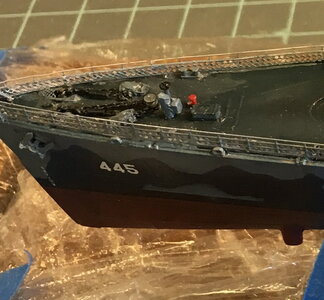
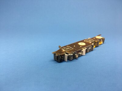
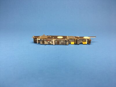
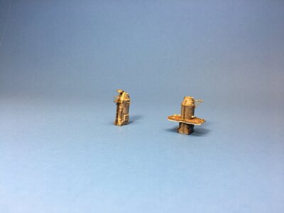
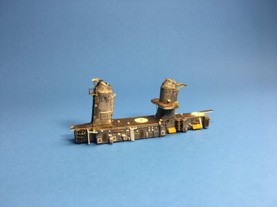
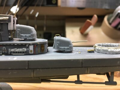
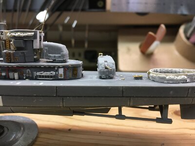
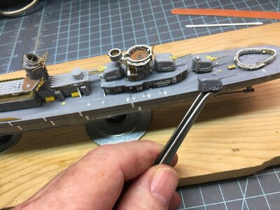
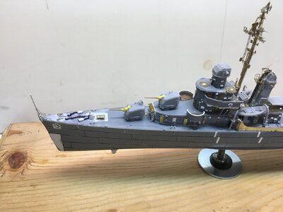
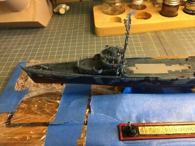
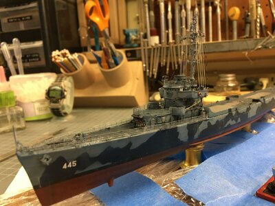
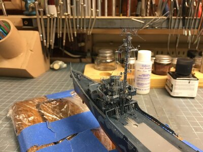
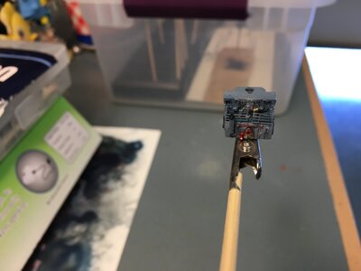
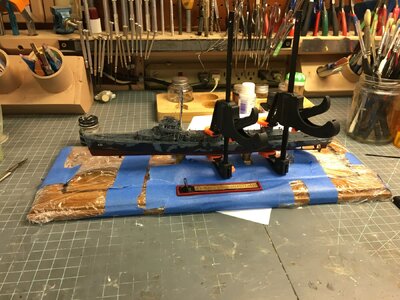
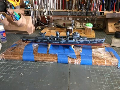
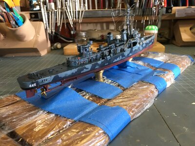
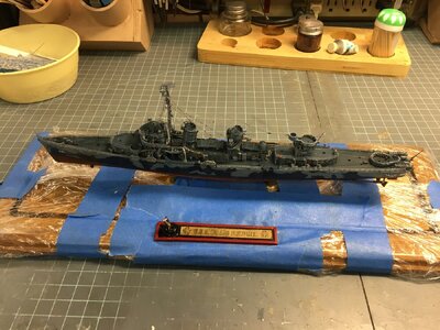
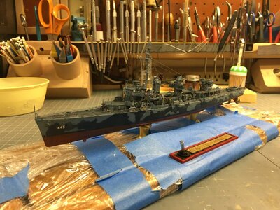
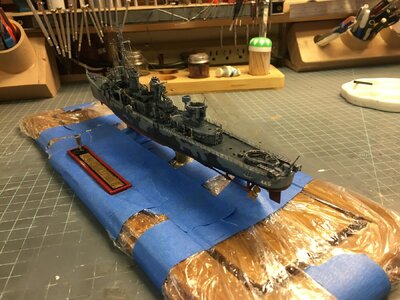
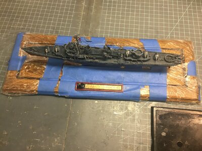
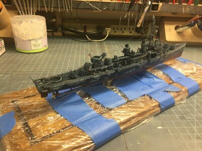
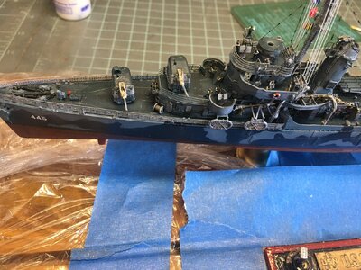
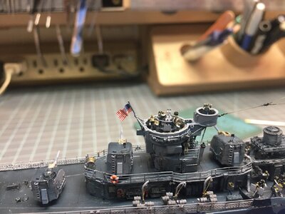
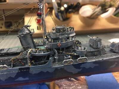
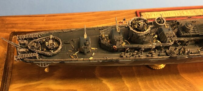
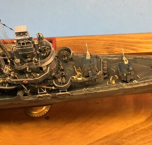
USS Fletcher DD-445, 1942 - Tamiya plastic kit of the USS Fletcher in 1/350 scale [COMPLETED BUILD]

Joined
May 8, 2021
Messages
26
Points
48

Part 1
This is perhaps unorthodox but I have completed the model and now I am writing about it. I purchased the kit to get me back into building ship models and as a precursor for building the 1/350 Mini Art Enterprise CVN-65. Normally I build 1/48 scale airplanes. At any rate I bought the ship on impulse when I saw it at deep discount on Amazon. I started researching on the internet but I eventually bought the following as references:
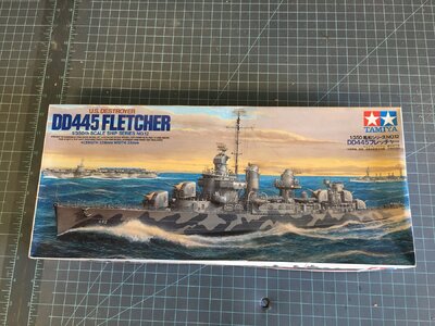

Unboxing (1).JPG

Warship Pictorial 42, Round Bridge Fletchers, Rick E Davis

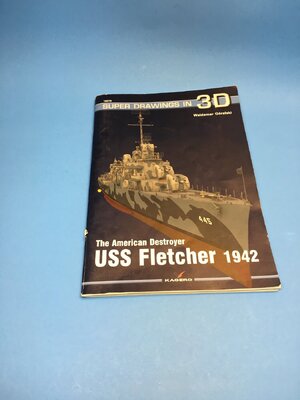
Kagero Super Drawings in 3D the American Destroyer USS Fletcher 1942, Waldemar Goralski

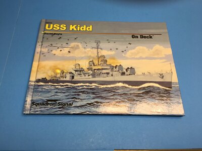
Squadron Signal On Deck USS Kidd, David Doyle

Squadron Signal Fletcher DD’s in Action, Warship Number 8, Jerry Scutts

Shipcraft Number 8, Fletcher Class Destroyers, Lester Abbey

The first 3 became my primary sources. But there is a wealth of information on line for free also. I found these to be helpful:

http://www.ussfletcher.org/

https://destroyerhistory.org/fletcherclass/ussfletcher/

http://www.navsource.org/archives/05/445.htm

https://www.shipcamouflage.com/index.htm
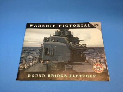


Unboxing (9).JPG


Unboxing (10).JPG

Unboxing (11).JPG
In addition to the kit I also got the following upgrade sets:

Eduard 1/350 Photoetch set for the Tamiya USS Fletcher 53003

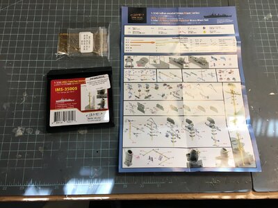
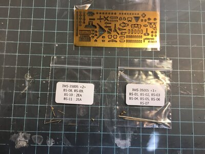
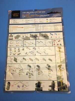
Infini Models Brass Mast set for the Tamiya USS Fletcher IMS 35005

Black Cat Models Round Bridge Fletcher 1943 Detail Set for Tamiya Kit CK350001

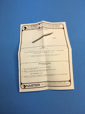
Master Models 5 inch 38 SM-350-017 (20 Brass Barrels)
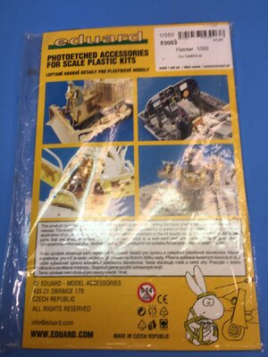

Unboxing (4).JPGUnboxing (4a).JPGUnboxing (4b).JPGUnboxing (4c).JPGUnboxing (6).JPG

In my stash of photoetch I have various railings, doors, hatches, portholes, ladders, gratings and structural components.

After seeing the quality of the Black Cat set I got several of their 1/350 stand-alone sets including figures, bitts, fairleads, anchors, lockers, life rings, hand wheels on pipe sections and draped firehoses. I also obtained a set of twin 40mm guns and a set of 20 mm guns. Most of these parts are also compatible with my Enterprise kit also.

The kit comes in a sturdy top opening box with typical excellent Tamiya artwork on the sides and top. Inside are four sprues of gray plastic parts, (two are identical) and a separate full hull. The instructions cover assembly in 5 steps. There is a gray scale drawing for painting the camouflage pattern. A small decal sheet with hull numbers 445 – 448 and some national ensigns. A bag of polycaps is also included. There are some generic instruction inserts and a set of black and white peel off stickers for the nameplate. Looking over the sprues there is an unused piece which is not mentioned in the instructions but which was handy in modelling the aft 40 mm gun tub. Even though there are 4 sets of hull numbers there are no extra nameplate stickers.
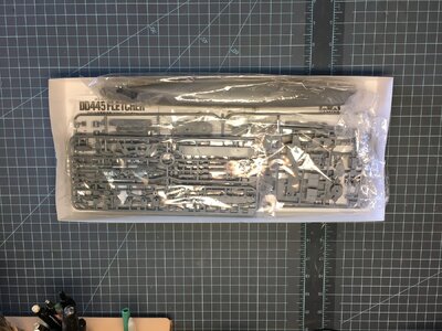
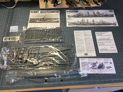
Unboxing (2).JPG


Unboxing (3).JPG


My goal was to display the ship on brass plinths on a dedicated display base with a Plexiglas cover. It would have modifications to the hull to represent all plating and full hawse pipes. The sonar and depth finder housings would be added. The ship would appear to be underway and firing on a low flying target on the port beam. My research indicated that prior to leaving for the Solomon Islands, a second twin 40 mm mount and director were added to the fantail. In addition at some point another single 20 mm gun was installed on the deck above the pilothouse. These modifications would also be added to the model.

The Infini mast set will produce a delicate and highly detailed replica of the Fletcher’s mast. There are parts to replace the kit items for aft funnel and a battle ensign staff on the funnel. This can be modified to be used on the gun tub on the aft deckhouse where it was located on Fletcher. Eduard’s set for the ship has two frets a large one and a small one. There is plenty of railing and netting to do the full ship. There are doors and hatches, an antenna for the SC – 4 “bedspring” radar atop the mast as well as a nice antenna for the Mk - 37 director. There are thinned wave breaks and midships 20 mm gun tubs. There is a plethora of details to upgrade the model.

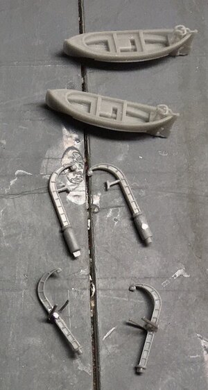
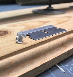
The Black Cat kit has the tiniest jewel like parts to replace all the weapons, searchlights, bridge details, whaleboats and the Mk – 37 director. These 3d printed parts have breathtakingly delicate detail. There are even auxiliary gun sights on the five inch mounts. Great care must be taken when working with these items as they are EXTREMELY FRAGILE.

A bit later in the build it occurred to me that I could open the pilot house doors and light the pilot house. I purchased some LED lighting kits from Evan Designs.
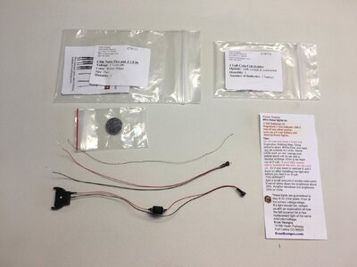

Unboxing (8).JPG

This covers the first installment. As I figure this site out I will be adding more. In the next I will cover the hull mods and the display base.
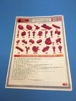
Unboxing (5).JPG

Unboxing (7).JPG
 
Last edited:
Part 2
It occurred to me that before I even glued two parts together that in order for the model to be mounted on a display I would have to arrive at some way of securing it to a base. The kit comes with the usual parts for a display stand, but I wanted something a little better, a nice stained and varnished base with a dust cover. The first hurdle was finding a suitable piece of wood. It needed to extend past the ship on all sides and be deep enough for a groove to let a clear acrylic cover fit into. And later handle the electrical connections.


Layout for Display Base (2).JPG

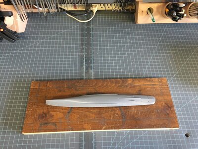
I keep most of the scrap pieces from other projects in a large box in my attic. I found an oddball piece of finished pine that looked as if it would work and I set the hull in position and laid out some lines. First the maximum rectangle I could cut out of the scrap. Next I established a centerline and working outward, one inch from the fore and aft dimensions and around two inches from the beam’s widest point. This is where the groove for the cover would be cut. The piece was cut on my table saw.

Layout for Display Base (3).JPG

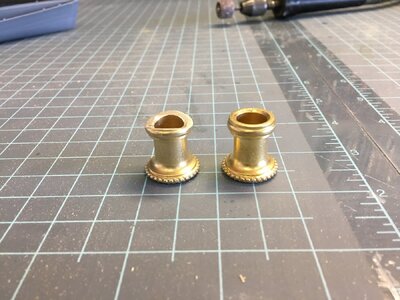
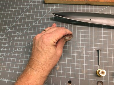
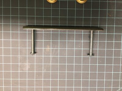
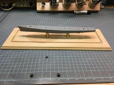
On the bottom of the hull there were some mold marks and I used these to determine where I would drill the holes for the screws. I have seen how others epoxy nuts over a hole drilled in the hull but the Fletcher is rounded on the bottom not flat. I got some 1/8 X 1” flat bar stock from my metal scrap bin, (yes a scrap bin for that too), and measured the points on the hull. I cut the bar accordingly and drilled holes and threaded them for 10/24 screws that came with the brass plinths. The pedestals were also flat where they would contact the hull. I carefully ground the mating surface so that they would also fit correctly. Doing this made the pedestals “handed” so I made some marks to show which was forward and aft and arrows to show orientation.

Making the Display Base (1).JPG


Making the Display Base (7).JPG


Making the Display Base (9).JPG


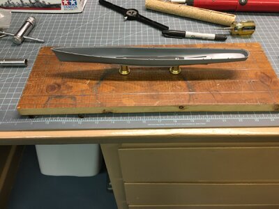
I took the bar to the grinder and shaped it to rest in the bottom of the hull. Once I had a good fit it was easy to drill matching holes in the bottom of the hull. I also drilled the base and recessed the bottom to accommodate the nuts so it would sit flat. To ensure that the assembly would stay solid I ran both the screws tightly into the bar and brazed them in place. I put JB Weld two part epoxy into the hull, inserted the bar, then placed the plinths and snugged everything to the base, ensuring the model was perpendicular. More two part epoxy went around the bar. I left everything to cure overnight.


Making the Display Base (4a).JPG


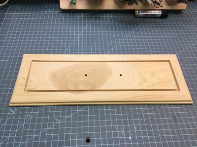
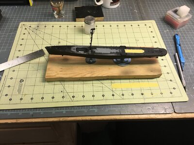
The base was routed out for the cover with my Dremel Tool. The edges received a decorative “ogee” on my router table. I sanded it with progressively finer grits of sand paper until it was clear and smooth. I glued some 1/16 cork sheet to the bottom so the base wouldn’t scratch any furniture. I stained it with some walnut and then used a satin varnish in several coats, sanding between coats until a nice smooth finish was achieved.


Making the Display Base (10).JPG

The deck is just snapped into place here. How about that Tamiya fit. Every fit issue I had with this model was self induced. No mods have been done to the hull or the deck.

Making the Display Base (11).JPG

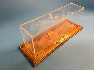
The grooves were measured and I ordered cut pieces of 1/8 inch acrylic Plexiglas to make up the cover. I ordered these pieces from Tap Plastic. https://www.tapplastics.com. They offer the cut pieces with sanded and polished edges. It is fairly expensive but I haven’t been able to cut the stuff as precisely. With the parts in hand it is only a matter of gluing them together. That said gluing is kind of an art and great care must be taken not to mar the plastic. If you do make a mistake it can be cleaned up with polishing pads, patience and a touch of scotch. Don’t ask me how I know this. The cover fit quite well.

Later in a horrendous disaster I dropped that cover and it broke sending a huge shard flying which went and sheared off my mast. This happened after the model was painted. I would have thrown the whole mess in the trash but I had too many hours and too much money invested in the project. I replaced the cover and painstakingly repaired the mast to the best of my ability. When we get to the finished pictures you can be the judges of whether or not it was worth it.

Below is the almost finished base and cover before the accident and switch replacement.


Making the Display Base (21).JPG


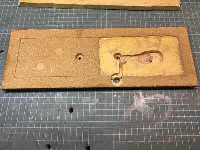
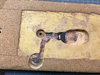
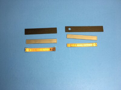
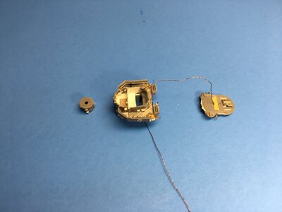
At first I hadn’t considered adding any lights to the model, but I started to mull it over and decided it could be done. Then I ordered the light kit and once it arrived I came up with a likely plan of attack. I had to grind a channel on the bottom of the base it is not pretty but It does work plus you can’t see it unless you look at the bottom. I needed to place the switch where it could be accessed. I decided to incorporate it into the name plate. I found a nice piece of textured plastic sheet in, where else but my plastic scrap bin and cut it to size. I drilled a hole to accommodate the switch. The switch, battery holder and wiring were hot glued to the channels in the base.

Making the Display Base (15).JPG


Making the Display Base (17).JPG

Drilling the hull was the most daunting part as I had to drill through the metal bar at the forward screw so the wiring could pass through the pedestal. Also all the hull mods were done and the deck was firmly glued in place. I had to work through a hole that I cut in the deck under the forward deck house. During the drilling I broke a bit and it went to the back of the ship somewhere. I couldn’t shake it out so I gave it no more thought. Later when I was prepping for paint I found a hole in the aft hull right along the keel on the starboard side. Evidently the hot bit melted through the plastic. I filled it with sprue goo and then a layer of Deluxe Materials Plastic Putty to reduce the sanding needed to fair in the repair.

When I was assembling the model and I came to the point of soldering the wiring and fixing the pilot house in place I tested the light one last time and it worked fine. After it was all glued up I did it again and it would not light. After some serious “navy” words and troubleshooting I found out the switch was bad. Once it was replaced with a switch from another kit it worked exactly 3 times and failed again. I bought 3 of these light kits and rather than use another switch since they failed so easily, I looked through my electrical scrap box, (no surprise there), and found a small switch that wasn’t so cheaply made. I had to modify the nameplate to handle the it. The push-on-push off switch looked better but you have to go with what works.


Making the Display Base (13).JPG

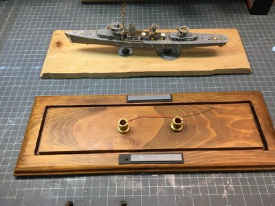
Part of the Eduard set included a brass etched nameplate designed to fit into Tamiya plastic part. I used this and added a plastic frame around the whole thing which I painted red. I was going to use both nameplates but decided to just go with the one in the end.

Here is a preview of the ship while I was working up the base. This is all dry fit together. I didn't care for the two nameplates when I mocked it up so I discarded one.

Making the Display Base (19).JPG

In part three I will describe how I detailed and modified the model.
 
Last edited:
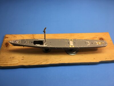
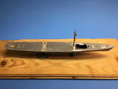
Part 3
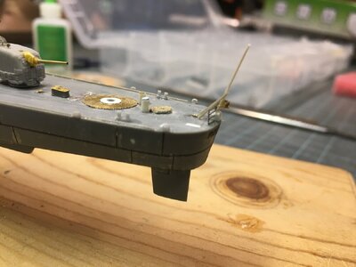
The first thing I changed was the port and starboard hawse pipes. On the model they are molded shut and the anchor chains are molded to the deck. So I used a micro chisel and removed all traces of the chains. Out came my trusty hand piece and I proceeded to drill out the openings on the deck and the sides of the hull. I had some Black Cat Destroyer anchors and I tried inserting one through the hull and up to the deck. It wouldn’t go. Obviously I just needed to run the drill from one hole to the other to make it work. This allowed the anchor shank to pass through correctly but it left a visible blank area form at both openings.

I had no problem with gluing the deck to the hull at this point so I went ahead and did so. I got a section of Plastruct ABS 1/8 inch tubing to pass through the openings but I had to drill the holes out larger. This pretty much did in the molded flanges both on the hull and the deck. I glued the tubing in place on both ends leaving some hanging out. When the glue dried, I shaved off the tube flush. I also shaved off all the remaining flanges, the chain locker covers, the anchor winch and sanded everything smooth. Using progressively larger bits I drilled out the tube till the anchor shank passed through.

I scanned the 1/350 drawings of the ship from Goralski’s book. I used these to create a pattern for my Cameo cutting machine in Corel Draw. There is a reinforcing plate around the hull openings and another reinforcing plate on the bow, so these were included in the patterns for the chain locker covers and the hawse pipe openings. I built up the covers and the hawse pipes out of several layers of .005 plastic sheet. All these items were cut out, glued together and with the exception of the chain locker covers attached to the model. I found photoetched rings that matched the hull opening so I glued these on also.

The model’s chain locker layout disagreed with the Goralski plans so I used these to mark the chain locker and winch locations. I made the winch from plastic discs punched out of various thickness of plastic sheet. A piece of wire runs through them all and into a corresponding hole in the deck. The link is to a pretty decent photo of the foredeck of a DD although there are no gun mounts.

https://www.worldaffairsboard.com/filedata/fetch?id=1468090


5th Dryfit (7a).JPG

Aft Railings, Gun Tub and Depth Charges Installed (11a).JPG

Forward Railings and boat davits (3a).JPG


There is only the single anchor winch. It has an upper and lower section which operated independently of each other. The top is a capstan to put tension on rope cable, say for mooring ropes. The bottom is the wildcat which acts as a sprocket to raise and lower the chain. One anchor chain is routed from the aft end of one of the chain locker covers, (it could be on either side), and from there around the winch to the hawse pipe. The other chain exits from the forward end and straight to the other hawse pipe. Both chains are secured with pelican hooks to pad eyes between the chain lockers.

If both anchors needed to be used at the same time one would be raised at a time. When the first is up and secured, the chain is physically moved from the wildcat and the other is set in its place. There are locations where a hoist could be set on deck and a block and tackle rigged to move the chains. There are covers for the open ends of the chain locker covers. The anchors weigh 2 tons each and one has 120 fathoms of chain and the other 90. 720 and 540 feet respectively I got this information from the virtual tour of the USS Sullivans. I guessed that was how it worked but I wanted confirmation.

www.usskidd.com
I am a retired Senior Chief but an Airedale so I didn’t get any training in this area.


I’m pretty ham fisted so I managed to break off a good many of the molded fairleads and bitts while I did the above work. Which is why I purchased the Black Cat sets. Since the details no longer matched, I replaced them all. (In the previous part about the base there is a photo of the model with deck snapped into place. The forward stbd fairlead is already broken off.)

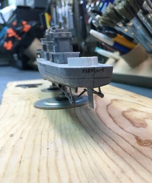
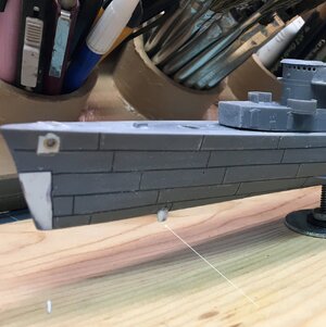
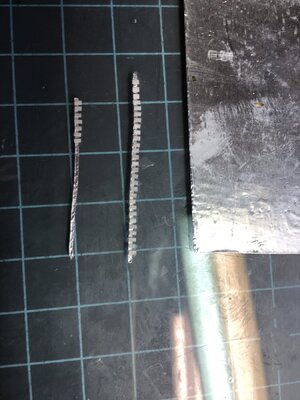
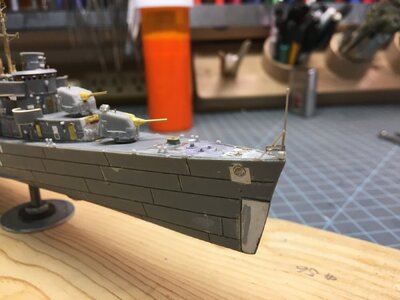
I wanted to represent weld lines for all the hull plating I tried using stretched sprue glued into position over penciled lines. I just couldn’t make it look right. I ended up sanding it all smooth. I got an email from a company that I brought dry transfers from. (Archers, sadly now out of business.) They had several resin products on waterslide decal film, welds for armor, rivets for aircraft and resin lines for those older models with only raised detail. I ordered up some sheets to try them out. They had a sheet with various thicknesses and the smallest was promising.

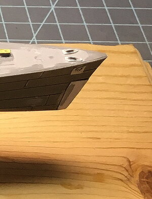
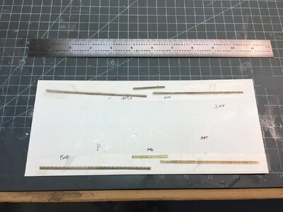
I sprayed some Testor’s Glosscoat on the hull and gave them a try. I found they were easy to position exactly when applied into a puddle of Micro Set. Once dry you apply some Micro Sol and when dry the film has almost disappeared. I did all the longitudinal lines first on one side and then the other matching the lines much as you would match planks on a wood model. After that the vertical lines were added. I measured each with a divider and then cut it with razor knife. I noticed that the drawings showed reinforcing plates at the vertical joins of the top two rows of plates amidships only. I added these with lengths of .005 Evergreen strip instead of the decals. It looks a bit heavy handed, but after a second gloss coat then primer and color coat came out nicely. While I was working on this I noticed the “Archers Fine Transfers” logo on the sheet had all the elements to spell out Fletcher so I applied them also.

US Navy ships often have the name cut from plate and welded to the stern then painted in black. During the war ships names were painted out with the hull color, and hull numbers were unshadowed and reduced in size.


1st Dryfit (3).JPG


In this photo showing the hull plating note all of the fairleads and bitts have been removed


1st Dryfit (8a).JPG
The stern note the prop shafts are just dry fitted

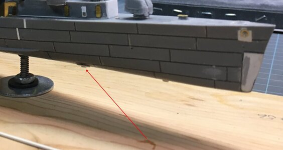
The Sonar and the Depth Finder Domes are visible in photos on pages 68 and 69 of the Warship Pictorial Book. I simply sanded small pieces of scrap plastic to shape and glued them into position. I also drilled holes for bilge pump outlets and intakes


1st Dryfit (3a).JPG

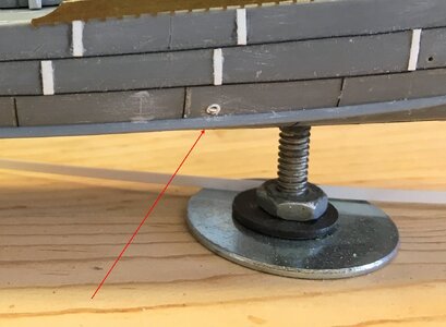
Arrow points to Sonar Dome. Note the reinforcing plates on the bow and around the hawse pipe.

2nd Dryfit 5 Inch Mounts and Fwd Torpedo Tubes (7a).JPG

Arrow points to depth finder radome


Midships Deckhouse (10a).JPG

Arrow points to intake

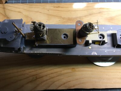
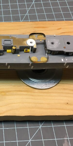
At this time I also added the majority of Eduard photoetch to the deck as well as generic hatches where Eduard didn’t cover something. Some locating holes were filled with strip where I would be substituting the Black Cat parts for the kits. Finally scuppers visible in references were made from lengths of sprue and glued to the edge of the deck. You want to leave space for railings if you do this. I removed a locating strip for the break water on both sides of the deck. Some of the nonskid walkways on the kit’s deck didn’t match with photos or the drawing. I corrected this with strips of Bare Metal Foil. I used a large punch and die set (3/16 to ½ inch) to create circular gratings for gun positions. I added the rudder to the hull but I was afraid that I would damage the prop shafts if I glued them on at this time. I also thought it would be hard to paint if they were glued on. Right before I was going to paint I did break them and had to glue them on in order to fair in the repairs. Turns out they were not hard to paint.

Final Dryfit (1).JPG


Final Dryfit (2).JPG

In both the above photos I got a mite over enthusiastic with cutting the opening in the foredeck to run the pilot house wiring. you can see the white plastic strip where I had to put some material back.


Masking and Painting (43).JPG
This photo shows the deck work under a coat of primer and paint.

In The next installment I will cover assembling the deckhouses.
 
Last edited:
The last plastic model I did was 75 years ago! You've whetted my appetite to try again, but such a small scale would be impossible for me even with the surgical glasses that I use with my wooden models.. The plastic models have apparently come a long way since I was a kid. Amazing! Beautiful work and of a size that the wife would not be going ballistic with my ships taking over the house! Again -- Great work and skill!
 
I converted the square bridge Fletcher to the USS Kidd in the late anti-Kamikaze configuration. Had to do a bit scratch building because all the beautiful 3D upgrades weren't available at that time.
You have done an outstanding job of documenting your project. Thanks for sharing. Will be watching for future posts.
 
The last plastic model I did was 75 years ago! You've whetted my appetite to try again, but such a small scale would be impossible for me even with the surgical glasses that I use with my wooden models.. The plastic models have apparently come a long way since I was a kid. Amazing! Beautiful work and of a size that the wife would not be going ballistic with my ships taking over the house! Again -- Great work and skill!
Thanks Paul I'm going to be trying to make space if ever I complete that Enterprise myself
I converted the square bridge Fletcher to the USS Kidd in the late anti-Kamikaze configuration. Had to do a bit scratch building because all the beautiful 3D upgrades weren't available at that time.
You have done an outstanding job of documenting your project. Thanks for sharing. Will be watching for future posts.
Thanks for your kind remarks
 
Part 4

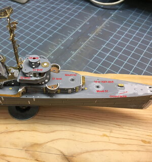
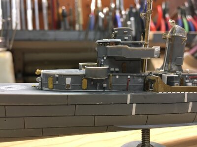
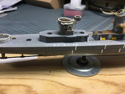
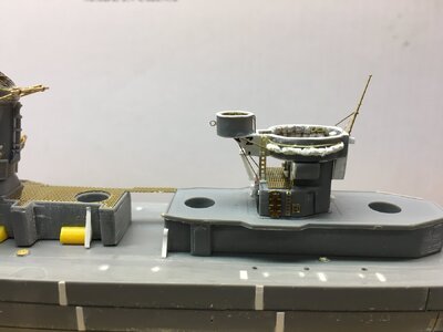
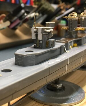
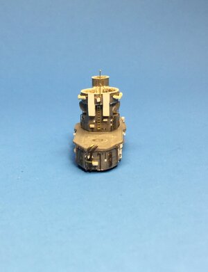
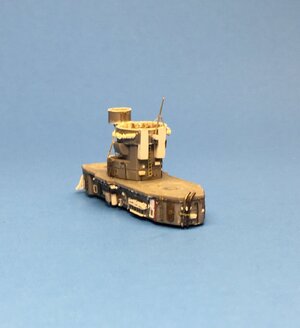
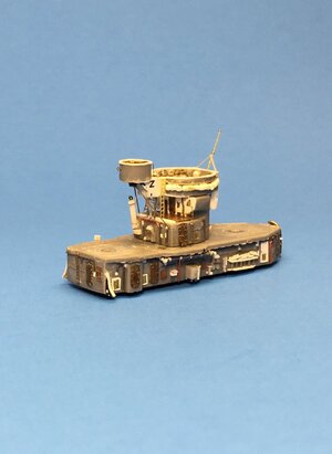
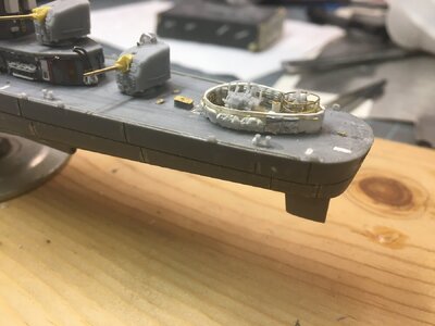
On the main deck forward is all the ground tackle, Mount 51, (forward most 5 inch gun) and the forward superstructure. The forward deckhouse is the command and control hub of the ship. The Mk37 Director is the main fire control element for the five 5 inch gun mounts. It sits at the top on the 04 level. The mount or pedestal is on the 03 level above the pilot house and the bridge which are on the 02 level. One single 20 mm cannon is on the 03 level forward. (This probably is an in theater modification, I did not find anything written on it but I found a couple of photos). The 01 level supports mount 52 and 2 more single 20 mm cannons in port and starboard tubs.

Forward Deckhouse (1a).JPG

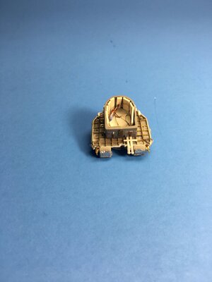
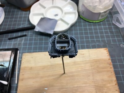
I began by thinning the front piece of the pilot house from the backside and then drilling out the portholes. I used generic photoetch portholes and plastic strip to add more detail. I also thinned the side pieces and opened both bridge doors. On the interior I used the generic portholes with the armored covers. I managed to break the stbd half of the pilot house aft of the door and had to fix the bulkhead with some plastic sheet. I assembled the 3 bulkheads of the pilot house and used them as a template to cut out a deck. I glued plastic strip around the inside to support the deck. I also made a rear bulkhead to close off the bridge. For some reason I got pretty carried away detailing the interior and this is why I decided to light the space. Goralski’s book has a couple of nice views of the bridge interior and using various pieces of plastic strip and lead wire I made most of it. There is a helm, throttle, compass and binnacle. Even the Captain’s chair and a radar scope/plot table were added. These items were kept separate until the painting was done. I glued a section of grating on the deck.

Forward Deckhouse (6).JPG


Forward Deckhouse (7).JPG

Forward Deckhouse Final (5).JPG


The bridge wing deck was added and the underside was detailed with L’Arsenal structural photoetch elements and lead wire. Port and starboard running lights were scratch built and added to the underside. Two large insulated conduits exit from the back for radio antenna leads and these were also scratch built and added. The splinter shields were added to the bridge wing deck. I made some fighting lights for each side of the bridge wings (I’m not sure but I think these were some sort of quick friendly ID). I did not use Eduard’s watertight doors as Tom’s Modelworks are more detailed and they can be open or closed and include frames.

Forward Deckhouse Final (9).JPG

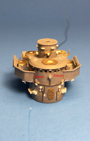
One thing I’ve noticed about most plastic model ship kits is that they rarely include a representation of all the wiring, boxes, light fixtures and the like that are affixed to every available space on a warships exterior. Almost every exterior bulkhead should have handrails on a destroyer and every position has a sound powered phone box. So I attempted to up detail each assembly to reflect all of this. Of particular note are the two Klaxon horns on the front of the pilot house. I made these from scratch with stretched sprue.

Forward Deckhouse Final (4a).JPG

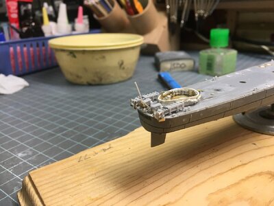
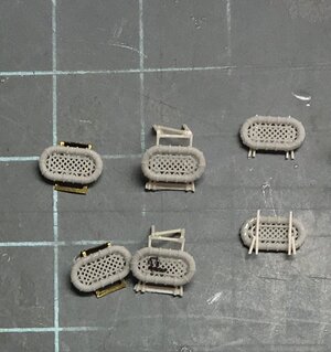
To use the Black Cat 5 inch mounts I had to fill the holes in the deck. I used the parts intended to trap the polycaps in place. I cut these off so they would be flush with the deck and glued them in place without the polycaps. The Black Cat Guns include the mount flanges. The main deck portion of the forward deckhouse was assembled and I managed to over sand many of the mating surfaces and had to correct with strip glued and sanded flush. (I do this a lot.) Eduard provided some nice parts to detail the 20 mm gun tub decks and replace the breakwater. One simplification of the kit is that part A-17, the aft bulkhead/ 01 level deck is made so the aft bulkhead is not recessed. The deck should provide an overhang. The aft bulkhead has to be removed and sanded flush and a new aft bulkhead made from strip and glued forward about 4 mm or where the angle of the breakwater starts.

Forward Deckhouse (2a).JPG

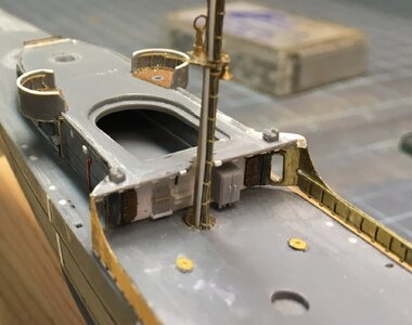
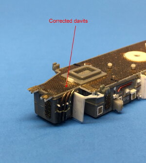
The photoetch for the breakwaters and the gun tubs does not include any structural elements for the tub splinter shields or the inside of the breakwaters. I used some single bar railing, (not part of the Eduard set), to detail these areas. At the kit’s forward davit locations there is a solid triangular tab that is part of A-17. This should be open so it was cut off on both sides and stretched sprue was glued to each davit, part C-21. There is another triangular piece aft of this that supports the breakwater it also has a chock to hold the keel of the motor whaleboat, (you don’t want to remove this). There are three struts on each side to support the bridge wings. I tried making them out of stretched sprue and gluing them to the lower level. But they did not stand up too well. I cut them off and used photoetch fret material to make 2 sets but left them off till final assembly.

Forward Deckhouse (12).JPG

There are vent intakes and exhausts on most of the main deck superstructure some have flip up covers and some don’t. These are not represented in the kit or any of the accessories. I made these from plastic cut on my Cameo machine and photoetched screen. The forward end of the main deck superstructure is a fire station. There are two flaked hoses, a hose reel, some applicator extensions and two fire plugs. The draped hoses that I got from Black Cat have marine strainers attached but on Fletcher they were usually located somewhere close but not at the fire station. Above the station there is a floater net basket. I found a photo etch sheet that has the buoy strings. Being photoetch they are kind of 2 dimensional so I used some thick superglue to build them up. The basket and a fold up string of buoys were ca glued to the front. On the aft bulkhead I added welding tanks in a rack and a generic locker. I believe a damage control locker was located there.

Forward Deckhouse Final (14).JPG

Forward Deckhouse Final (15).JPG

Note on this aft view the flag bags and tarpaulins

Forward Deckhouse Final (16).JPG

Parts are dry fitted

Forward Deckhouse Final (2).JPG


In Part 5 I will cover the midships deckhouse.
 
Part 4

On the main deck forward is all the ground tackle, Mount 51, (forward most 5 inch gun) and the forward superstructure. The forward deckhouse is the command and control hub of the ship. The Mk37 Director is the main fire control element for the five 5 inch gun mounts. It sits at the top on the 04 level. The mount or pedestal is on the 03 level above the pilot house and the bridge which are on the 02 level. One single 20 mm cannon is on the 03 level forward. (This probably is an in theater modification, I did not find anything written on it but I found a couple of photos). The 01 level supports mount 52 and 2 more single 20 mm cannons in port and starboard tubs.

View attachment 452194

I began by thinning the front piece of the pilot house from the backside and then drilling out the portholes. I used generic photoetch portholes and plastic strip to add more detail. I also thinned the side pieces and opened both bridge doors. On the interior I used the generic portholes with the armored covers. I managed to break the stbd half of the pilot house aft of the door and had to fix the bulkhead with some plastic sheet. I assembled the 3 bulkheads of the pilot house and used them as a template to cut out a deck. I glued plastic strip around the inside to support the deck. I also made a rear bulkhead to close off the bridge. For some reason I got pretty carried away detailing the interior and this is why I decided to light the space. Goralski’s book has a couple of nice views of the bridge interior and using various pieces of plastic strip and lead wire I made most of it. There is a helm, throttle, compass and binnacle. Even the Captain’s chair and a radar scope/plot table were added. These items were kept separate until the painting was done. I glued a section of grating on the deck.

View attachment 452195


View attachment 452196

View attachment 452197


The bridge wing deck was added and the underside was detailed with L’Arsenal structural photoetch elements and lead wire. Port and starboard running lights were scratch built and added to the underside. Two large insulated conduits exit from the back for radio antenna leads and these were also scratch built and added. The splinter shields were added to the bridge wing deck. I made some fighting lights for each side of the bridge wings (I’m not sure but I think these were some sort of quick friendly ID). I did not use Eduard’s watertight doors as Tom’s Modelworks are more detailed and they can be open or closed and include frames.

View attachment 452199

One thing I’ve noticed about most plastic model ship kits is that they rarely include a representation of all the wiring, boxes, light fixtures and the like that are affixed to every available space on a warships exterior. Almost every exterior bulkhead should have handrails on a destroyer and every position has a sound powered phone box. So I attempted to up detail each assembly to reflect all of this. Of particular note are the two Klaxon horns on the front of the pilot house. I made these from scratch with stretched sprue.

View attachment 452207

To use the Black Cat 5 inch mounts I had to fill the holes in the deck. I used the parts intended to trap the polycaps in place. I cut these off so they would be flush with the deck and glued them in place without the polycaps. The Black Cat Guns include the mount flanges. The main deck portion of the forward deckhouse was assembled and I managed to over sand many of the mating surfaces and had to correct with strip glued and sanded flush. (I do this a lot.) Eduard provided some nice parts to detail the 20 mm gun tub decks and replace the breakwater. One simplification of the kit is that part A-17, the aft bulkhead/ 01 level deck is made so the aft bulkhead is not recessed. The deck should provide an overhang. The aft bulkhead has to be removed and sanded flush and a new aft bulkhead made from strip and glued forward about 4 mm or where the angle of the breakwater starts.

View attachment 452215

The photoetch for the breakwaters and the gun tubs does not include any structural elements for the tub splinter shields or the inside of the breakwaters. I used some single bar railing, (not part of the Eduard set), to detail these areas. At the kit’s forward davit locations there is a solid triangular tab that is part of A-17. This should be open so it was cut off on both sides and stretched sprue was glued to each davit, part C-21. There is another triangular piece aft of this that supports the breakwater it also has a chock to hold the keel of the motor whaleboat, (you don’t want to remove this). There are three struts on each side to support the bridge wings. I tried making them out of stretched sprue and gluing them to the lower level. But they did not stand up too well. I cut them off and used photoetch fret material to make 2 sets but left them off till final assembly.

View attachment 452209

There are vent intakes and exhausts on most of the main deck superstructure some have flip up covers and some don’t. These are not represented in the kit or any of the accessories. I made these from plastic cut on my Cameo machine and photoetched screen. The forward end of the main deck superstructure is a fire station. There are two flaked hoses, a hose reel, some applicator extensions and two fire plugs. The draped hoses that I got from Black Cat have marine strainers attached but on Fletcher they were usually located somewhere close but not at the fire station. Above the station there is a floater net basket. I found a photo etch sheet that has the buoy strings. Being photoetch they are kind of 2 dimensional so I used some thick superglue to build them up. The basket and a fold up string of buoys were ca glued to the front. On the aft bulkhead I added welding tanks in a rack and a generic locker. I believe a damage control locker was located there.

View attachment 452210

View attachment 452211

Note on this aft view the flag bags and tarpaulins

View attachment 452212

Parts are dry fitted

View attachment 452214


In Part 5 I will cover the midships deckhouse.
I like the additional detail you are adding to the kit, nice work
 
Part 5

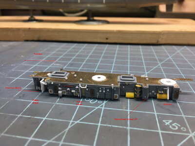
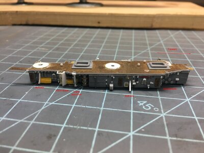
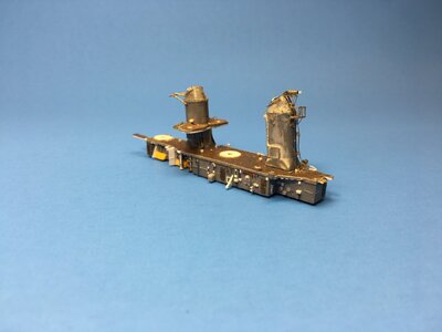
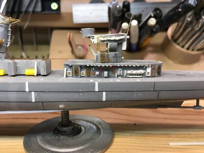
The midships deckhouse held the uptakes for the two funnels, sickbay, the supply office and the Midship Repair locker. It assembles out of four parts, A-23 and A-24 are the port and starboard sides, (they each contain a portion of the forward bulkhead,) A-3 is the aft bulkhead and B-13 is the deck. I found that the two sides wanted to bow in so I glued 2 sections of sprue to help hold them in position. If you use the Eduard set it has a perforated deck for this portion of the superstructure. This is partially correct as any overhanging portions of the deck were perforated but the inner area was solid. I just used this part as supplied and glued it in place early on.

Midships Deckhouse (3).JPG

Midships Deckhouse (1).JPG

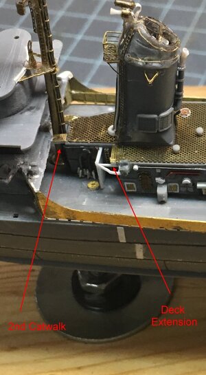
There are catwalks that connect the forward and aft deckhouse. The kit portrays this but I removed them from the aft deckhouse and from B-13. I used plastic strip to add some support to these metal catwalks. All the overhanging decks were detailed with strip on the underside to portray the support structure. I used photoetched grating to add a second catwalk forward and an overhang extension where the fwd funnel’s ladder meets the deck. 3 mushroom vents were added to the deck area

Midships Deckhouse (17a).JPG

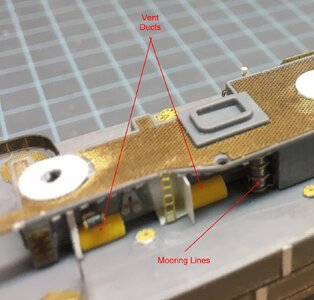
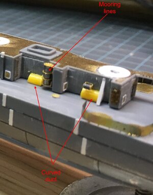
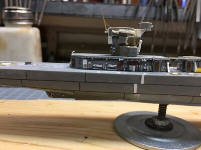
There are four vent trunks on the aft end of the deckhouse, the kit has protruding boxes but these should be rounded over not rectangles. I grabbed some sprue that I could cut these out of, (yellow,) I removed the kit features and glued the sprue to replace them, be aware that when you cut these off there will be gaping holes. There were too many doors represented on both sides and in the wrong places so they all were removed and replaced. The port and stbd ladders on this structure were each protected by a wave break and these were built up but not completely installed yet. There is a stanchion which supports the torpedo handling crane and three buttresses which had to be fabricated. Eduard provides buttresses for the aft deckhouse but none on the midships deckhouse.

Midships Deckhouse (5a).JPG

Midships Deckhouse (8a).JPG


Midships Deckhouse (21a).JPG

Midships Deckhouse (22a).JPG

The kit and the Black Cat torpedo tubes are not the same size. When I dry fitted them I realized that the mounts would have to be moved. The forward tubes would hit the forward funnel and so did the aft tubes. I punched out to discs of .010 plastic and located them so that everything was in the right place and the tubes could be turned without running into anything. Once the positions were finalized I glued the discs down and when dry, drilled new locating holes.

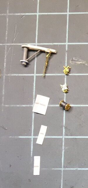
There were two vertical triple rope reels that I made up with generic photoetch and rod. I believe this is how the mooring lines were stowed. I wrapped all the various cable reels with wire to simulate what was on each. At the port forward end of the structure 3 Hoist davits were stowed. These would be the same as the hoists for the k-gun depth charges included in the kit. I had nothing that would fill in any of my stashes so I made 6 out of wire and glued plastic gussets on the base. These would not hang in place on the bulkheads. I finally realized that the bases were welded in place around the deck. There were four aft near the depth charge racks and two on the bow near mount 51. I was certain there would be a couple around the anchor chain covers but I could not find anything to document this.

Midships Deckhouse Final (7b).JPG

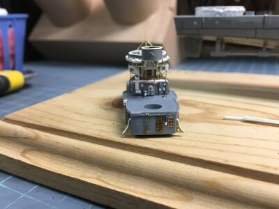
The funnels were assembled, but the splinter shields around the spotlight platform were removed. This should be railing with a canvas wind block. The forward funnel has a platform near the top but Eduard did not provide any dedicated railing for it or include directions to fold one. I added wiring and pipes on both funnels. There should be a horn and siren on top of the fwd funnel. I scratch built these. On the aft end of both funnels there is a steam pipe and I managed to break the tips of both off, one while trying to drill it out and the other through just being clumsy. To the tops of the funnels I cut out the plastic opening and worked diligently to use the Eduard detail parts. Eventually I removed them and using some of their parts and plastic strip I made my own.

I also added hand and foot rails made from generic photoetch ladders. I spent a lot of time working on these funnels, I applied the photoetch parts and did not care for the messy finish and redid them several times. I also cut 4 sections of tubing and glued them to the funnel interiors to represent internal plumbing. On the forward starboard side there is a panel with several handwheels. I used the Black Cat set for these. On the aft port side there are 4 more. All of them are protected except for one on the port side. I must have knocked this off a half dozen times. The aft funnel has some brass parts from the mast set to replace kit part A-6. It also has a flag staff that is to be placed on the aft funnel. That was the normal location on many early Fletchers but on DD-445 the flag staff was placed on the aft edge of the fwd 40 mm gun position. The National Ensign was flown here maybe there was some concern that stack gas would foul the flag.

Midships Deckhouse Final (5).JPG

Midships Deckhouse Final (4).JPG

Note the third klaxon on aft end over vent

Midships Deckhouse Final (6).JPG

Midships Deckhouse Final (7).JPG

Midships Deckhouse Final (7a).JPG

Note that handwheel has been replaced

Midships Deckhouse Final (1).JPG

Midships Deckhouse Final (3).JPG

Midships Deckhouse Final (8).JPG

Midships Deckhouse Final (9).JPG

In the next part I will cover the aft deckhouse.
 
Part 6

Aft Deckhouse

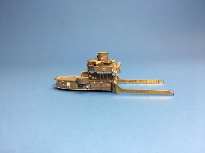
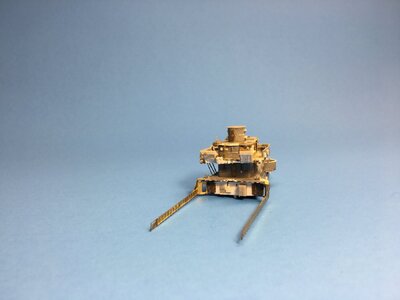
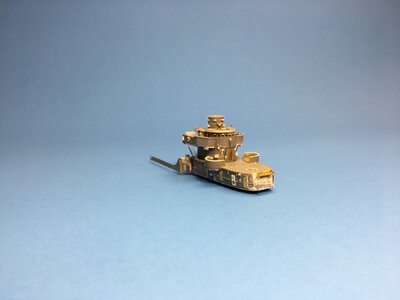
The after deckhouse was another command and control and weapons portion of the superstructure. The 02 level forward was Secondary Con. If the bridge was incapacitated then the ship could be controlled from there. In later Fletchers the upper (02 and 03 levels) of the aft superstructure were heavily modified changing the 40 mm gun tub and lowering the overall height of the superstructure. Secondary Con was moved but I don’t know where. This modification was also made to Fletcher later in WW II. The spaces enclosed with the exception of the Fan Room/Crew Shelter aft of Secondary Con and the Crew’s Head, Aft Battle Dressing Station and a passageway on the main deck all dealt with serving mounts 53 and 54. The 40 mm Gun and Director sat at the top.

The kit parts for the main deck structure and the 02 level were assembled but not glued to each other at this time. The gun tub was also treated as a subassembly. I made the following modifications, the spent shell casing trunks were extended below the gun tub to about the same level as the 02 deck. I detailed the inside of both tubs with railing like I did on the forward section. The gun tub was detailed with ready ammo racks, (I did not use the Eduard part as it did not look realistic). I made ammunition with 4 strands of stretched sprue glued together. These were then cut to the same length with my chopper. I glued these to strips of aluminum tape and a second strip was glued
over this. The strips were glued to the inside of the tub.

Gun Tubs (4).JPG

Aft Deck House (6).JPG

Aft Deck House (9).JPG

I installed the Eduard photoetch for the deck of the gun and director tubs. Around the outside circumference of the gun tub I added a grab rail using the same method as I did on the funnel. Hanging from this are rolled up tarpaulins. When the guns were not in use the tarps were pulled inside and they covered the ready ammo racks. I made the rolled tarps from Milliput Superfine White 2 part epoxy putty. They were very tiny and it was much harder than I thought it would be when I came up with the idea.

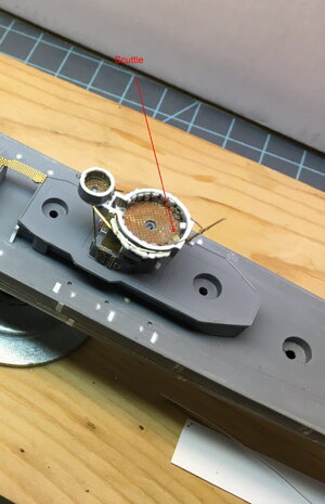
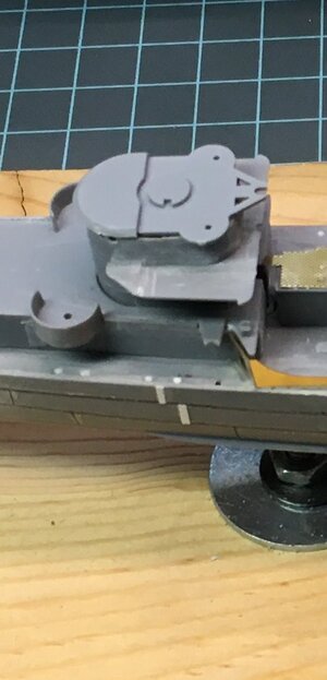
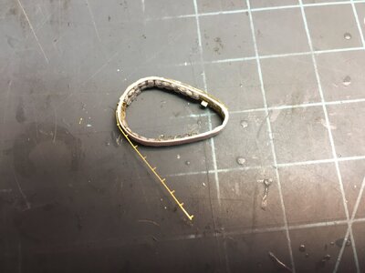
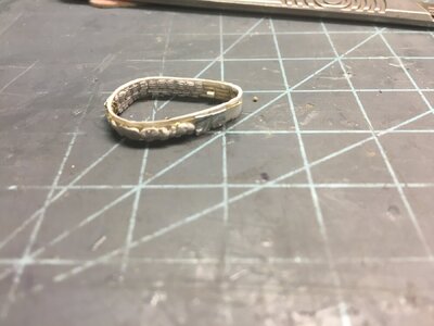
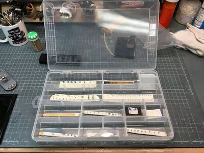
There is some sort of rectangular antenna just under the rim of the tub between the two shell ejection chutes. I made something that looked like the item and glued it in place. It is wired so it is some sort of active device. The flag staff from the Infini kit was also added. Under the tub strip was add to resemble structural frames. The Eduard kit has a set of support struts for the director tub, (parts 13 and 62), which were added, along with access ladders. Plastic sheet was shaped and glued to the bottom of the director tub mount. More sheet was cut out and placed on the top edge of the tub to form a new rim raising the height of the splinter shield. There is a ladder on the aft end of the 02 level superstructure between the chutes. It goes right up to the bottom of the tub so I assumed it was an access to the tub and glued a scuttle, small round hatch,) in the deck of the tub. Afterwards I treated the gun tub with extreme care, stowing it in a plastic storage case with all the other super fragile parts.

Aft Deck House (10a).JPG

Aft Deck House (20a).JPG

The forward face of Secondary Con was heavily detailed with strip, lead wire and screen. I used a Tom’s photoetched door. Like the other sections of the superstructure I added fire stations, fire plugs, applicators, plumbing vents, marine strainers, ventilation exhausts and intakes. One area that was difficult to portray were the spare arbor racks for the K-gun launcher. I drilled holes in 2 sections of stacked strip so the holes lined up vertically. Lengths of round sprue were glued through both sections. These were cut to length so a small portion extended below the bottom rail. The top was cut flush with the upper rail. I made one rack of 6 for the port side and two racks of three on the stbd. I heated a thin metal rod and then worked a strip of plastic along its length to form a curved chute. This was cut into equal lengths then the tips were cut at an angle. These were glued to the top rail centered over every other vertical rod. A second layer is then glued over the first centered over the remaining rods.

Aft Deck House (17).JPG

Aft Deck House (23).JPG

Aft Deckhouse (24).JPG

On the aft bulkhead of the first deck structure are more sets of davits. Escape hatches are placed on each side about in the middle of the structure. There are four refueling hoses stored under the overhang of the 01 level. Eduard provided a pair of buttresses for the forward end of the deckhouse. Each consisted of two parts I used the portion which extended perpendicular to the bulkhead, but I simply could not get the metal strip to conform correctly to its edge even after it was annealed. In the end I resorted to plastic strip. I never broke any of the buttresses on the midships deckhouse, but these metal ones had to be reattached several times. (So vulnerable and so tiny.)

Aft Deckhouse Final (6a).JPG

Aft Deckhouse Final (4a).JPG

Aft Deckhouse Final (3a).JPG

Aft Deckhouse Final (1a).JPG

That's it for this installment. Next time I'll deal with the mast.
 
Part 7
The Mast

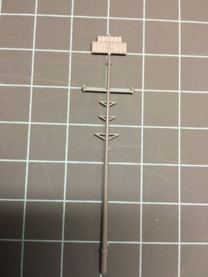
You could build this kit out of the box and have a pretty good model. You could upgrade it with Eduard or Tom’s Modelworks and make a nice little jewel. But the kit mast, even with some photoetch, just doesn’t look very realistic. I found out about the Infini mast just by Googling “Tamiya Fletcher upgrades.” Just looking at the photo of the completed mast in situ on the small box it comes in is pretty amazing.

Mast (0).JPG

https://www.infini-model.com/produc...set-for-tamiya-kit/912/category/78/display/1/

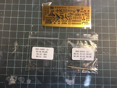
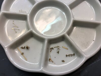
When I opened that box and pulled out the bag of microscopic brass parts and the single fret of equally small photoetch parts. I just wondered if I could pull it off.

Unboxing (4b).JPG

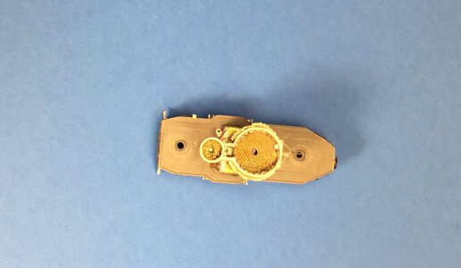
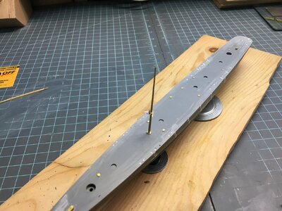
You must remove the plastic attachment point on the aft of the pilot house roof and the polycap tab from the back wall of the forward deckhouse. The infini mast fits nicely into the deck recess with no other modifications. The mast is raked aft and so the mast instructions have you fit BS-02 in place with the complete forward deckhouse assembly. It was easy to get it in the right position with the dry fitted deckhouse parts. I added the little assembly with the DF loop and the ships bell that will take the place of the tab from the pilothouse. I did not want the mast to move around after this was aligned so I made a grievous error when I tacked the mast in place with a tiny amount of thin super glue thinking I could break it loose later with some debonder. You do need the mast to hold position but I should have used white glue. Later I found that I could not get it out without damaging it.

Mast (9).JPG

Mast (3).JPG

At any rate the mast does build up nicely with the instructions being pretty clear even though they only use part numbers and pictures. I did lose a couple of items to the dead zone but I was able to fabricate replacements. I did not try to contact the company for replacements. The company website http://infini-model.com does provide contact info but I did not see any replacement part information. Some of the smallest parts had spares on the fret.

Mast (4).JPG

Mast (5).JPG

Some of the subassemblies

Mast (6).JPG
The Radar dishes are mounted as if rotating

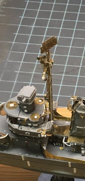
So after everything was built I checked my references and saw that there would have been a cable run and wave guides on the back of the mast and I fabricated them to the best of my ability. Now the only problem was to avoid breaking it. This I did not do. I lost track of the number of times that I broke the SC-4 Radar dish off, suffice it to say that I lived to regret my mistake. When it came time to paint the model I finally did it in when I snagged my shirtsleeve on the mast and completely broke off the top section scattering parts all over the workshop. Worse I bent the lower part of the mast. Since it was toast I was able to remove it.

Mast (10).JPG

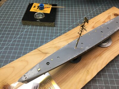
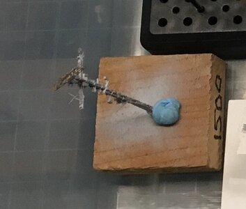
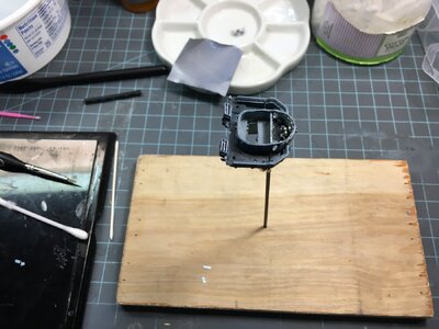
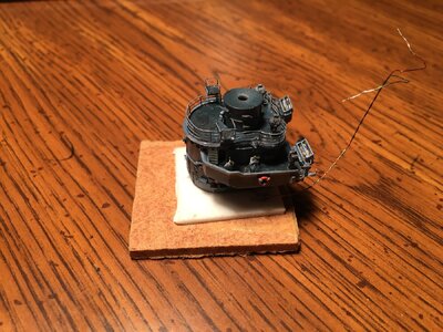
I ordered a second kit and built it up. This time I used white glue and when I had the major parts oriented correctly I removed the mast from the ship and secured it to a wood block until final assembly. Unfortunately this was not enough to keep the second mast safe. As I started putting the ship together I realized that I would not be able to add the mast after the rest of the parts because the space between the forward and midships deckhouses was too tight. So I installed it after the forward deckhouse was complete. I partially rigged it and installed the midships deckhouse.

Mast (12).JPG

The new mast primed and awaiting it's fate

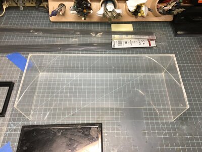
The model was on its permanent base and when I finished daily I would cover it with the acrylic dust cover. I was moving the cover, I wasn’t even trying to cover the model , just moving the dust cover, and I dropped it. When the cover hit my bench a large shard broke off the case and hit the mast, breaking it off once again! This time the mast broke at the joint between the upper and lower sections. None of the rigging broke, I was able to lift it back into place and make a repair. It is not pristine but it is together. I could have done without all the aggravation of multiple repairs but even with all the problems I still feel that the mast is much better than what came in the kit.

In the next installment I will look at weapons sub assemblies

IMG_1323.JPG


While I never took any photos of the damaged model here is one of the case. I glued the shard back in place so I could continue using the cover to protect the model.
 
Last edited:
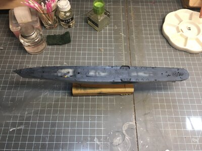
Part 8

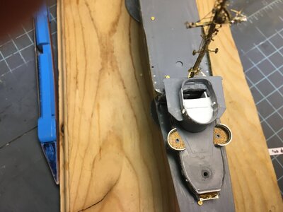
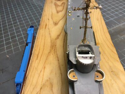
All of the weapons were taken from the Black Cat Round Bridge Fletcher set. I did need an additional 40 mm and 20 mm gun because of the aft gun tub and the additional 20 mm gun on top of the pilot house. I purchased two stand alone sets from Black cat to cover those extra guns. One of the minor problems with the Tamiya kit parts is they have the barrels centered, but they should be offset to the right of the turret standing on top facing front. The Black Cat parts are amazing, the guns are correctly offset, the mount rings are attached, (3 single knuckle and 2 double knuckle,) all the hand rails and ladders are attached and they even had the manual gun sights on top of the turrets.

5 Inch Mounts (2).JPGIn order to use the Black Cat gun mounts I had to fill the holes in the deck. The Tamiya Knuckles were cut off flush with the deck and glued in place. I did not use the polycaps.

5 Inch Mounts (4).JPG

Mounts 54 and 55, Mount 54 is unmodified but 55 has the Master Models brass barrel installed. The frame for the blast hood is in place. This was actually correct for the period but I found photos of hard late war covers and redid them.

5 Inch Mounts (5).JPG

Mount 55 is turned to port and you can see the offset gun barrel. If you look at Mount 54 closely you can see I have broken off the manual gun sight.

I added blast bags to all the guns and blast shelter covers for the gun captains of Mounts 51 and 55. The Tamiya kit parts did not feature these items either. From photo evidence the ship had blast bags installed during the Solomons campaign. And the gunner’s shields were actually the earlier wire frame type. I modeled those first and then erroneously corrected to the hard shell type. For blast bags I started with Tamiya tape and then used cut off hose reel rings, cut to make the support frames and then filled with sprue goo until they looked right. For the hoods I made a master and thermo formed plastic sheet. I used bare metal foil to model the ribs.

5 Inch Mounts (7).JPG

I have added the start of the blast bags here and a Tamiya gun mount is shown for comparison.

6th Dryfit (9).JPG

Mount 51 has the later style blast hood and by now I have had to replace all the gunsights.

The 40 mm guns were used just as they came from the kit they are wonderfully detailed as well with railings, seat and foot pedals on the base. All the boxes and conduits are exposed and the guns have the sights attached. The breeches are open and have shells. If you wanted these stowed you could cut the breech covers from the Tamiya parts and remove the open breeches from the Black Cat guns. I needed to make the second tub though. The Tamiya kit has an unused egg shape tub that would have be part of a lower tub on the aft deckhouse. There is no part for the lower style 01 level though, perhaps there were plans to make other versions of the Fletchers. They did make a kit of the Sullivans but I don’t know if it had parts in common with Fletcher. Anyway the unused tub was too thick and the bottom would have to be removed.
I was perfect to use as a form to make a new splinter shield. I used some strip with right width and dipped it into boiling water and formed it around the outside, making the seam on the aft end. I secured the shield with an alligator clip until it was cold. I glued a tab on the inside and when dry glued the shield together. I slipped the new shield over the form, upside down, and filed drain holes around the bottom. I took a piece of photoetch rail and detailed the inside of the tub as before. I added a grab rail around the outside and detailed with rolled tarps and ready ammunition. A couple of access ladders were placed forward one inside and one out.

Gun Tubs (11).JPG

The aft gun tub under construction.

I played with the location on deck dry fitting the depth charge racks, smoke generators and even had to move some hatches on the fantail. I found a photo of one of these tubs and it described the relocated hatches on the real thing also. When the locations were firm I glued a locating pin on the tub and the other parts so that it would be easy to assemble. I punched out two grating rings, one large and one small and glued these to the deck. The small ring was raised slightly with a 020” disc underneath. This would be where the director was. There was a railing around the director area to keep him from toppling off the platform, which I made from a section of railing, formed into a ring and soldered together.

Gun Tubs (12).JPG

The tub is completed, I left these two tarps unrolled to show the difference.

6th Dryfit (2).JPG

The finalized location of the gun tub showing the deck gratings and the relocated hatches and scuttles

6th Dryfit (3).JPG

The completed tub with a director and 40 mm base dry fitted

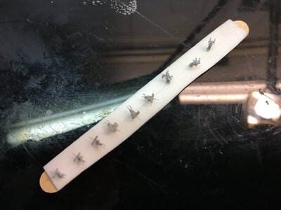
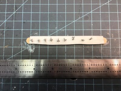
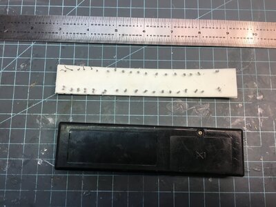
The 20 mm guns were very nice with ring sights, ammunition drums and very delicate adjusting wheels on the pedestal. I added shell ejection bags which seemed to be prevalent on 20 mm’s early in the war. Later it appears they removed them. (Maybe they filled up too fast). I made the bags from Milliput. These guns were fastened to a popsicle stick with mounting tape. They are so very fragile especially the sights and barrels. I had no evidence of 20 mm ready ammo lockers at each position but I added them as they came in the Black Cat set. I found the lids to be understated on these and I found photoetch doors that looked the part and added them. I even opened one lid after I found some video of the inside. https://ussslater.org/

Ready to Paint 06.JPG

The 20 mm guns and 40 mm directors

Ready to Paint 07.JPG

The torpedo tubes have some minor assembly. Each one must have the base added and the aft tubes need the crew blast shield installed. There wasn’t a ladder on the shelter so I added one per photos. The tubes have breeches that look so real you could open them and all the railings and controls are present. I thought it odd that the ladder wasn’t present but it was easily fixed. The depth charge racks and the K guns were used pretty much as is although I added the Eduard photoetch to the racks. I also had to drill new locating holes based on the plan view drawing. The kit hoists were detailed with wire and punched disc block and tackles. The hardest part of all this section was to avoid damage to the delicate parts and make repairs when I failed.

Ready to Paint 12.JPG

The parts for the K-guns

6th Dryfit (5).JPG

Depth charge racks on the stern. The flag staff, gun tub and smoke generators are also dry fitted.


I will cover the painting in the next installment.
 
Part 9

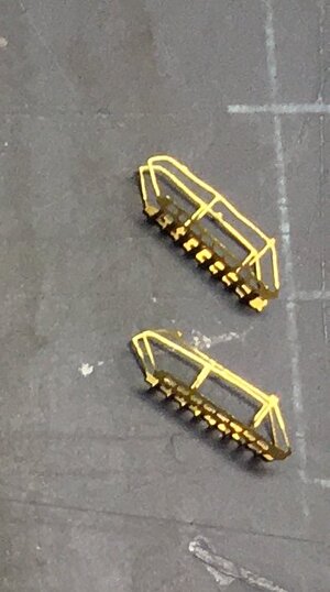
I know I said that I would cover painting in this segment, but I realized that I had left out some things on small parts like the port and stbd 20 mm gun tubs, the jack staff, the aft flag staff, life rafts, boats, propeller guards, propellers and the Mk-37 director. The Eduard gun tub splinter shields were annealed and formed with a round pin from a punch and die set rolled over the part to get it to curve. They were checked against the kit part. Eduard has relief etched the inside to show structural detail. The positions for these were set and round discs punched from L’arsenal photoetched grating. These parts were all glued in place prior to painting.

Gun Tubs (17a).JPG

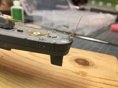
The jack staff was bent in the kit box and when I tried to fix it, broke it off the bow fairlead. I first tried to replace it with stretched sprue, but when I purchased the second mast kit I decided to replace it with the brass ensign staff. I spent some time making all the various railings including the main deck and I was able to add two bars of rail folded around the staff so it would join up with the forward sections of railing. I also added two support struts. The aft flag staff was made in much the same way, but it needed a shielded stern light which came from the mast set spares. The aft railing had netting added and it was glued to the staff. All the main deck railing had netting installed. The upper levels of the superstructure had the railings formed and glued to their respective pieces prior to painting. The main deck railing was not added at this time.

6th Dryfit (1).JPG

6th Dryfit (2).JPG

There were 6 life rafts, three to a side. Each pair was mounted differently. The forward pair was mounted to support struts for the forward 20 mm gun tubs. I made struts from photoetched scrap and the rafts were glued to them. The middle set was mounted to round frames which came up vertically at the deck edge and then angled to connect with the top of the main deck superstructure. Each frame had an angled cross strut. These were made from rod and the rafts glued in place. The aft set had a simple vertical frame also made of rod. Oars from a white ensign photoetch sheet and EZ Line lashings were added to each raft. The 26 foot motor whaleboats were from the Black Cat upgrade set. They were used unmodified.

5th Dryfit (15a).JPG

Life rafts mounted but no oars or lashings yet.

The kits davits had release pin marks that were filled with punched discs. I added “rope” made from fine copper wire and pulleys from punched discs. I added some L’arsenal rigging eyes for monkey ropes and the block and tackles. The block and tackle for swinging the davits was made from the same wire, eyes and White Ensign chain connecting links. I made a jig with two stiff wires glued about ½ inch apart to a block of wood. The eyes were inserted on the wires, glued, raised off the block. I wound the “rope” around the posts the way a block and tackle would be rigged and placed a connecting link over the first course of wire, completed the rigging and added a final eye to make the other side of the pulley. These parts were squeezed together and secured with a drop of superglue. The vertical wires were cut flush at the” pulleys”, freeing the assembly.

5th Dryfit (12a).JPG

I have just started working on davits here

The monkey lines were made with the wire, one horizontal line from davit to davit and 5 coiled and hanked “ropes” suspended on it. I made two sets of monkey lines, 4 sets of block and tackles and 4 more hanks of rope to hang from the bulkheads. I made rigging anchors out of scrap photoetch fret and eyes that were glued to points that would receive rigging from the mast. There are a pair off the roof of the pilot house, a pair behind the flag bags, a pair at the base of the aft funnel, and an eye on the forward side of the forward 40 mm director tub, eyes on the aft side of the forward 20 mm tubs and on the midship deckhouse just aft of the aft davits. The Black Cat Mk 37 director was not assembled until after painting. I removed the turret from its fret but left the dish on its fret until after painting. I had lost the first dish that I removed and I was just lucky that to sets were supplied.

The kit torpedo crane was modified with a base disc, brace, and scratch made arm. The kit part is solid and it should be open in the middle with one connecting joint in the middle and one on the end. I also made a chain fall with a carriage. 1/700 photo etch anchor chain, plastic strip and discs were used to make the chain fall. Several hose reels were assembled from Eduard parts and others were simply Black Cat parts.

5th Dryfit (14a).JPG

The torpedo crane, some hose reels and the last portions of the wave breaks on the midships deckhouse

Two of Tom’s Modelworks photoetched inclined ladders were folded up, I preferred these over the Eduard versions since the treads can be angled correctly. Eduard’s are solid. They provide a third ladder which was not used on Fletcher until later in the war. It would run from the forward port side of the midships deckhouse to the 02 level of the bridge. Fletcher had a vertical ladder on the stbd side of the midships deckhouse early in the war.

5th Dryfit (15b).JPG

The Black Cat kit had a 5 inch practice loader which would be located between the midships and aft deckhouses pointed to stbd. I made up a practice shell and powder charge and placed them in the breech. A second shell, charge and fusing station was added to a baseplate.

Practice Loader (1a).JPG

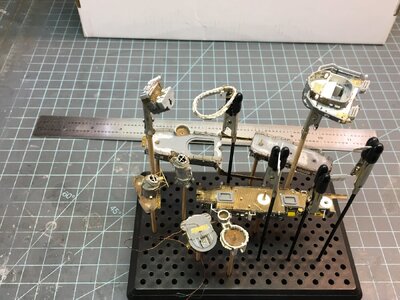
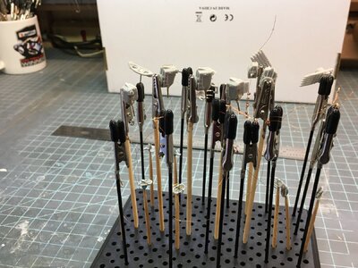
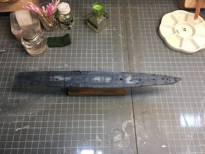
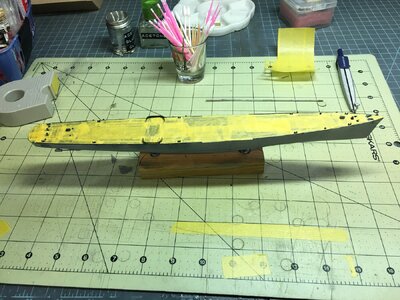
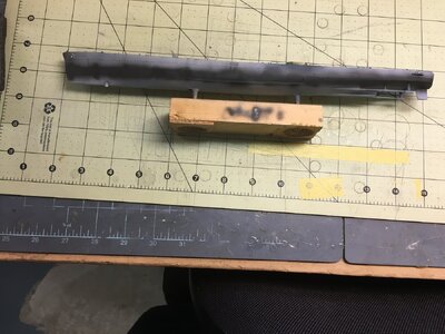
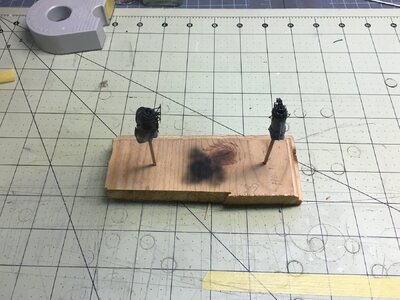
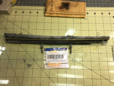
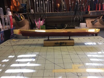
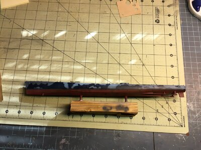
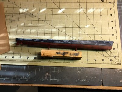
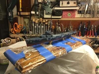
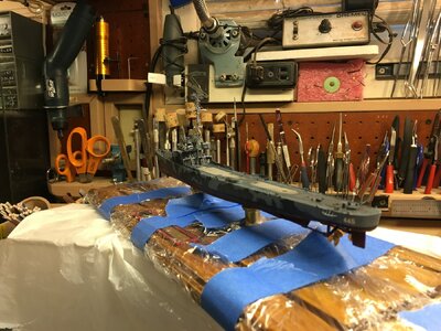
Now I turned to paint preparation. All the parts were cleaned in an isopropyl alcohol bath, or in the case of the hull and superstructure parts, sprayed with IPA through an airbrush. Everything was left to air dry overnight. I put them in a plastic storage box. I mounted the hull on a smaller block so it could be easily sprayed on the bottom. I set each superstructure part in its place and sprayed black primer around it. This clearly showed the area to be masked. I prefer to have bare plastic gluing surfaces when I assemble. So after the primer dried, those areas were masked off. Small parts were either clamped in alligator clips on a stick and kept in stands or stuck down on double sided tape on sticks, blocks or plastic strips

Ready to Paint 03.JPG

The black primer has been sprayed leaving the deckhouse outlines to be masked. The aft deckhouse is done. I haven't snagged my shirt on the mast but I'm about to.

Ready to Paint 15.JPG

Ready to Paint 19.JPG

Ready to Paint 05.JPG

Ready to Paint 16.JPG

After all the parts were masked, I sprayed a primer coat of Mr. Surfacer 1200, thinned 50/50 with Mr. Leveling Thinner on everything. Once dry I sprayed all the deck areas with True Color Deck Blue 20B 1942 +. I thinned this with their thinner although they say they are airbrush ready, it seemed a bit thick to me. I have always used enamel hobby paint and this was a different experience for me. I didn’t have any enamel marine colors and I wanted to be fairly accurate. The paint sprays fine and levels nicely. You of course have to lighten or darken with their paints. It does not brush paint very well at all and they do tell you this up front. It was somewhat inconvenient for touch ups. They also advise care with masking which gave me the impression that the painted surfaces might pull up with tape or were fragile. But I had few problems with that. I lightened the base color and highlighted some areas, and then I darkened the base color and sprayed welds and nonskid areas.

Masking and Painting (44).JPG

After this was dry I spent several sessions taping all the decks off. I used Tamiya tape, cut into strips and rectangles. I used Tamiya tape for all further masking jobs. Once everything was taped I sprayed the boot stripe with True Color Boot Black. I also did the top of the funnels. I masked the stripe off with 2 mm wide tape applied at the waterline. The funnel tops were also masked. The top of the hull was covered and the lower hull sprayed with True Color Norfolk 65-A Anti-Fouling Red. This was highlighted with lightened paint and then detailed with darkened color. I did this post shading on all the major surfaces as each color was laid down.

Masking and Painting (5).JPG

Masking and Painting (6).JPG

Masking and Painting (9).JPG

Masking and Painting (12).JPG

Masking and Painting (14).JPG

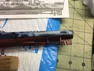
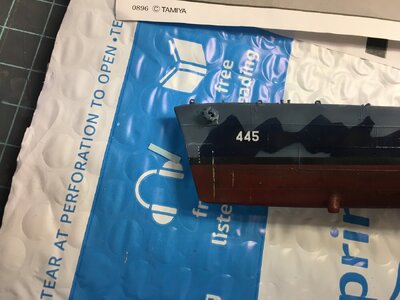
Then the upper hull masking was removed and the bottom covered. The upper hull was sprayed True Color Ocean Gray 5-0 late 1941. Portions of the main deck had been left uncovered, hatch risers, bitts, fairleads and the hawse pipes, these areas were also sprayed. Certain parts of the deck furniture were also painted now. I had to paint the breakwater in this color. This involved more masking since it was glued to the forward deckhouse. I wish that I had sprayed the entire superstructure with this color as it would have made masking easier. Instead I followed the rule of painting lighter colors first. I changed paint to True Color Haze Gray 5 H and all the superstructure elements were painted. After all this dried, the hull, gun mounts and superstructure all were masked for the second camouflage paint. On the hull Navy Blue 5-N blotches which carried up to the breakwater and main deck gun tubs. The upper superstructure was camouflaged with blotches of the Ocean Gray.

Masking and Painting (24).JPG

Masking and Painting (25).JPG

When everything was dry all the tape was carefully removed layer by layer. The only place I experienced any problems was on the metal breakwater parts. I used my finest airbrush needle and nozzle to touch that up freehand. I had few paint bleed problems but where I did I was able to carefully use a brush and fix them. I left all the painted parts to dry for a couple of days. When I came back I sprayed a thin coat of Micro Scale Gloss on everything. The hull decals were applied with the microscale system. I had to use Walthers Solvaset to get the Tamiya decals to lay down right. Some depth marks that I got from a Commander Series Models sheet went on with no trouble.

Masking and Painting (34).JPG

Masking and Painting (35).JPG

After this dried I prayed a second coat of Micro Gloss over the decals. I did all of the detail painting with my stash of Testors Model Masters Enamels. There was a lot of detail painting. This Includes painting some 75 sailors in khaki and dungaree uniforms. A coat of Microscale Micro Flat followed detail painting. I painted all running and standing lights with Tamiya Transparent Colors, Red, Green, Amber, (Yellow and orange 50/50) and Smoke. I lightly weathered with Thinned Tamiya Panel Line Accent Colors Black, Dark Gray and Brown. I did some oil paint filters and let everything dry again. Finally I sprayed a coat of Microscale Micro Flat.

Masking and Painting (39).JPG

Detail Painting (2).JPG
I had more detail shots but there is a limit on how many files you can attach.

I honestly think these true color paints are okay, they are pricey but what isn’t anymore. I will continue looking for enamels. I have tried to get Revell, Humbrol and Colour Coats but they are hard to find in the US and suppliers in the UK seem to be regulated against shipping to the states. Messing with the tinlet lids is a pain. I have heard that True North paints from the Midwest are good. They are pricey also but they have a good range covering pretty much everything Model Master did. I imagine if I could still buy Model Master they would also fit my definition of pricey. Those Testors 1/4 ounce jars that I got for 15 cents as a kid are over 2.50 a bottle now. That would make the Model Master jars around 5.00 now.

In Part 10 I will show the final assembly.
 
Part 10

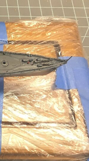
Assembly started by mounting the hull to the base and running the wiring up through the pedestals and out through the hole in the main deck. With everything loosely attached I lifted up the ship and put a dab of E6000 on both ends of the pedestals. I slowly tightened the nuts adjusting the positioning until the hull was oriented correctly and allowed the glue to set overnight. In the next session I covered the base with plastic wrap to ensure that during the assembly no spills or other misadventure would ruin the base.

Detail Painting (1).JPG

Detail Painting and Assembly (1).JPG


Assembly Begins (4).JPG


Assembly Begins (6).JPG

I glued down the lowest level of the forward deckhouse and clamped it. While it was drying I used some black foam under the pilot hose deck and in the aft compartment to eliminate light leaks, I glued the bridge crew in place, (4 figures,) then the pilot house overhead to the pilot house and clamped it. I positioned the two assemblies close together and connected the wiring testing it one last time to ensure it worked. When everything was dry the wiring was carefully fed into the ship and the assembled pilot house was glued in place and clamped. Imagine my surprise when I tested the circuit again and now it did not work! Eventually I traced the problem to the switch and replaced it with a different type.

I moved on to all the ground tackle on the bow and installed the anchors, chain, pelican hooks and chain locker covers. Finally after some test fitting I realized I had to install the mast now. The inclined ladders were glued in place and then the struts for the 02 level overhang. There were some small parts to round out the ground tackle and the forward davits to position. I added the block and tackle for the forward davits. I moved on to the forward railing and next the jack staff. I added a piece of EZ Line to it for a halyard. I rigged the main mast signal flag halyards. The stbd outboard halyard was a piece of detail wire so I could add a flag hoist later. Then I added any standing rigging to the pilot house.

Forward Railings and boat davits (3).JPG


Rigging (1).JPG


Rigging (3).JPG

I could now add the midships and aft deckhouses, so these were glued ln place and clamped. Once the clamps came off I installed the vertical ladder from the 01 level midships deckhouse to the 02 level pilot house. I did the funnels and placed the searchlights on the aft funnel. I placed the torpedo tubes and added the wave breaks around the midship deckhouse ladders. The aft davits and the whale boats were installed and rigged. Then all the life rafts were placed.

Rigging and Aft Deck House Completed (2).JPG


Midship and Aft Assembly.JPG


There appear to be no lifelines on the midships deckhouse. Any time the torpedo tubes might be used the life lines could be folded down. I did install one bar lifelines and folded them over when the glue dried. If you look closely they are there. There were some additional hose and cord reels and the deck winch were now installed. I placed 4 more figures on after con and the final two parts of the aft deckhouse were installed. Then the rest of the standing rigging was added. I had no rigging diagram so this is an amalgam of photos of various ships. I found the multiple insulators on some photos of the Kidd and I liked them so they were added. This is black tube acrylic paint added with a small brush.

Rigging and Aft Deck House Completed (3).JPG


Rigging and Aft Deck House Completed (4).JPG

I moved on to the midships railing then the K-Guns, spare depth charge racks and the hoists. Next the aft gun tub, depth charge racks, smoke generators, aft railings and the ensign staff. At this point I snapped the mast off again. It is not as true as it was but at least I was able to put it together again. I wish I could come up with a sure fire way to prevent this but no “aha” moments have happened yet. Oh yeah I could just be more careful.

Aft Railings, Gun Tub and Depth Charges Installed (1).JPG


Aft Railings, Gun Tub and Depth Charges Installed (2).JPG


Aft Railings, Gun Tub and Depth Charges Installed (8).JPG

I added all the 5 inch mounts all pointing off to port. Next gunners were glued to 20 mm cannons, and 40 mm seat positions. I added the barrels and 2 ammo handlers for each mount. The crews serving the two directors were also glued to their units. I then installed all the 20 mm guns and amazed myself by not breaking any of them. Finally the 40 mm guns and directors were installed. There are approximately 75 total crew figures about the decks. These were all supplied with helmets and vests as if at general quarters. They were a neck stiffening job to paint but I limited painting to two hour sessions and I believe they came out nicely. The Mk37 director was assembled and installed. All the guns and directors are pointed out to port.

5 Inch Gun Mounts Installed (3).JPG\

5 Inch Gun Mounts Installed (6).JPG


20MM and 40MM Guns (3).JPG


20MM and 40MM Guns (8).JPG

Finally I cut equal lengths of 2 sizes of brass wire for 5 in powder charges and 40 mm casings. I dropped them on the deck randomly and fixed them in place with diluted Micro Flat and a white glue mix. I used a Hawk Graphics (D3519) signal flag decal sheet for the WW II ensign and a flag hoist of the ship’s call sign. I understand that call signs were usually only displayed coming in, at anchor or leaving port but I did it anyway. The decals were applied to plain aluminum foil, one side at a time, wrinkled a bit and glued in place. Fletcher’s call sign was November, Echo, Bravo, Golf.

20MM and 40MM Guns (10).JPG\

Completed (3a).JPG


Completed (5a).JPG

That finishes this post and I will add some shots of the completed ship in the final installment.
 
Back
Top