Vasa 1628 – engineering a ship

Joined
Apr 26, 2023
Messages
383
Points
323

Location
European Union
.​
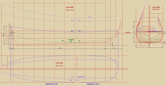
This graphical analysis took me just one day. There can no longer be the slightest doubt that even the famous Vasa 1628, although built bottom-first, is also the product of a well thought-out (albeit unsuccessful in this case) design concept and not some haphazard or chaotic construction on the basis – „we'll try to assemble something and then see what actually emerges”.

True, the design assumptions of the Vasa have quite a few flaws (combination of the too narrow and too high hull, insufficient volume of the underwater part of the hull, and still too heavy scantlings for these circumstances) and even the new set of specially cast lightweight guns, suitable for dynamic warfare on land rather than for arming a ship, did not help (on the other hand, the boarding doctrine of sea fight still in force at that time did not require guns capable of continuous, intensive fire).

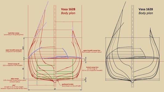
The design of the Vasa 1628 is conceptually uncomplicated and uses the simplest geometric forms, while differing in an interesting way from the other designs of Dutch origin already shown, in that here the „flat” had to be traced or drawn at the very end of the formation of each (leading) frame. Importantly, this order is completely opposite to the real stages of actual construction in the bottom-first method. This may imply that, in the case of the Vasa, the shipwright began his work by drawing complete plans first, that is, also including the contours of all (leading) frames.

Such a (conceptual) plan might have looked more or less like the attached diagram below:


ViewCapture20240211_022311.jpg

.​
 
Last edited:
An interesting analysis. We have noted that the bilge, futtock and breadth curves are very close to circular arcs over much of the length, with the futtock arc of fixed radius until near the ends. That the radii are simple proportions of main measurements of the hull makes sense. The actual shape of the hull and run of the planking does not suggest that there is a dead flat or straight section in any of the longitudinal curves, although the amount of curvature is very small andnow hard to analyze due to deformation of the hull.

I think that it is unlikely that there were any drawings, as they would have been difficult to convert to timbers. There is, in reality, not a single midships section as one would find in a hull drawn on paper. The longitudinal location of the maximum breadth varies with height, which is a typical feature of Dutch bottom-based hulls and not typical of ships built from drawings. Like other bottom-based hulls before about 1650 the frames are not parallel to each other or square to the centerline or a baseline. They are all skewed by slight amounts, which suggests that the floor shapes are determined from the planking rather than the other way around. The frames also lean at various angles. The farther forward or aft, the more the frames lean towards amidships, they are set more or less normal to the planking surface rather than oriented to hypothetical baselines. This is not very easy to predict in a drawing or convert into useful measurements for carpenters.

Examination of visible planking surfaces (both interior and exterior) in the bottom confirms that the bottom planking was assembled bottom-first. There is some evidence in the construction that there may have been a few floor timbers inserted early to guide or control the shape. There are five floor timbers which are much heavier than the rest and closer to perpendicular to the centerline. These are located at about amidships, at about where an Italian builder would put the "tail frames", and about halfway between these. These could have been used to control the deadrise while the bottom was being assembled. Once the bottom planking was set up, more floor timbers could be inserted. Once the bottom was stabilized, the first futtocks, based on circular arcs, could be inserted.

The primary stability issues are as Waldemar suggests, the hull is too tall and heavily built in the upper works for its displacement. The guns by themselves are not really a problem, they only represent about 5% of total displacement (most successful multi-deck warships of the 17th century have armament at 4-7 % of displacement). The guns on the upper deck and middle deck are higher than they need to be, due to excessive headroom in the gundecks. Given the average height of a Vasa sailor (166 cm/5'5"), the upper deck could be lowered about 30 cm and the middle deck about 20 cm without significant ergonomic effect. This would save many tons of structural weight, and would lower the center of gravity of the deck structures and the guns they carried. The deck structures themselves are also overbuilt, dimensioned to carry much heavier guns than the lightweight 24-pounders that made up the main armament.

The guns are actually a good compromise for shipboard use. They trade range for weight, but naval battles were not fought at excessive ranges in this period. They are perfectly capable of sustained fire, as our tests of a replica have shown, and are reasonably accurate (spread of shot at 1000 m is less than half the length of a typical large warship). They allow Vasa to achieve substantial firepower (broadside of 700-750 pounds) in a ship with 30% less displacement than a typical third rate of the later 17th or 18th century.

Their main weakness is not range, but long and inconsistent ignition timing due to poor touch hole arrangement. On a rolling gun platform, it is important to know when the gun will go off relative to the time that the match is laid at the touchhole. As an illustration of why this is important, at 1000 m, the exposed hull of a ship the size of Vasa is about 7 m high, and subtends an angle of elevation of 0.2 degrees. This means that the difference between a hit and a miss is a change in elevation of the muzzle of less than 1mm. This fine adjustment is possible, but the gun is mounted on a platform (the ship) which is rolling through several degrees, which spoils the accuracy of the gun if one cannot time ignition to with a fraction of a second. Also, at 1000 m, the point of aim in order to hit the hull is a point in the air about 10 m above the main truck. Shots at the hull only have a better than 50% chance of hitting at ranges of less than about 400 m.

I think that Waldemar's proposal on possible design avenues is certainly worth investigating. We have a detailed survey of the hull on which to base analysis. One question that interests me is how the builders might use geometric methods for predicting hull or timber shape without making scale drawings in advance.

Fred
 
.​
Many thanks Fred @fred.hocker for taking a look and your always valuable commentary.

I would like to address a couple of points raised.

Regarding the presence of dead flat in the central part of the hull, I must admit that finding the original design lines solely on the criterion of a potentially locally deformed curvature of the hull shape would indeed be a rather slippery undertaking. I therefore personally use a different, much more reliable method in such cases. For example, I try on various types of curves as line of the floor or line of the greatest breadth (e.g. arcs of circles, ellipses, logarithmic curves, etc.), move them along the hull and also modify their specific run and observe the differences in the distances between all the respective co-ordinates of these lines and the co-ordinates read from the source. In this way, the whole shape of the hull, not just some isolated and potentially deformed section, is involved in determining the run of the design lines. Incidentally, this is usually a rather tedious, multi-iteration procedure, but it is difficult to find another that is as effective.

The issue of canted frames on Vasa is also interesting. The point is that a slight, a few degrees inclination of the frames does not change the shape of the hull in any fundamental way. Thus, it is possible to imagine a situation where frames designed in vertical orientation were later actually erected at a slightly different angle (and even intentionally, e.g. for better correlation with decks or gun ports), and this with virtually no noticeable detriment to the ship's nautical properties. Actually, one don't even need to imagine this, because it was actually the case: especially in 18th century France (but also elsewhere and at other times), ships were quite commonly designed on level waterline (and thus with a sloping keel) and with vertical frames, but later, during actual construction, the frames were put vertically on the keel without reprojecting them for the resulting slightly different angle. My friend Martes and I have been looking for evidence of such reprojecting for very many months now (especially Martes has been particularly persistent on this matter), but so far we have not come across even one such case either in the French detailed treatises on naval architecture or among the dozens or even hundreds of plans we have reviewed for this. Apparently no one bothered with a difference measured in a few inches at most, and even then in the least important, highest parts of the hull.

Certainly, I do not know how it was in the specific case of Vasa 1628, but for the above reason, and several others, the mere fact of skewed frames on this ship does not, in my opinion, exclude the possibility of using previously drawn plans, partial or even complete. Such a plan could have been produced either on a reduced scale, on paper, or immediately in actual size on the mould loft in the shipyard. Personally, I do not subscribe to the view of the widespread use of paper plans in this period, but since paper plans were successfully used in later periods, what in practical terms could preclude their use earlier? I believe that the breakthrough in the widespread use of paper plans was only the introduction of diagonals and waterlines, both design and smoothing. It was simply no longer possible to proceed without paper, unlike in the earlier, 'non-corrective' methods.

Is it possible to design and build in an engineering way without using scale plans? Absolutely, especially if one takes into account hundreds, if not thousands of years of collective routine. For example, now, with some experience in the field myself, I don't need to know the contours of the frames to at least roughly judge the character of the ship, a glance at the longitudinal design lines is enough. And these longitudinal design lines can be perfectly simulated on the end view on the mould loft by some graphic devices like mezzaluna or similar.

As one becomes familiar with more and more material, the prevailing trend of using a couple of leading frames along the length of the hull becomes more and more apparent in the Northern tradition of this period, whereby the divisions practically used (that is, the specific number of divisions or even the divided element – the keel or, for example, the horizontal length of the line of the floor), could be quite individual in specific cases.

Artillery is also an interesting topic. Today, indeed, there is a great deal of emphasis on range when evaluating the capabilities of the guns of the past, but it is probably best to cite the example of Nelson and several other admiral-professionals who were quite cognisant of the effectiveness of firing from greater distances, always insisting on maximal shortening it at all costs, with the murderous efficiency we know. And battles fought at distances measured in many hundreds of metres ended with, at most, "a few sticks broken and a tooth knocked out".

However, I was more concerned with the weight of the cannons on the Vasa 1628. These 24-pounder half-kartauns have only the weight of fairly typical 12-pounder cannons, which means that after just a few shots fired in rapid succession a pause had to be made, otherwise various accidents would occur and even the guns themselves would be damaged beyond repair due to overheating. Not to mention the insane recoil of such lightweight guns (one can almost compare them with carronades). It is no coincidence that already shortly after the doctrinal adoption of gunnery tactics (replacing the hitherto dominant boarding tactics) during the First Anglo-Dutch War, drake-type guns, very similar in nature to the lightweight half-kartauns on Vasa, fell rapidly out of favour and were hastily re-cast into normal weight guns, in all fleets. The requirements in the field artillery could be a little different, as for the sake of sheer manoeuvrability they were often reconciled to a certain loss of tactical properties of the guns.

But what I really meant was that it was probably already realised at the time of building Vasa 1628 that fitting normal half-kartauns, i.e. of a typical weight for this calibre, on the ship was simply not possible or at least unsafe, hence the decision to cast a huge batch of a few dozen at a time, modelled after the field artillery specimen, specifically for the Vasa. Unfortunately (or should I say, fortunately :)), it didn't help anyway...

Waldemar

.​
 
Last edited:
It would be a very dilettante commentary, but I have a vague memory of an anecdotal story that the design of Vasa had several iterations before she was approved, with the King requiring to change the parameters of the hull. Does this - if it indeed what happened - show somehow on the hull as built?
 
.​
Correct at least in the sense that various alterations were indeed made to the ship during its construction (whatever the circumstances), about which Fred is naturally most knowledgeable. From my point of view, the most important information from the shipwright's testimony at a later trial is that he increased the originally designed hull breadth by one foot and five inches, a size too small to have any significant consequences for the proportions of the frame sweeps given above.

.​
 
Last edited:
A lot to answer here, so I am going to take this in several posts. First, alterations to the design:

It has become a popular modern myth (since about 1980) that the king meddled in the design after the ship was laid down, but there is no evidence for this. There was some discussion between the king and the master shipwright, via the admiral in charge of procurement, about the sizes and dimensions of the ships to be built according to the contract signed in January 1625, but once construction started, all of the evidence suggests that Vasa as built is the ship intended from the beginning in terms of overall dimensions, number of decks, etc. In a detailed survey and documentation of every timber in the hull (2008-2011) we could find none of the telltale indications of an enlarged or substantially altered hull. I can go into the details elsewhere if anyone is interested.

There were some changes made during construction. The contract specifies a breadth to the inside of the plank of 34 feet (10.10 m), and Hein Jacobsson testified at the inquest that he increased this by 1 foot 5 inches (0.42 m, although as an Amsterdam native, he might have meant 1½ Amsterdam feet, which would be about the same). This would give a moulded breadth of 10.52 m. As Waldemar notes, this is probably not a significant amount in terms of hull curvatures. However, the actual difference between the specification and the hull as built is much more. The moulded breadth of the hull at its maximum is 11.10 m, a full meter wider than the plan and more than twice the increase reported by Jacobsson. Could Waldemar see what difference this would make in the curves?

Other changes are less signficant, mostly detail changes to hatch locations and interior fittings, and the actual location of the mizzenmast appears to be about 1.5-2.0 meters farther forward than originally designed. The upper end of the sternpost was extended about 0.7 m, but we do not know if this was an alteration or just a response to wood supply.

Fred
 
Next, possible use of a paper or drawn design:

There is nothing in the design of Vasa that could not be drawn on paper if the designer wanted to work that way, but I see no obvious evidence that this was the case. Paper designs usually (but not universally) are turned into wooden reality in a way that leaves traces in the ship. In paper designs (or mould loft full-scale equivalents), the frames are usually of consistent scantlings and even spacing, they are usually set transversely square to the keel and vertically parallel to each other. As Waldemar points out, they do not have to be exactly perpendicular or parallel, and small discrepancies are removed in the process of fairing the frames before planking in any case, but large amounts of inconsistency introduce challenges in lofting the shapes and fairing the hull. In the case of Vasa, the frame timbers exhibit the following characteristics that are all uncommon for paper designs:
1. The spacing of the floor timbers on the keel is inconsistent, whether one measures from the forward faces, after faces, or centerlines.
2. The floor timbers are skewed transversely to the keel, by anything up to 4 degrees from square. This may not be a major problem as differences of up to 3 degrees or so do not introduce significant dimensional differences that cannot be corrected at the fairing stage, but it is atypical for paper designs.
3. The floor timbers are not evenly dimensioned. Not only do they vary from timber to timber, but individual timbers are often tapered in width. This complicates the lofting process. In ships built from paper designs, it is more common to see frame elements of consistent and even dimensions.
4. Futtocks are not attached to floor timbers; there are no made frames that would establish the entire section at any one point as far as we can tell. The sectional shapes would have to be built up in stages.
5. Futtocks are not always aligned well with floor timbers, so the sectional shape represented by one framing unit is not coplanar, again atypical of paper designs.
6. The vertical orientation of the frames varies along the length. Near amidships, the frame elements are more or less perpendicular to the keel, but towards the ends the frames lean progressively more towards amidships (as noted before, the frames are more or less perpendicular to the surface of the bottom planking, not the keel). This lean is not just a few degrees but becomes substantial at the stern.
7. The maximum breadths at each waterline do not line up in a coplanar section.

While almost none of these variations is insurmountable for the graphic design process, taken together they suggest that some other method was used to translate the designer's concept of hull shape (which was a complete three-dimensiona surface, not a bunch of intersecting lines) into individual elements. So on the whole I do not see evidence that this vessel is the product of a complete paper design laid out geometrically, either at scale or on a mould loft.

With that said, I do think that there was some thought given to establishing key sectional shapes in the bottom, through the use of a handful of controlling floor timbers (I mentioned these in my previous post). These are located at logical places to control the deadrise and bilge location for most of the length, and it would not surpise me if their shapes had been developed either on paper or on the loft floor according to some sort of rule or geometric progression. It is possible to analyze this, since we have detailed measurements of the hull form both before and after conservation and we have an accurate plan of the framing. So I might be giving Waldemar a call!

Fred
 
.​
Many thanks, Fred, for these explanations. Actually they are perfectly in line with my current view of the whole issue.

The first question that inevitably comes to my mind is related to the precision of the plans drawn up in 1970 and actualised in 1974 and 1981, as these were the basis of my work and consequently the conclusions to date. And more strictly, how well/poorly these plans reproduce the areas at the bottom of the hull, covering the contours of the 'flat' and bilge sweeps. Because nothing is as determinative for the geometric evaluation and consequently the eventual reading of the design/construction method as these very places.

If it turns out that the 1970 plans are not very authoritative, then it is certainly worth starting the search anew. It is so much valuable case...

Equally important may be the exact location of those unique floor timbers you mention, along the length of the keel, as it may guide to some specific and also hopefully correct solution. Even within any one method there can be so many sub-variants...
 
Finally guns:

The "lightweight" 24-pounders which form Vasa's main armament (46 of them on board when the ship sailed) are the Swedish variation on a widespread attempt in the 1620s to develop lighter guns, partly in response to improvements in gunpowder power and consistency. They are a product of the same kind of thinking that led to drakes and cutts in Britain: shorter or thinner-walled guns with the metal redistributed along the tube for better efficiency. In the case of the Vasa 24s, the guns are almost a meter shorter than the old long 24 they replaced, and instead of a wall thickness at the breech equal to the diameter of the bore, the wall is 3/4 of the bore This leads to considerable weight savings. The old long 24s weighed between 2000 and 2500 kg, while the new ones were in the 1200-1300 kg range, a savings of nearly 50%. This was still heavier than the traditional Swedish 12-pounder, which weighed around 800-1000 kg.

Because all of these lightweight guns fell out of favor relatively rapidly, modern scholars tend to underestimate their performance and overemphasize their failings. They were suited to the tactical environment of the time, which did not involve sustained artillery fire or long distances, and had plenty of hitting power. Our tests of a replica gun with live ammunition at full scale in 2014 showed the following:

1. Muzzle velocity with an equivalent service charge (modern powder has more total energy release than 17th-century powder and so charge size has to be reduced about 20-25% to get correct muzzle velocities) is in the transonic range, 300-360 m/sec, which is the same range which can be estrapolated from contemporary gunner's tables. Best perfromance for both range and accuracy is achieved at high subsonic velocities, since the transonic turbulence produced by spherical projectiles sucks too much energy out of the round.
2. Range on level ground with the gun at point blank elevation (bore elevation of 1.5 degrees from horizontal) is 800-1000 m depending on how well the ball fits the bore. We tested three sizes of ball which correspond to the largest, average, and smallest rounds found on the ship, with windages (difference between bore diameter and ball diameter) of 3 mm, 6 mm (considered optimum by 17th-century artillerists) and 10 mm. DIfferences in these windages can result in differences of up to 10% in muzzle velocity and thus range.
3. In recoil, the gun accellerates to a maximum of 3.4 m/sec (12 kmh) in about 0.2 seconds. Unchecked it will roll backwards on level ground 7-9 meters before stopping. There is insignificant decelleration in the first 3 meters of travel. Although this is slower than reported carronade recoil, the gun still covers the distance from ignition to the abrupt stop at the end of the breeching (1.5 m) in less time than a normal human can react to physical stimuli. So don't stand behind the gun.
4. At close range (less than 100 m), no wooden ship built in the 17th century would reliably stop a 24-pound ball. Our tests showed complete penetration of up to 90 cm of solid oak at a range of 30 m, and doppler radar measurement of longer range rounds indicates no significant decelleration in the first 100 m. Even at 1000 m, the ball will pass through a 12mm structural steel plate. At 100 m, chain shot fired with a half charge renders modern 25mm armour plate unserviceable, although it does not penetrate.
5. Maximum pressure achieved inside the breech is on the order of 75 megapascals (about 11,000 psi). This was a proof round, to reach 130% of working breech pressure to determine if the gun would be safe to fire. This resulted in no cracks or deformation.
6. Heat transfer from the burning of the powder is less than most people suppose. As one indication, the deflagration of the powder occurs so quickly that it does not consume the paper cartridge for the powder, and the base of the cartridge has to be extracted, singed but not burnt, from the breech after each round. This also means that relatively little heat is transferred to the tube. In sustained firing tests, with a round every four minutes or less, we were unable to generate noticeable temperature change in the tube, it remained cool to the touch. We could not even get enough change to extrapolate how many rounds it would take to get the gun hot enough to require a pause. This is very different from a musket. I shoot muzzleloading muskets in competition (.58 caliber Enfield pattern 1853), and the barrel is hard to hold after about 8 rounds fired at two rounds per minute. The main consequence of heating would be the expansion of the metal, which makes the bore smaller and the ball more tightly fitting, which reduces the amount of energy lost through the gap between ball and tube. If this windage is reduced too much, the ball may jam in the tube, preventing loading, or the breech pressure may exceed the safe limit of the gun. Historical sources indicate that this was a risk, especially with bronze guns, which swell more with temperature change than iron guns, but it would take sustained rapid fire to get to this point with this gun, probably expending more ammunition than ships normally carried in this period. Bronze guns do have the advantage that they are not adversely affected by cooling them by pouring water over them, which is more likely to cause stress fractures in cast iron.

Our conclusions after two weeks of sustained testing were that the guns of this lightweight type had more than enough accuracy, range and penetrating power for the ships they were mounted on and the tactical doctrine of the time. The heavier guns of the later 17th century could take higher breech pressures and thus generated higher muzzle velocities. The effect on absolute range was probably not as important as the flatter trajectory that higher velocities give. Guns could be aimed more effectively and reliably at ranges beyond 200 meters, and as gunpowder development produced ever more powerful formulations (especially after about 1780) guns had to be stronger to take advantage of the increased push.

We can see that the deck structure of Vasa is not designed for this gun, but for the older, heavier long 24s, while the gunports are sized for a mixed armament of 24s on the lower deck and 12s on the middle deck, probably an indication of the many discussions during 1627 about how to arm the navy's ships. We have at least seven different armament proposals for Vasa, which probably had some effect on the deck design. The beams are much heavier and closer together than necessary, as well as reinforced by oversized riders and knees. This heavy structure is one of the main culprits in the ship's high center of gravity. I am inclined to wonder if the designer, faced with an ever-changing proposed armament at the same time that the main bronze foundry in Stockholm was having trouble filling the order for an entirely new armament of lightwight guns, simply decided to make the deck heavy enough to carry anything the navy and ordance board eventually decided to issue to the ship.

Fred
 
.​
Many thanks, Fred, for these explanations. Actually they are perfectly in line with my current view of the whole issue.

The first question that inevitably comes to my mind is related to the precision of the plans drawn up in 1970 and actualised in 1974 and 1981, as these were the basis of my work and consequently the conclusions to date. And more strictly, how well/poorly these plans reproduce the areas at the bottom of the hull, covering the contours of the 'flat' and bilge sweeps. Because nothing is as determinative for the geometric evaluation and consequently the eventual reading of the design/construction method as these very places.

If it turns out that the 1970 plans are not very authoritative, then it is certainly worth starting the search anew. It is so much valuable case...

Equally important may be the exact location of those unique floor timbers you mention, along the length of the keel, as it may guide to some specific and also hopefully correct solution. Even within any one method there can be so many sub-variants...
Waldemar, the published plans are based on very accurate recording of the hull in 1963-1965. I can check these dimensions digitally, and can see that they recorded the shape of the hull as it stood then to within +/- 3mm. However, the drawings represent the reconstructed shape of the hull with the distortions present in 1963 removed or corrected. These distortions are greatest (or at least most noticeable) in the upper parts of the hull and the bow, but the outward fall of the stem and sternpost will affect the run of buttock lines, waterlines and other longitudinal parameters. The drawings also do not really take into account the fundamental assymmetry of the hull. The port and starboard sides differ in shape by up to 100 mm in places, and the center plane of the volume of the ship, derived geometrically, is offset to port about 50 mm or more. I do not actually know if the published plans represent one side or the other, or an average of the two. But the bottom line is that the variation from "reality" may be enough to make the determination of some design data a problem. As you suggest, it would be better to work from an accurate record of the hull, which we have in digital form.

There is another issue here that may be relevant. The workforce building the ship came from two different regions, with different systems of measurement and different boatbuilding traditions, and we can see that there are places in the ship where the same technical problem is solved in different ways. For example, the deck clamp for the lower gundeck is scarfed in a different way on one side of the ship than the other, which suggests different gangs of carpenters at work. This may have had some effect on larger construction/design issues,, so that, for example, the control frames were introduced as a way to keep carpenters not trained in the Dutch bottom-based method on track. As you say, so many sub-variants!

Fred
 
.​
Yes, Swedish guns, with a fairly universal purpose, were particularly light after Gustavus Adolphus' artillery reforms (quite the opposite of earlier practices), to the extent that elsewhere they would be rather classified just as light, especially field artillery, as opposed to heavier battery guns such as siege, fortress or naval guns.

I do, however, have a bit of a problem with the results of the test you have carried out in terms of the barrel overheating phenomenon. Most if not all artillery treatises of the period (as opposed to the works of modern scholars) explicitly describe this phenomenon, warn of its dangerous effects and give ways to avoid the associated troubles. My guess is that this rather dramatic discrepancy is due to the excessive quality of propellant used in modern tests, and not available at the time. Perhaps more as a curiosity: it was precisely because of the instantaneous overheating and consequent almost instantaneous decomposition that the famous Swedish leather cannons, already excessively light, became irretrievably gone after only one or two campaigns.

I also have a bit of a problem with the statement that the inner diameter of any pipe gets smaller when that pipe is heated. I always thought it was the other way around...

If the museum plans are as accurate as you confirm (and I would have had to do the distortion correction myself if it hadn't been done before by its authors), then I assume that the reconstruction of the design method shown above retains its value, at least until new relevant data becomes available. Great, many thanks once again.

.​
 
Last edited:
The 24-pounders used on Vasa were developed as mobile siege guns for the army, one could see them as lightweight heavy artillery, if that makes sense. Gustav Adolf then ordered them to be made in a naval variant for Vasa and its sister Äpplet. The order specified that the naval guns should be a foot shorter than the artillery pieces (so about 2.25 m from breech ring to muzzle instead of 2.65), but the foundry simply cast the artillery pattern with extra decoration but in the same size. Of the three guns we still have from the ship, two were cast specifically for Vasa in 1627, the third is an undecorated piece cast in 1620. As you note, they are very light for 24-pounders and so had limited range. They were not very popular with the board of ordnance, and no more were cast after about 1635.

Artillerists writing gunnery treatises certainly did warn of the overheating risks with bronze guns and I do not disagree with them. I am only reporting the results of a real-world test and pointing out that the heating of the gun is not instantaneous but requires sustained firing. Even if they are lightweight guns, they are still over a ton of metal which has to be warmed by very short exposure to heat energy over a relatively small surface area compared to the total mass of metal. My musket heats up faster because the surface area is huge in comparison to the mass and the amount of energy being released in a musket is much larger compared to the mass than in a cannon. The light 24s should heat up faster than the older type they replaced, since compared to the long 24, these guns have substantially less mass per unit of bore surface area. Perhaps as a more useful comparison, I can report that a bronze 6-inch infantry mortar (effectively the same size bore as a 24-pounder) that weighs only about 140 kg and uses a charge of only 50 g (compared to 2200-3300 g for a 24 pounder cannon) heats up noticeably after only seven rounds fired at three-minute intervals (I shoot these in competition as well). If we fired that at one round per minute it would get impossible to load before very long.

I do not think that the powder is a significant issue, but this is difficult to confirm since no one actually knows exactly how 17th-century powder behaves in the bore. Attempts to replicate early recipes have had, at best, mixed results. But the basic physics suggest that the deflagration rate of wet-incorporated corned powder from 1600 should not be that much slower than modern powder, and modern powder is made with very careful controls to prevent it burning too fast or detonating. Modern powder does release more total energy (more push) per unit volume, so in theory there may be more heat exposure with modern powder, although perhaps for a slightly shorter time. An interesting theoretical problem!

Thanks for the correction on the bore, you are correct that interior diameter expands as well as the exterior. Got my physics backward, ha!

I suspect that the latent heat properties of bronze guns were not a major problem in the tactical environment of the earlier 17th century, since guns were not fired in broadsides but as individuals and sustained firing was unusual. With the development of more effective broadside tactics in the mid-17th century, I imagine that overheating then had to be considered more seriously.

I think that the plans you are using are probably good enough for an initial appreciation of possible design methods, and I will be interested to hear what you discover.

Fred
 
I can add about the famous (and famously aweful) leather guns that the heating issue was especially bad because they have very little mass relative to the heated surface (compared to proper metal guns) and one of the key materials, leather, suffers permanent loss of strength at much lower temperatures than any common gunfounding metal. Drying your wet boots in front of the fire is a good way to ruin them, so the result of pouring fire through a leather tube should not surprise anyone!

Fred
 
.​
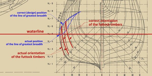
... well, having recently worked with the Hohenzollern model hull drawings, which were very distorted by today's interpreter, I assumed that distortions of today's origin, of a similar nature and magnitude, also have the published plans of the Vasa. This, by the way, is a fairly normal circumstance. Consequently, I corrected the lines drawn up by the museum staff in a way that would have to correspond to a correctly designed and built ship. This corrective treatment concerned a fairly extensive area across the entire aft half of the hull roughly at the waterline and beyond. In this way, I have reconstructed and shown above the ideal state of the construction, or in other words the design intentions, which, incidentally, for me personally is even more interesting than the features of an already made object, usually burdened with various manufacturing, operational or time-related defects.

Now, thanks to Fred's confirmation that the 1970 museum plans do indeed correspond very well to the preserved hull geometry, I have realised what a terrible mistake was made not so much by the ship's designers, but more likely by the workers actually building the ship (although the master shipwright overseeing the work should have spotted this and corrected it accordingly if he knew his trade).

The point is that in the bottom-first method, once the 'flat' had been made and the scheergangh/scheerstrook (i.e. a properly shaped beam – the physical equivalent of the geometric line of greatest breadth) hung, it was time to erect the futtock timbers. According to the design rules, but even more so to requirements of a hydrostatic nature with extremely momentous consequences, these futtock timbers should be positioned so that the point of their greatest lateral spread coincided precisely with the height of the scheerstrook at that point. This way guaranteed, in a properly designed ship, the greatest breadth of the hull was always above the waterline, which was particularly important for tumblehomed ships. Meanwhile, sloppiness on the part of the workmen meant that the largest spread of the futtock timbers over a significant length of the hull effectively fell well below, in some cases even below the draught line, with terrible consequences. This is probably the worst thing that could have happened, worse than any other cause of disaster taken singly. Or it may not be the sloppiness of the workers at all, but rather the disastrous manner in which the ship was widened by master shipwright, which he testified about at the trial. If so, he could not have done worse.

The importance of the correct relationship of the line of greatest breadth to the line of draught was already well known to professional shipwrights at the time, as is quite evident from, for example, the so-called Newton manuscript, which I personally date roughly to the second quarter of the 17th century.

For the sake of brevity, I will no longer give a lecture on hydrostatics, this is a rather specific subject, but at the same time easily accessible elsewhere to those interested, I will limit myself here to a graphic illustration of the circumstances described above.


ViewCapture20240213_002647.jpg

.​
 
Last edited:
Very interesting! I have now done a quick check of the current digital data of the hull shape as it sits in the museum today (as well as the documentation of the hull form prior to conservation), and the anomaly that Waldemar has identified is present on both sides in about equal measure. The effect is that the lowest point in the line of maximum breadth is about 14-16 meters abaft the nominal midships section, and is about 0.35 m below the height of the max breadth amidships. At its lowest point, the breadth line is about 0.12 m below the load waterline as reported at the inquest. The LWL has to be taken as approximate, since the graduations in the draft marks are only at ½ foot intervals, so I would say that the LWL is +/- 0.075 m. Even allowing for this, the breadth line still dips below the LWL over about 10 m of the length of the hull The breadth line is not a smooth arc, but has a long flat in the middle of the length. The hull is more or less fair, so the dip is not an artefact of distortion after construction but was part of the built shape.

This would have a negative effect on stability, as Waldemar notes, although I am not sure that I would agree that it is the single greatest cause of the sinking. The sinking is a result of an error chain rather than monocausal, and in a modern investigation, the largest blame for the sinking would probably fall on the admiral who ordered the ship to sea after it had been demonstrated to him that the ship was unsafe. I would agree that the shape contributes to making the ship unstable, and the specific effects of this kind of anomaly would help to explain the observed behaviour of the hull during the sinking. The ship heeled to port at least 12 degrees (the minimum amount needed to bring the sills of the lower ports under the water) and achieved equilibrium, not heeling further but not righting itself. Congratulations to Waldemar for identifying a specific feature of the hull form that is significant but has not been previously noticed!

Stability is not, however, determined solely by hull form. The low breadth line means that the the normal movement of the center of buoyancy to the low side of a heeling hull is reduced (we can go into the math if anyone wants), which reduces the righting moment. However, the center of buoyancy works in relationship to the center of gravity rather than alone. If the center of gravity is sufficiently low, the result will be uncomfortable but not necessarily catastrophic. Many of the typical hull forms of the 17th century had low form stability compared to modern vessels and depended on competent ballasting to be seaworthy, especially in ships with multiple gundecks. Many multi-decked ships built by competent designers suffered from poor stability behaviour when first put into service and required remedial measures, such as girdling, cutting down the rig, and redistributing armament. Is the low breadth line a decisive or overwhelming factor or one of several contributing factors? Is it possible to quantify the difference it makes?

In the case of Vasa, the poor form stability (made even worse by the breadth issue Waldemar has identified) was combined with poor weight distribution in the basic structure, with upperworks too tall and heavily built relative to the total displacement. We can say that the ship's master, Göran Matsson, was correct when he testified at the inquest that he had ballasted the ship as deeply as he dared. I think he was aware of the limitations caused by the low breadth line.

I wonder with Waldemar if the odd shape in the after part of the hull is a result of the widening of the hull rather than the initial design. The builders were working with timber that had been roughly shaped to patterns in the forest, and so had limited wiggle room when they widened the ship. If the transom was already up, as was a typical early step in bottom-based construction, the wider hull amidships would have to be faired to meet it, since there is no evidence of packing out the fashion pieces. This might have required leaning the futtocks in farther than planned in the after part of the hull. If one draws a similar but narrower midships section (basically a narrower floor flat but similar bilge and futtock sweeps), closer to the initial design breadth, and plots a breadth curve, can it be run fair and rising all the way from amidships to the transom with the sme futtock shapes? Waldemar, would you like to give that a try?

Fred
 
No, Vasa is not a verlanger (a ship cut in half amidships and lengthened). There are archaeological examples of that kind of alteration so we know what they look like. Vasa is the length it was intended to be, within a meter or so. It is also the height it was intended to be from the earliest design discussions, the major change from specification is in breadth.

However, I think that it is possible that the point of departure for Hybertsson's original design was his experience with single-gundeck ships, of which he had built several successful examples in the period 1603-1626. The design development method before the discovery of calculus and the mathematical tools we use today for evaluation of paper designs was to start with a proven good design and make incremental changes based on empirical evidence. In Hybertsson's case, he had no good departure point. As far as we can tell, he had never built a ship with multiple gundecks before, so he was working well outside his experience and comfort zone. Vasa's hull shape looks a lot like a single-deck design which has been stretched upwards and then overbuilt to compensate for the heavier deck loads, a fatal combination. Having looked at the drawings and the ship again today, I think the problem with the breadth line is tied to the alteration in width.

This does not mean that it is simply a matter of adding another deck to an "original" single-deck design. The deck shapes and structures are well integrated and thus parts of a coherent design, even if that design is seriously flawed. Based on the timber shapes and the methods used by the yard to convert trees to frames, I believe that the initial design, which was written down in the contract specification as just two dimensions, keel length and maximum breadth, was for a narrow, tall ship. This design probably generated the patterns which were taken to the forests to select and rough shape frame timbers during 1625 (as reported in the shipyard's account books, whcih survive). Once the timber was roughly shaped, the choices available to the shipwrights were limited, as Hybertsson explained repeatedly to the king in correspondence in the autumn and winter of 1625-1626, before the keel was laid in February or March 1626. Hybertsson reported already in the autumn of 1625 that he had all the timber ready for the first ship of the contract (Vasa).

A key question is at what point did Hybertsson, and then his successor Jacobsson, decide to widen the hull? Whether they thought the original design was too narrow or too tall, the only real option for changing the hull shape without wasting expensive timber was to make it wider by making the bottom wider. The floor timbers, if they had been cut overlength, would reach to an extra bottom plank or two and the first futtocks, which are L-shaped, could be shifted outward on the bottom planks, but it would be difficult to make the ship taller once the bilge, futtock and breadth sweeps had been imparted to the first and second futtocks. If the decision to make the hull wider was made after the transom had been erected and assembled, then the widened hull would still need to turn into the original narrow transom, and one way to accomplish this with the timber already cut could be to lean the futtocks inward slightly in the space between amidships and the transom. There was less of a problem at the bow, since the hull has to turn into the stem in any case, but the breadth line forward of amidships is also a little wonky, not a fair rising curve.

So here is the potential check. If one starts with a midship section that has the same futtock and breadth arcs, and perhaps even the same bilge arc, but has a floor flat about a meter narrower, can one make a fair hull with the same frame timbers that has a better, more typical breadth line? This is the kind of question where Waldemar's wizardry on the computer can be really helpful.

Of course, that initial design is probably even worse. It will displace at least 100 tonnes less and be proportionately even taller for its breadth, with very little reduction in topside weight. So the builders probably had the right idea, but did not manage the execution of that idea very well.

On a side note, I went out to the ship hall today and looked at the hull to see if the ugliness in the breadth line is visible, but it is pretty well disguised by the strong visual cue of the lower wales, which run fair (and as Waldemar has shown, in smooth arcs). At the midships section, the maximum breadth is at about the height of the third wale from the bottom, and because the wales rise in smooth arcs, one would expect them to follow the breadth line. The breadth line should coincide with the third wale most of the way, if not all of the way to the stern, but it drops down to the second wale before following it to the stern. This is actually hard to see on the ship itself, but not impossible.

Looking forward to see where all this goes.

Fred
 
Back
Top