• SUBSCRIBE TO SHIPS IN SCALE TODAY!

    The beloved Ships in Scale Magazine is back and charting a new course for 2026!
    Discover new skills, new techniques, and new inspirations in every issue.

    NOTE THAT OUR NEXT ISSUE WILL BE MARCH/APRIL 2026
  • Win a Free Custom Engraved Brass Coin!!!
    As a way to introduce our brass coins to the community, we will raffle off a free coin during the month of August. Follow link ABOVE for instructions for entering.

Vlieboot »De Zwane« 1592 — Barents discovers the Arctic

Joined
Apr 26, 2023
Messages
860
Points
403

Location
European Union
.​
Encouraged by @Heinrich , who also provided me with interesting and essential source material — in particular, relevant contracts for the construction of vlieboots from the last decade of the 16th century, transcribed by Menno Leenstra — I decided to undertake a conceptual reconstruction of the vlieboot “De Zwane”, part of the fleet of the famous explorer Willem Barents. Significantly, the ship chosen for Barents’s difficult mission was regarded at the time as the best seafarer in the region, and the choice of such a vessel is hardly surprising, given the completely unknown waters and winds through which it was to sail. Heinrich chose not to impose anything regarding the reconstruction itself, despite my invitation to actively participate in this exercise; nevertheless, he suggested including this introduction from a work by Menno Leenstra, discussing the history of the vessel and its crew members, as well as the inventories relating to its preparations for Barents’ polar mission:

Well-known Dutch historian and expert translator of 17th century Dutch manuscripts and transcripts, Menno Leenstra, argues that the “Vlieboot” Zwaan which was used in both Dutch expeditions to the Polar Regions in 1594 and 1595 is, in all likelihood, the best example of what Willem Barentsz’s ship could have looked like during the 1596 expedition. This is courtesy of the fact that considerably more is known about this ship than what has been published to date.

The expedition to Waygats in 1594 was originally organized by the merchant Balthasar de Mucheron, who had moved from Antwerp to Zeeland. After he sought support for this expedition from the States of Holland and Zeeland, the organization and leadership were taken out of his hands by the States General, largely against his will. The States General, in turn, commissioned the outfitting of the ships from the admiralties. As a result, a lot of information about the ship De Zwaan, which was on the account of this admiralty, can be found in the preserved accounts of the Admiralty of Zeeland. Since payments for costs made in the "preparatory phase" were also made by this admiralty and Mucheron submitted a detailed account for this, some details about it can also be retrieved from this administration.


* * *​

The conceptual reconstruction of the vlieboot ‘De Zwane’ will be based in particular on a contract for the construction of a vessel of this type dating from 1592, which contains most of the key numerical data and which, amongst a number of other surviving shipbuilding contracts from those years, is considered to relate specifically to the vlieboot ‘De Zwane’.

It should be noted here that previous ship reconstructions, based on these early Dutch contracts from the turn of the 16th and 17th centuries, have not been entirely successful, as they have encountered a difficulty in interpreting the numerical data relating to the hull height that has so far proved insurmountable. The point is that the values given in these early contracts were interpreted in a manner now accepted for later decades, so to speak within a structural rather than a conceptual paradigm, which did not allow even generally correct hull proportions to be obtained; in particular, the ships would have had far too little draught in relation to the height of the superstructure (they should be more or less equal), nor would it be possible to add the ‘mandatory’ weather deck above the main deck (whether in the form of a light grating deck or a slightly more robust koebrug), even at the cost of bringing the gun ports right down to the waterline!

On this specific point, a solution is therefore proposed that is closely based on the recently identified Dutch design methods within the broader Northern tradition (illustrated, for example, by the design of the frigate Wageningen 1723, https://shipsofscale.com/sosforums/threads/dutch-frigate-»wageningen«-1723-—-a-couple-of-decades-ahead-of-chapman….18387/), which resolves the previously insurmountable problems mentioned above. Indeed, the proposed solution coherently reconciles all the fundamental requirements for this case (and others):

— a depth of the submerged section no less than that of the unsubmerged section of the hull in the midship region, which is one of the most important factors influencing the weatherliness or its lack of a seagoing vessel,
— sufficient height of the hull’s above-water section for a double-deck configuration,
— the correct position of the hull’s maximum breadth in relation to the waterline from the point of view of the ship’s transverse stability, a circumstance known to shipwrights of the time (here a fairly typical distance of 2 feet above the waterline),
— sufficient distance of the gun ports from the waterline (here 4 feet, suitable for smaller and medium sized vessels of essentially non-military purpose).

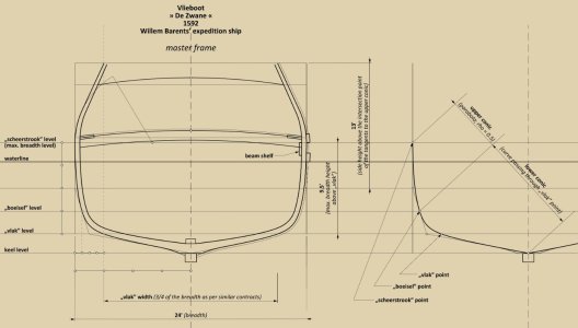
Furthermore, the proposed interpretation has a direct impact on the shape of the master frame itself, in a sense facilitating the identification of its realistic contours, as intended by the vessel’s designer (note: nevertheless, some elements defining this contour, such as the position of the ‘boeisel’ point or the extent of the tumblehome, still had to be inferred; similarly, the width and height of the ‘vlak’ were proportionally derived from other contracts of that decade for vessels of the same type).

Strictly speaking, this is only the beginning of the work, but I think that the initial results can already be presented. Hopefully, the diagram below is clear enough in itself and requires no further explanation; nevertheless, it should be clarified that the proposed interpretation of the following provisions in the contract is as follows:

„… diepe derthyen voeten” (depth 13 feet) as — the side height above the intersection point of the tangents to the upper conic,

„… de bantwegers […] gelecht aen weder syden aen boort, op negen ende een halve voeten...” (beam shelf fixed on both sides at a height of 9.5 feet) as — max. breadth height above „vlak” level 9.5 feet.


001.jpg


.​
 
Last edited:
Dear @Waldemar and Friends

When I obtained the contract (bestek) from the Zeeuws Archives (thanks again, Michiel van Wijngaard), you can well imagine my elation. It was the culmination of more than four years of research on the ships of Barentsz's expeditions. However, having five pages of old-Dutch transcript does not relate to anything tangible. The contract had to be interpreted and transformed into an actual format which could not only provide an insight into the build of late sixteenth century Dutch ships but could also potentially serve as the means and basis from which a model could be constructed. From the outset I knew exactly whom I had wanted to approach for such a task and to my delight, Waldemar shared my enthusiasm for the project.

The reason why I don't want to say anything about a potential reconstruction at this stage is simply because it may be quite a while before I can get around to that. So, to start a build log at this stage, would simply be premature.

Waldemar ik ben benieuwd!
 
.​

For those interested, at the current stage of the reconstruction, the most relevant sections of the contract are as follows:


Inden eersten sal de kiel lanck wesen tweeenvyftich (52) voeten, dicke elf (11 duymen) aertbrekens (voren binnen ende achter buyten) sonder de yelinghe van een stuck, ofte met een voorloop, tot contimente vande Besteders, int midden breet 14 duymen, voren ende achter naer den eysch.

Den voorsteven lanck 27 voeten, met 4.5 voeten bochts, dicke 12 duymen, breet 28 duymen met 11 voeten vallens.

Den achtersteven lanck 19 voeten, eenen (1) voet bochts ende 6 voeten vallens beyde ghesloten met behooren slimphouten.

[…]

Dit schip sal wyt wesen op syn mastghebint 24 voeten voren ende achter naer des besteders beliefte, diepe derthyen (13) voeten.

[…]

Den bantweger dicke 3 duymen, breet zestien duymen ghelecht aan beyde zyden aen boort, op negen ende een halve (9.5) voeten hooghe, ende voorts alle de andere weghers op 2 duymen blyvens, opden zelven bantwegher salmen legghen 14 binden elck een voet vierkant ende elck met 2 behooren knien ghesloten, de zelfde met zoveel bochts naer des besteders beliefte.

Opdezelfde binden zalmen legghen 2 gancboorden, dicke 4 duymen, breet 18 duymen daer ane ghevrocht over elcke zyde twee eycke plancken dicke 2.5 duymen, breet elck 14 duymen ende den overloop voorts toeghestreken met goede, drooghe pruysche delen, alle blaucant gheweert, die wel dichte gheschaerstok ende gheribbet met goede viercante ribben wel dichte de maeckelaers ende Luycken ghemaect naer des besteders zin.

[…]

Voorts achter salmen maecken een Cajute, 2 voeten neertrappende, ofte daer ontrent, beneden den overloop, ende dat in forma ghelyck voorts de Boot van Cap. Cornelis Leynsz. ghetimmert is, achter met een vast bouchnet, voren met een vaste voorcasteel ofte cabuyster over t’soch.


* * *

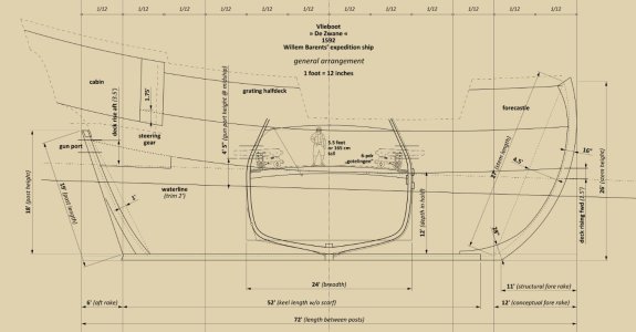
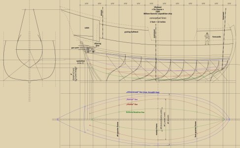
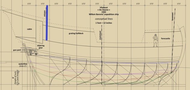
The attached illustration, which can be seen below, is a preliminary, simplified conceptual sketch, arranging the design elements graphically in accordance with the data contained in the contract for the construction of ‘De Zwane’, partially supplemented with dimensions taken from contracts from the same years (i.e. 1592–1594) for vlieboots of the same size.


003.jpg


First and foremost, it will be argued that the true length (between the posts) of Barents’ vlieboot was not 69 feet, as obtained in previous reconstructions by simply adding together the lengths of the keel and both rakes specified in the contract, but 72 feet.

Adopting this second value, which is three feet greater, means that the reconstructed vlieboot has ‘standard’ hull proportions – precisely 6 : 2 : 1 (length : beam : depth), or, if preferred, 3 : 1 : 1/2; furthermore, both rakes are round sub-multiples of the hull’s breadth (namely 1/2 and 1/4 for the fore rake and aft rake respectively).

Or, expressed in dimensions:

Breadth (moulded) — 24 feet
Length (between posts) — 3 x breadth = 72 feet
Depth in hold (from keel to deck) — ½ x breadth = 12 feet
Fore rake (from fore vertical to stem rabbet) — ½ x breadth = 12 feet
Aft rake (from aft vertical to post) — ¼ x breadth = 6 feet

A possible reason for this apparent discrepancy in total length may be that the keel length was taken from the design drawing and specified in the contract only for that part of it which had a full cross-section, that is, without taking into account the scarf that joined the keel to the stem, and this is clearly not an isolated case where the sum of the keel and both rakes does not match the stated overall length.

Furthermore, the stem rake was most likely taken from the design drawing (and its value recorded in the contract) in the same way as the stern post rake is measured, that is, structurally rather than conceptually, i.e. for the latter — to the rabbet line (see diagram).

Generally speaking, it can also be noted that this method of notation — which is not so much arbitrary as it is one that overlooks conceptual issues and focuses in particular on clearly visible and, as a result, well-understood structural, fitting-out or decorative matters — is predominant both in the written contracts of the time and in today’s descriptive commentaries, even by experts in specialist publications discussing design drawings from the era. The very few exceptions essentially confirm this, it seems, ever-relevant phenomenon.

In this reconstruction, for the assumed deck height of 6 feet, the hull height at midship equals the ship's draught, the stern height is equal to twice the draught, and the height of the forecastle is equal to one and a half times the draught, which is almost perfectly consistent with the general, categorical recommendation in the so-called Newton manuscript from the first quarter of the 17th century, naturally closely related to the ships’ weatherliness and transverse stability.

Contracts from those years specified the length of both posts, measured diagonally relative to the keel (see diagram). Their height, measured vertically and also shown in the diagram, is the result of an appropriate conversion.

In the reconstruction, the deck rise in the aft section of the hull (3.5 feet) and the trim value (2 feet) were selected such that it proved appropriate to incorporate a step in the deck with a height of ‘approximately’ 2 feet, as mentioned in the contract, for a logical arrangement of the stern section, with particular regard to the steering gear, for the stern post length of 19 feet specified in the contract (which translates to 18 feet in height).

The dimensions and height of the gun ports above deck were selected to accommodate 6-pounder cannons, as this appears to be the maximum calibre of the guns issued as part of the ship’s preparations for the expedition, judging by their weight as stated in the ‘De Zwane’’s’ outfitting documents (1,600 pounds).


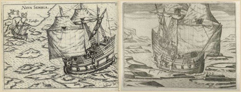
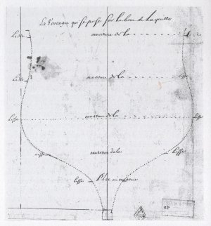
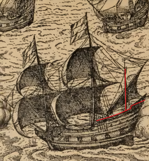
Below, two engravings depicting a vessel from Barents’ expedition, showing the mizzen mast in front of the cabin and also in front of the helmsman’s station, which allows for the mizzen mast to be stepped on the main (lowest) deck:

004.jpg


* * *​

If anyone has any substantive comments on this matter, now is a very good time to share them. Incidentally, judging by the content of the inventories provided by @Heinrich — which appear not to have been exploited in previous reconstructions — I expect that this is not the end of the surprises regarding the features of Barents’ vlieboot .

.
 
Last edited:
Dear Waldemar. Now you have really me excited for a variety of reasons!

I know that what I am about to post is going to sound very unscientific and illogical, but when you have been busy with a particular type of ship for as long as I have and have been exposed to the number of renderings that I have, you start developing develop a certain "gut feel" of what the model should look like. The moment that I laid my eyes on your rendering; I knew that this was it!

There are three points I would like to mention in particular. Firstly, the draught of the ship is considerably deeper which adds proper substance to the hull. No longer is the height between decks 1.4 or 1.5 meters which would have been nothing more than a crawl space. Secondly, the substance makes the build-up around the forecastle area look much more integrated with the overall hull design than on any other interpretation. This was something that irked me on both the iterations that I built - the forecastle always looked like an add-on, never as if it was part of the ship. Lastly, gone is the exaggerated high build-up at the stern which would have posed serious concerns about the weatherliness of the ship.

The one aspect that I have to wrap my head around and which is new to me is the difference between the structural and conceptual dimensions. I simply cannot believe the impact that it makes on how the model is perceived. I am, however, slowly getting there (remember you are dealing with an English teacher; not a draughtsman or engineer!)

Lastly, you are so right when you say that the contents of the inventories/contracts have never been explored before - and goodness knows why not. They have always been there - all that was needed was proper research!

Well done, Sir!
 
Last edited:
I’m very impressed how you managed to translate the old Dutch bestek into drawings. Even for a Dutchman 16th century Dutch is not easy to read. To translate that into technical drawings is yet another feat. Well done!

I would like to warn you, however, that you need to be careful in interpreting the measures “voet” and “duym” from that time. They certainly do not directly translate into current-day US feet and inches.

The lowlands had about as many different types of “voet” measures as there were cities, ranging from some 27 to 33 cm in length. While this does only result in a scale error, a secondary complexity is that a voet could be subdivided in 10, 11, 12 or 13 duymen, depending on the region. For example, the Amsterdamse voet was 28.3 cm and was subdivided into 11 duymen (not 12).

I hope that this information is of assistance to you in your work. I encourage you to check which measures were used in the bestek, which regional feet were meant.

Veel succes!
 
Last edited:
.​
I would like to warn you, however, that you need to be careful in interpreting the measures “voet” and “duym” from that time. They certainly do not directly translate into current-day US feet and inches.


Thanks so much for your post. Well, actually, in this kind of undertaking, there’s no problem at all with converting the original values specified in the contracts to metric units, let alone to today’s US feet and inches, since such a conversion is not only unnecessary but would actually hinder the reconstruction work and obscure the picture.

For example, if a contract specifies the hull’s breadth as, say, a round 24 feet of the locally used foot, then in my reconstruction project it simply remains 24 feet, and the hull’s length—which is three times the breadth—is a round 72 feet. This is much clearer than, say, after a possible conversion — 23.622 in breadth and 70.866 in length of some other foot. So why convert these values to some other unit of measurement?

For these reasons, there can be no question of any “scale errors”, since no scaling is being performed.

If inches are also used in a contract — which is almost always the case — the only thing one need to know is how many inches are in a foot to get the correct ratio between the two. These specific contracts for building vlieboots are from the southern Netherlands, so it’s safe to assume that one foot equals 12 inches, and this information is already included in the header of my diagrams. This is confirmed by the measurement of 11 inches, which sometimes appears in this group of contracts for the construction of vlieboots. If the foot were 11 inches long, as is indeed the case with the Amsterdam foot, for example, the text would likely read “one foot” instead of “11 inches”, and the value of 11 inches would possibly never appear. This is one of the first thing I always pay attention to when dealing with a Dutch text whose more exact origin — and thus the system of units of length — is not provided and immediately clear. It’s a really simple test and is usually feasible provided there are more numerical data in a description in question.

In other words, it is more about ship and its components proportions rather than finding the metric or some other equivalent of the original values.

* * *​

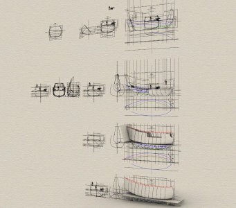
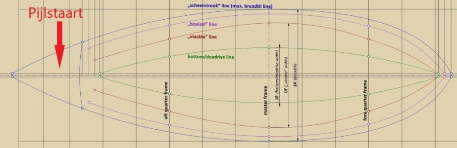
Be that as it may, work is moving forward (partly because it isn’t being slowed down by any conversion issues :)), and I’ve just finished shaping the underwater section of the hull. As can be seen in the attached graphic, I chose the shape of design lines in such a way as to achieve almost the maximum possible sharpness of both the entry and run, which seems essential for such a proportionally short hull (only 3:1!), so that the vessel isn’t horrendously sluggish and leewardly, and which distinguishes it in this regard as well from previous reconstruction attempts and replicas of the vessel.

005.jpg

006.jpg


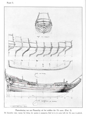
For context, pinnaces — which are, in a sense, the successors to vlieboots — feature equally sharp shapes, as can be seen in quasi-design sketches from some decades later. Particular attention should be paid here to the shape of the first (two) and last (two) frames:

pinasa holenderska XVII w.jpg

pinasschip of jacht van 70 x 19 x 9 voet - 1630 - A.0149 [nr 0021].jpg

pinasschip van 90 x 24 voet - 1650 - A.0149 [nr 0016].jpg
.​
 
Last edited:
.​
For these reasons, there can be no question of any “scale errors”, since no scaling is being performed.

I would also add that ship reconstructions can be — and indeed, in my specific case, are — created in digital space at actual size; that is, one basic unit of length in the virtual model corresponds to one basic unit of length taken from the source contract, which is not possible when drawing on paper or building a scale model. As you can see, there is absolutely no fuss about a specific foot dimension or the hassle of constantly scaling anything, which is precisely what generates errors.

.​
 
In a previous post I have mentioned what a privilege it is for me to experience the design process of "my" ship. I say "mine", because early on in my research I have started to develop a particular affinity for De Zwane. Whether it is because there is the most information available on her, or whether it is because she was by all accounts an excellent sailor, I don't know. But the truth is I am quite emotional as I am witnessing this ever-elusive build contract being transformed into the actual ship that was part of history. I am sure that the majority of modelers probably do not even spare a second thought thinking about how the plans and designs of the models they are building, came about, but to me it is something I will never take for granted.

And what makes this even more special is the fact I can peek over Waldemar's shoulder as history is brought to life. Call me emotional or sentimental or whatever you will - to me this is an incredibly special moment.
 
.​
Goodness me, Heinrich, thanks. I was planning to take a few days off, but after what you’ve written, I think I’ll abandon that wicked plan... :)

* * *​

Fine-tuning

However, geometric simulations of the initial reconstruction variant carried out at a later stage led me to decide to continue the search for a more convincing solution. And rightly so. The final result now appears entirely consistent in every possible way: internally, with the provisions of the contracts, with the surviving design drawings from that era, and whatever else. It is not, though, consistent with the explanations offered by today’s authors on this matter, which have also been applied in previous reconstructions of this kind.

Be that as it may, the diagram below illustrates the essence of the solution found for Barentsz’s vlieboot, based on data taken from the contracts for the construction of these vessels from the turn of the 16th and 17th centuries. Data taken directly from the contract records is shown in red; the rest, identified through graphical analysis, is shown in black.


007.jpg


First and foremost, the proposed update involves, in particular, a reduction in the overall height of the hull at midship (i.e. the master frame) by two feet. Despite this adjustment, the reconstruction essentially retains all the fundamental requirements for ships mentioned earlier in this thread, albeit with certain dimensional amendments, as follows:

the depth is reduced from 12 to 10 feet,
the maximum breadth above the waterline is reduced from 2 to 1 foot (which, hydrostatically, may still be acceptable for the resulting, quite full shape of the master frame, and especially for low-loaded cargo ships, i.e. those with a low centre of gravity),
the height of the gun ports is reduced from 4 feet 5 inches to merely 3 feet 5 inches, or approximately one metre (this is very little, yet according to the standards of the era it still falls within the permissible limits for cargo ships of moderate size, at least according to Edmund Bushnell’s explanations from 1660).

Incidentally, the height between decks was increased in the reconstruction from 6 feet to 6.5 feet, primarily to avoid excessive deck rise in the aft half of the ship, which would have made it too steep longitudinally and thus uncomfortable for the crew.

It is worth noting that some of the dimensions in the diagram are primary, whilst others are derived (which the diagram itself does not explain), so the order in which the individual design elements are determined in successive stages is crucial.

As regards the most important stages of shaping the master frame in procedural terms, first a conceptual deadrise point was determined with absolutely standard parameters known from sources (a few inches in height, here six inches, and a span of 2/3 of the hull’s breadth), followed by the lower point of the side height, i.e. at the ‘boeisel’ level (also of a conceptual nature), the latter shown but not described in the diagram, after which both these points were connected by a line. The intersection of this line with the individual diagonal of the master frame yields the ‘vlak’ point, the coordinates of which are already specified in some contracts for the construction of vlieboats from this period (2 feet and 19 feet respectively, which perfectly corresponds to the values obtained in this reconstruction in the manner described above).

.​
 
Last edited:
Back
Top