- Joined
- Jan 9, 2020
- Messages
- 10,566
- Points
- 938

Dear Friends
As promised earlier, I invite you all to join me in the build of the Kolderstok Batavia (hereafter the Haarlem as I will explain later). As this is my first build of such a high-end kit, I welcome all input, so please feel free to give as much advice and criticism as you possibly can.
I am not going to repeat my lengthy introduction of the kit and Kolderstok Models - the review is published in the Section: Kit Reviews: Wood, Plastic, Paper. (By the way, thank you all for the tremendous and positive response on that posting). Please see the following link:
Kolderstok has designed the Batavia model to a scale of 1:72 using the Lelystad replica - built by master shipwright, Willem Vos - as an example. Hull, rigging, decks, ornaments etc. are all based on the full-sized replica at the Batavia wharf. The kit contains laser-cut keel and frames, full (single) walnut planking, decks, masts and hand-cast ornaments. Sails are available as a separate kit, containing fabric, plans, instructions, extra thread, blocks and belaying pins. Also availabe is a rescue boat with a length of 12 cm.
Specifications and dimensions of the model are as follows:
Length: 95 cm / 37.4 inch (incl. Bowsprit)
Width: 35 cm / 13.8 inch (at main yard)
Height: 80 cm / 31.50 inch (incl.Standard)
Armament: 24 cannons: 22 shown (two closed gunports)
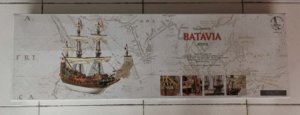
In all the cost of this beautifully presented kit (including all the accessories and shipment from the Netherlands to China) came to € 526. The only item that I did not order at this stage is the lifeboat.
BATAVIA HISTORY
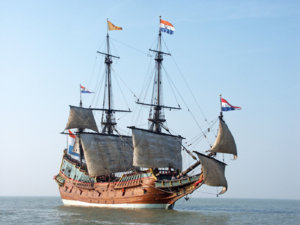
The Batavia was the flagship of the Dutch East India Company (VOC) and was listed as a Spiegelretourschip, also known as a Return Ship, or East Indiaman. These ships were used by the Dutch East India Company for return journeys between the Netherlands and the Dutch colonies. For transport duties, the Spiegelretourchip was the most important vessel to the V.O.C. - hence these were classified as “ship” as opposed to, for instance, “Jacht” or “Pinas” (Pinnace). In essence, these ships were the same as the battleships of the Dutch Republic and they were armed with the same type of armament - only the number of cannons was different. In case of emergency (e.g. the War against England) it was thus not uncommon that these ships were commandeered for use by the Admiralty.

This drawing of the Batavia is supplied courtesy of the Western Australian Maritime Museum. The marked section shows the salvaged part of the ship which is on display at the museum.
In 1614, the V.O.C. categorized the Spiegelretourschip into three classes or charters. The smallest class measured 130 feet (36,80m) in length; the medium-class 138 feet (39,05m), and the largest class 150 feet (42,45 m). In 1626, the VOC revised this classification to increase the maximum length to 160 feet (45,28 m). The only exception was the ships built by the Chamber of Zeeland which were allowed a maximum length of 170 feet (48,11m). Built in 1628 for the Chamber of Amsterdam by the East India Dockyard at the “Peperwerf” (Pepper Wharf - Amsterdam), the Batavia was built to conform to the VOC’s “New Classification” of 160 feet. The construction process took approximately 8 months to complete and was concluded at a cost of fl.100.000 gulden. The average life expectancy of a spiegelretourchip was penned at approximately fifteen years.
Note: One Amsterdam foot (Amsterdamse voet; 11 Amsterdam inches) was 28.3133 cm.
In addition to a big load capacity, East Indiamen were also capable of carrying passengers. They were three-masters, carrying square sails or a combination of square and staysails, while the sprit often had a course and topsail. These ships were characterised by the galleon, which could measure up to one fifth of the total length of the ship and from which the spritsails were controlled. To defend herself in combat and to protect her precious cargo, the ship carried 24 cannons.
Batavia Specifications:
Country of Origin: Dutch Republic
Name: Batavia, Dutch East Indies
Owner: Dutch East India Company
Completed: 1628
Maiden Voyage: 29 October 1628
On Board: 341 heads
Fate: Wrecked; 4 June 1629
Location: Wallabi Group, Houtman Abrolhos
General Characteristics
Class and Type: East Indiaman
Tonnage: 650 “Last” (Dutch measurement for tonnage)
Displacement: 1 200 tons
Length: 160 ft (53 m)
Beam: 36 ft (11 m)
Height: 180 ft (55 m)
Draught: 17 ft (5.1m)
Sail Plan: Fully rigged ship
Sail Area: 33 000 sq. ft (1 100 sq. m)
Speed: 5 knots (9.3 km/h; 5.8 mph)
Armament: 24 x Cast-Iron cannons
The Batavia gained her fame - or notoriety - for being shipwrecked off the Australian coast on her maiden voyage in 1628/29 to the Dutch East Indies (Indonesia) and the report written by captain Francisco Pelsaert: Unfortunate Voyage of the ship Batavia. Remains of the ship and of the cruelties committed after her wrecking can be viewed at the western Australian Museum in Fremantle, Australia. There is a tremendous amount of information available on the internet as to what gave rise to the mutiny and the gruesome deeds that were committed subsequently, so if you want to find out more, simply Google: Batavia Ship 1628.
THE V.O.C. SHIP HAARLEM (Also known as the “Ship that Shaped South Africa’s future").
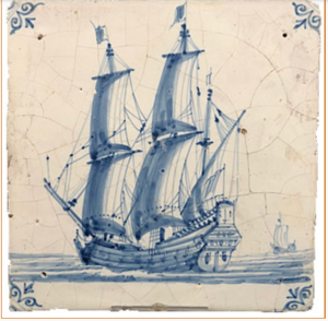
This tile, courtesy of the M. van Halderen Collection, depicts the Haarlem. The sword that appears as decoration on the stern (Spiegel) of the ship, shows the sword which forms part of the shield which, in turn, is part of the coat of arms of the city of Haarlem.
Despite all the credentials of the Batavia, I have elected not to build her per se, but a variation thereof. I prefer to call it a variation, because the only two visual differences amount to the stern ornamentation and the number of cannons so “kit bashing” it ain’t! Interestingly, the Haarlem’s tonnage is listed at 250 “Last” or 500 tons unlike the Batavia’s 650 “Last” or 1 200 tons. The reason for this is unclear to me at this stage. Like the Batavia, the Haarlem was a Spiegelretourchip, built at the same shipyard and by the same master shipwright - 8 years later in 1636.
So why the Haarlem? Whereas the Batavia’s fate was linked to Australian history, so was the Haarlem’s fate linked to the Cape of Good Hope that would later develop into South Africa. The choice of the Haarlem to a South African with Dutch origins (me !), was thus a no-brainer.
The Haarlem - carrying a cargo of Chinese porcelain, guinee cloth, black pepper and cinnamon - ran aground close to the eastern shore of Table Bay, near present day Cape Town, on 25 March 1647. Soon after, a group of about 58 of the crew were taken aboard other ships and returned to the Dutch Republic. The remaining 62 survivors stayed behind to salvage as much as possible from the wreck. During a period of about a year they lived in a camp close to the shipwreck, on strange ground in Terra Incognita.
One of the people in charge of the salvage operation, Junior Merchant Leendert Jansz, recorded the events at the time in a journal which formed the basis for another document, the Remonstrantie, which led to a decision by the VOC to establish a refreshment station for passing ships at the Cape. The wrecking of the Haarlem resulted in the arrival, in 1652, of Jan van Riebeeck, under whose leadership the first permanent European settlement in these parts was established. This settlement later developed into the City of Cape Town and lay at the basis of present-day South Africa.
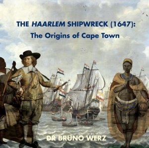
The author of this book, Dutch archaeologist Dr Bruno Werz, has devoted the last 31 years of his life to finding the shipwreck of the Haarlem near Bloubergstrand, Cape Town. Last year in September it was announced that Werz had in all likelihood (95% surety) located the exact position of the wreck. Fundraising efforts are on the way at the moment for the salvaging of the shipwreck. (More on this, and the findings of Dr Werz will be discussed in detail later).
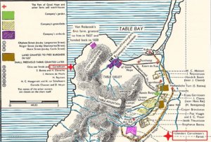
But there’s more: When Van Riebeeck set foot on land on 6 April 1652, among his company of 82 men and 8 women were three men (that I know of) who bore the surname “Cornelissen” (my surname). They are well documented in Van Riebeeck’s journal as they were among the first Free Burghers / Free Citizens. Permits were issued in February 1657 to nine company servants (who became the first Free Burghers) to farm their own land in order to relieve the wheat shortage. Among them were Peter Cornelissen, who had been an expert hunter in the V.OC.’s service, Jan Cornelissen a farmer by trade and Leendert Cornelissen - a ships carpenter, who received a strip of forest to cut timber for the settlement.
The map below shows the farms allocated to the first of these men.
This then concludes the first part of my post. The next step will deal with the actual building log of the model.
Thank you all for your interest and for reading.
Kind regards, Heinrich
As promised earlier, I invite you all to join me in the build of the Kolderstok Batavia (hereafter the Haarlem as I will explain later). As this is my first build of such a high-end kit, I welcome all input, so please feel free to give as much advice and criticism as you possibly can.
I am not going to repeat my lengthy introduction of the kit and Kolderstok Models - the review is published in the Section: Kit Reviews: Wood, Plastic, Paper. (By the way, thank you all for the tremendous and positive response on that posting). Please see the following link:
Kit Review - BATAVIA - KOLDERSTOK
Dear Friends I have been asked by Maarten and Uwe to submit a kit review on my newly acquired Kolderstok model of the Batavia VOC Spiegelretourschip. This is I do with pleasure. On Tuesday 28 January, I ordered the VOC Retourschip (Return Ship), Batavia from Hans Nieuwkoop - the founder and...
shipsofscale.com
Kolderstok has designed the Batavia model to a scale of 1:72 using the Lelystad replica - built by master shipwright, Willem Vos - as an example. Hull, rigging, decks, ornaments etc. are all based on the full-sized replica at the Batavia wharf. The kit contains laser-cut keel and frames, full (single) walnut planking, decks, masts and hand-cast ornaments. Sails are available as a separate kit, containing fabric, plans, instructions, extra thread, blocks and belaying pins. Also availabe is a rescue boat with a length of 12 cm.
Specifications and dimensions of the model are as follows:
Length: 95 cm / 37.4 inch (incl. Bowsprit)
Width: 35 cm / 13.8 inch (at main yard)
Height: 80 cm / 31.50 inch (incl.Standard)
Armament: 24 cannons: 22 shown (two closed gunports)

In all the cost of this beautifully presented kit (including all the accessories and shipment from the Netherlands to China) came to € 526. The only item that I did not order at this stage is the lifeboat.
BATAVIA HISTORY

The Batavia was the flagship of the Dutch East India Company (VOC) and was listed as a Spiegelretourschip, also known as a Return Ship, or East Indiaman. These ships were used by the Dutch East India Company for return journeys between the Netherlands and the Dutch colonies. For transport duties, the Spiegelretourchip was the most important vessel to the V.O.C. - hence these were classified as “ship” as opposed to, for instance, “Jacht” or “Pinas” (Pinnace). In essence, these ships were the same as the battleships of the Dutch Republic and they were armed with the same type of armament - only the number of cannons was different. In case of emergency (e.g. the War against England) it was thus not uncommon that these ships were commandeered for use by the Admiralty.

This drawing of the Batavia is supplied courtesy of the Western Australian Maritime Museum. The marked section shows the salvaged part of the ship which is on display at the museum.
In 1614, the V.O.C. categorized the Spiegelretourschip into three classes or charters. The smallest class measured 130 feet (36,80m) in length; the medium-class 138 feet (39,05m), and the largest class 150 feet (42,45 m). In 1626, the VOC revised this classification to increase the maximum length to 160 feet (45,28 m). The only exception was the ships built by the Chamber of Zeeland which were allowed a maximum length of 170 feet (48,11m). Built in 1628 for the Chamber of Amsterdam by the East India Dockyard at the “Peperwerf” (Pepper Wharf - Amsterdam), the Batavia was built to conform to the VOC’s “New Classification” of 160 feet. The construction process took approximately 8 months to complete and was concluded at a cost of fl.100.000 gulden. The average life expectancy of a spiegelretourchip was penned at approximately fifteen years.
Note: One Amsterdam foot (Amsterdamse voet; 11 Amsterdam inches) was 28.3133 cm.
In addition to a big load capacity, East Indiamen were also capable of carrying passengers. They were three-masters, carrying square sails or a combination of square and staysails, while the sprit often had a course and topsail. These ships were characterised by the galleon, which could measure up to one fifth of the total length of the ship and from which the spritsails were controlled. To defend herself in combat and to protect her precious cargo, the ship carried 24 cannons.
Batavia Specifications:
Country of Origin: Dutch Republic
Name: Batavia, Dutch East Indies
Owner: Dutch East India Company
Completed: 1628
Maiden Voyage: 29 October 1628
On Board: 341 heads
Fate: Wrecked; 4 June 1629
Location: Wallabi Group, Houtman Abrolhos
General Characteristics
Class and Type: East Indiaman
Tonnage: 650 “Last” (Dutch measurement for tonnage)
Displacement: 1 200 tons
Length: 160 ft (53 m)
Beam: 36 ft (11 m)
Height: 180 ft (55 m)
Draught: 17 ft (5.1m)
Sail Plan: Fully rigged ship
Sail Area: 33 000 sq. ft (1 100 sq. m)
Speed: 5 knots (9.3 km/h; 5.8 mph)
Armament: 24 x Cast-Iron cannons
The Batavia gained her fame - or notoriety - for being shipwrecked off the Australian coast on her maiden voyage in 1628/29 to the Dutch East Indies (Indonesia) and the report written by captain Francisco Pelsaert: Unfortunate Voyage of the ship Batavia. Remains of the ship and of the cruelties committed after her wrecking can be viewed at the western Australian Museum in Fremantle, Australia. There is a tremendous amount of information available on the internet as to what gave rise to the mutiny and the gruesome deeds that were committed subsequently, so if you want to find out more, simply Google: Batavia Ship 1628.
THE V.O.C. SHIP HAARLEM (Also known as the “Ship that Shaped South Africa’s future").

This tile, courtesy of the M. van Halderen Collection, depicts the Haarlem. The sword that appears as decoration on the stern (Spiegel) of the ship, shows the sword which forms part of the shield which, in turn, is part of the coat of arms of the city of Haarlem.
Despite all the credentials of the Batavia, I have elected not to build her per se, but a variation thereof. I prefer to call it a variation, because the only two visual differences amount to the stern ornamentation and the number of cannons so “kit bashing” it ain’t! Interestingly, the Haarlem’s tonnage is listed at 250 “Last” or 500 tons unlike the Batavia’s 650 “Last” or 1 200 tons. The reason for this is unclear to me at this stage. Like the Batavia, the Haarlem was a Spiegelretourchip, built at the same shipyard and by the same master shipwright - 8 years later in 1636.
So why the Haarlem? Whereas the Batavia’s fate was linked to Australian history, so was the Haarlem’s fate linked to the Cape of Good Hope that would later develop into South Africa. The choice of the Haarlem to a South African with Dutch origins (me !), was thus a no-brainer.
The Haarlem - carrying a cargo of Chinese porcelain, guinee cloth, black pepper and cinnamon - ran aground close to the eastern shore of Table Bay, near present day Cape Town, on 25 March 1647. Soon after, a group of about 58 of the crew were taken aboard other ships and returned to the Dutch Republic. The remaining 62 survivors stayed behind to salvage as much as possible from the wreck. During a period of about a year they lived in a camp close to the shipwreck, on strange ground in Terra Incognita.
One of the people in charge of the salvage operation, Junior Merchant Leendert Jansz, recorded the events at the time in a journal which formed the basis for another document, the Remonstrantie, which led to a decision by the VOC to establish a refreshment station for passing ships at the Cape. The wrecking of the Haarlem resulted in the arrival, in 1652, of Jan van Riebeeck, under whose leadership the first permanent European settlement in these parts was established. This settlement later developed into the City of Cape Town and lay at the basis of present-day South Africa.

The author of this book, Dutch archaeologist Dr Bruno Werz, has devoted the last 31 years of his life to finding the shipwreck of the Haarlem near Bloubergstrand, Cape Town. Last year in September it was announced that Werz had in all likelihood (95% surety) located the exact position of the wreck. Fundraising efforts are on the way at the moment for the salvaging of the shipwreck. (More on this, and the findings of Dr Werz will be discussed in detail later).
But there’s more: When Van Riebeeck set foot on land on 6 April 1652, among his company of 82 men and 8 women were three men (that I know of) who bore the surname “Cornelissen” (my surname). They are well documented in Van Riebeeck’s journal as they were among the first Free Burghers / Free Citizens. Permits were issued in February 1657 to nine company servants (who became the first Free Burghers) to farm their own land in order to relieve the wheat shortage. Among them were Peter Cornelissen, who had been an expert hunter in the V.OC.’s service, Jan Cornelissen a farmer by trade and Leendert Cornelissen - a ships carpenter, who received a strip of forest to cut timber for the settlement.
The map below shows the farms allocated to the first of these men.

This then concludes the first part of my post. The next step will deal with the actual building log of the model.
Thank you all for your interest and for reading.
Kind regards, Heinrich


