Who knows about wiring LED lights into a model?

Joined
Dec 15, 2019
Messages
99
Points
143

I'm posting this here as there appears to be no forum specifically for electrical things.

. . . and speaking of electrical things, the following questions will reveal my serious lack of knowledge of things electrical and electronic.

I'm considering doing a cross section and in all of the 'in my head' planning of the project I have given consideration to having lanterns inside the decks.
I understand that LED lights are the way to go -- they seem to give a good bright light with virtually no heat.

I'm thinking that LEDs rated around 3 volts would probably be suitable for inside a cross section?

I would expect to be fitting 6 - 8 LEDs in the form of hanging lanterns but Google has shown me some conflicting information as to how to wire multiple lights.

Is it feasible to have the wires for all these lights 'running around' inside the ship [in series?] but only having two wires ( a + and a - ) coming into the ship from a battery or other power source? - - - or would all lights require their wires to be led out of the ship back to battery/power source? (For 8 lights that would be 16 wires -- OOOOH! )

Some info I have read says the lights can be just wired straight from a battery via an on/off switch, while other info says a resistor needs to be fitted for each light ???

I'm confused !!!

OK ~ I'll leave the questions there for now, but there may be more in my quest to understand this stuff!
 
This should be a good start:

-------------------------------------------------------------------------------------------------------------------------------------
/ \ \ \ \ \ \ \
9V battery 470ohm 470ohm 470ohm 470ohm 470ohm 470ohm 470ohm
LED LED LED LED LED LED LED
\ / / / / / / /
---------------------------------------------------------------------------------------------------------------------------------------

Remember, the LEDs are directional, so hook up the first one to the battery (through the resistor) to see if it lights or not. Then hook the rest of the LEDs up the same way. There will be a mark or a longer lead or something identifying a direction on the LED. If it is too bright use more resistance to cut it back (try 1kohm) and if too dim use less resistance (270 ohms). Touch the resistor to make sure they aren't getting hot if you want it really bright (they shouldn't be). They don't all have to be the same brightness either, use a different resistor on each one if you like.
 
Last edited:
Hello maywiyj,
Thanks for your reply. Pity your diagram didn't display.

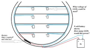
I've been looking at series wiring and wondered if the arrangement shown below would work?
If not, what modifications would I have to make?

LEDs.jpg
 
I would just send evan designs an e-mail, see the link below. I'm sure they can tell you what you need. The reason there is so much confusion is it depends on the leds your using and the look your going for. You can probably do it with a 3volt setup. Definitely in parallel. Maybe in series, though you might need more voltage in series. The brightness is controlled by the resister and typically having the led on max is too bright to look real. Evan design sells led chains but I don't know if the light spacing will work. As far as the number of wires, if you're using magnet wire, the wire is so fine it shouldn't be an issue. You can cut a cannel in the frame under the planks and run all the wires up that channel. Magnet wire is about the thickness of hair. It's hard to work with, and that's why going with a commercial product is probably better. If you're not really good with a soldering iron attaching a surface mount led to magnet wire can be quite a challenge.

Evan Designs
 
Thanks MystRacing and Jay for your comments and suggestion.

I've clicked the link and I think I see pretty much what I may need. I'm going to email them with a couple of questions so that I'll know I'm getting the right stuff and also know what to do with it!
 
I'm posting this here as there appears to be no forum specifically for electrical things.

. . . and speaking of electrical things, the following questions will reveal my serious lack of knowledge of things electrical and electronic.

I'm considering doing a cross section and in all of the 'in my head' planning of the project I have given consideration to having lanterns inside the decks.
I understand that LED lights are the way to go -- they seem to give a good bright light with virtually no heat.

I'm thinking that LEDs rated around 3 volts would probably be suitable for inside a cross section?

I would expect to be fitting 6 - 8 LEDs in the form of hanging lanterns but Google has shown me some conflicting information as to how to wire multiple lights.

Is it feasible to have the wires for all these lights 'running around' inside the ship [in series?] but only having two wires ( a + and a - ) coming into the ship from a battery or other power source? - - - or would all lights require their wires to be led out of the ship back to battery/power source? (For 8 lights that would be 16 wires -- OOOOH! )

Some info I have read says the lights can be just wired straight from a battery via an on/off switch, while other info says a resistor needs to be fitted for each light ???

I'm confused !!!

OK ~ I'll leave the questions there for now, but there may be more in my quest to understand this stuff!
I've been working on several 18th century tury ship models but took a break to make a diorama of an old winery from plaster of paris walls & old Lincoln logs for beams for my daughter. I installed grain-of-wheat bulbs wired to external doll house DC power supply. They were mounted to walls as sconces & a chandelier from the ceiling. She can plug it in when she wants to display such as when she has company. I wired in parallel so all bulbs had same brightness.
 
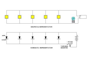
So, the diagram you have, the LED's are in "Series". I would not be so concerned about the voltage of the LED as most are all about the same. With the 9V battery, I would put attention to the single Resistor you have and that could be anywhere from 470 Ohms to 5000 ohms. Personally, instead of a FIXED resistor, I would buy a variable resistor (with the three legs) This way, you can vary the amount of current throughout the entire LED series. The reason is that you can adjust the variable resistor until you get the lighting that you want.
Next. I would buy from Evans Designs and consider the YELLOW LED's and not the white kind. The YELLOW LED's gives off a nice yellowish incandescent candle-like appearance. Lastly, if your LED's are going to be mounted INSIDE a later fixture, then I could go with the PICO sized LED's. Those little 1mm sized LED's can pack a punch.
I am not sure why you chose the "Series" method, I personally would go with a Parallel arrangement. Better control of the lighting.
Below is a parallel arrangement.

Drawing1.jpg
 
I would recommend Evan Designs as well. ( https://evandesigns.com/ ) They also have some video tutorials and can give you all the information you need. I did a similar project recently and I got the smallest LEDs they provided at the time (chip) and they now have even smaller ones (pico). They come in different colours and the yellow ones are a nice imitation of lantern light in my opinion. There is a limit to how many lights you can put on a circuit for the power supply (e.g. 3 or 9 volts) but that wasn't a factor--it's a high number. The answer to your questions is yes, you can wire all the lights together and run two wires out of the ship to the power source.

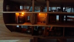
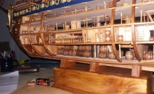
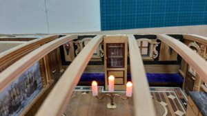
Here is a pic of my project (Soleil Royal in progress). I put the lights in the ceiling just to provide illumination not to make them look like lanterns. I gathered up all the wires and ran them through the pump pipes which you can see in the second picture. The wires lead into the base which is hollow and you can see the power supply (2 AAA batteries) which can be concealed in the base.

Hope this helps! Good luck6.jpg2.jpg
 
One other thing--some of these small LEDs have inline resistors so you can use the approach Donnie recommends--it would be much cleaner and simpler.
 
Thanks to sturb1ric, Donnie and Thomas or your comments.

Donnie, I haven't actually chosen the series circuit ~ I just used that on the forum so that I might get some helpful comments and whether that, or a parallel circuit would be best suited.
Since my previous post above I've been on the Evans Design website and there are plenty helpful videos there. I'm particularly leaning towards the parallel 3v circuit using the 3v pico LEDs shown in one of their videos. I vote heavily for the least complicated electrical system! . . . and that one looks like it would suit my just fine. I notice that they don't use any resistor(s) in that circuit and it says that up to 10 lights can be powered from the one 3 volt battery.

Thomas, that project of yours looks great! I'd be happy if mine materialises and looks half as good as that!
 
Hi Doc,

If you use a 9 volt battery you can put 3 x 3V leds in series. If you want to use this 9 volt battery the you have to use every time 3 x 3v leds in series and put these in parallel with more 3 x 3v leds to add more leds or use a resistor. Use the formula U=IxR to calculate. U= voltage, I is current in amps, R = resistance in Ohm.

As everybody said I would go for parallel and use a 3V battery. For these I use simple christmas leds, these are already wired in parallel and I just cut them to the amount I need and re wire them. The battery box with correct ressistor is also included.
I also switch flickering candle leds in parallel to these, see below.
20200125_182338.jpg
Keep in mind different color leds can request different voltages to work, if they get insufficient voltage they won t lid up.
 
Thanks Maarten for your comments and advice.

For the sake of simplicity, I'm pretty much settled on going for the 3v parallel circuit using 3v yellow pico LEDs.
I've seen these on other model builds and that's the result I'm hoping for.
 
Back
Top