Wright Flyer - Model Airways - 1:16 [COMPLETED BUILD]

Joined
Aug 1, 2020
Messages
727
Points
298

20211224

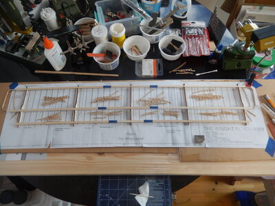
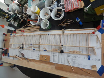
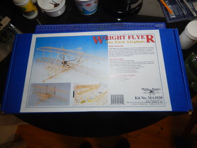
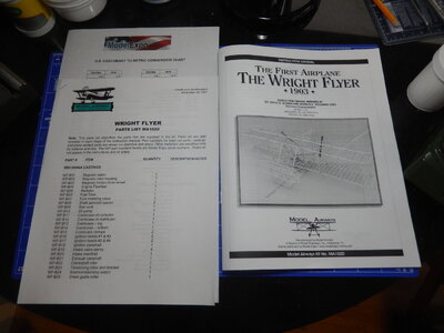
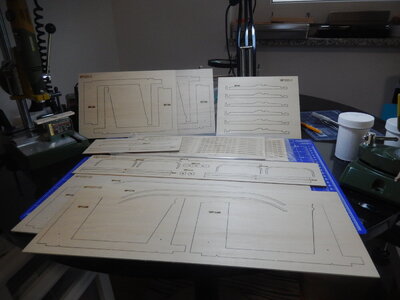
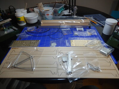
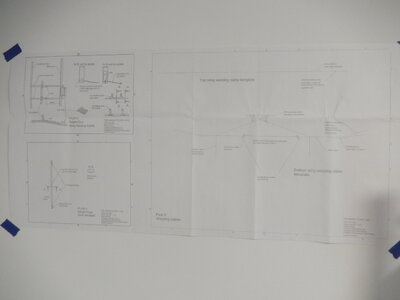
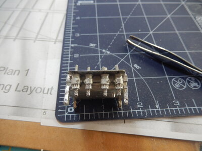
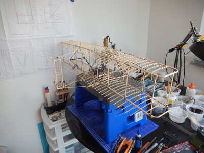
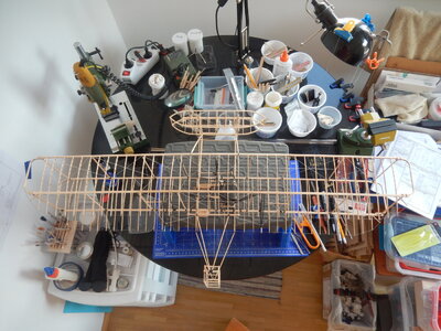
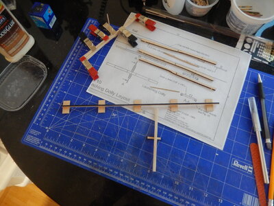
Started the Wright Flyer today by opening the box, reviewing the contents, reviewing the build log I found on the site, making a photo copy of the plans and a first look at the instruction book. First observation is that this is going to be a pretty big model (approx. 15-in by 30-in) meaning my normal modeling table (which is 90-cm round) is going to be barely big enough. Some additions (a wooden board and a large piece of cardboard) are going to be required to accommodate laying out the wings; acquiring the board will need to wait until Monday (after the Christmas weekend). In the mean time I will read over the instructions in detail and see if there is anything I can start assembling such as the engine.

DSCN8308.JPGDSCN8309.JPGDSCN8310.JPGDSCN8311.JPGDSCN8305.JPGDSCN8306.JPGDSCN8307.JPG
 
20211228

After reading over the instructions, and making quite a few edits, I decided that the instructions could stand a complete re-write. The errata provided at the end of the parts listing is just the beginning; plenty more were discovered as I worked to assemble the engine. I’m sure I’ll come across more as I assemble the wings and fuselage.

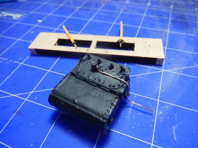
So much for the bashing. I actually had fun assembling the engine and magneto. I decided to start with these on Sunday while I waited until Monday when the hardware store was open and I could get the board needed to extend my work table.

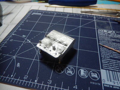
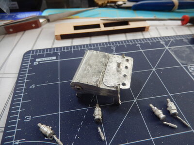
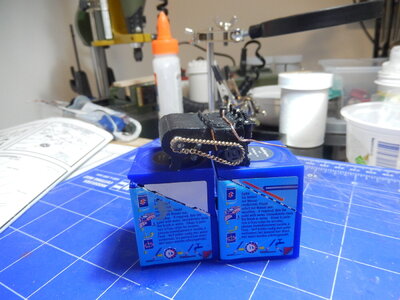
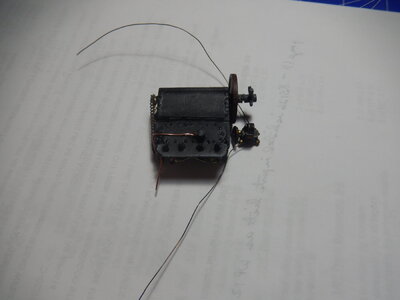
Compared to the Clerget 9B engine I built early this past year this engine is small. Working on parts of it was both interesting and a bit frustrating as my big, clumsy fingers got in the way. Working with the small brass parts was a challenge, especially the ignition strap, the gears and the chain. I had to give up trying to assemble the chain by reattaching links; finally resorted to gluing it in place and then tying the ends together with some thin thread. I will probably have to reroute the fuel line; will figure that out later on. The drive gears that go on the crankshaft just after the flywheel, along with the spacers, had holes that needed to be reamed out – a pain-in-the-neck operation at this scale with the round needle file I had (I have a standard size round needle file; could have used a smaller one).

The instructions mention a photo of the engine; there isn’t one in the instructions. Thankfully one of the other build logs had a picture. This came in handy as I was working out where some of the parts should fit. Based on the photo, I decided to paint the majority of the engine a flat black; I used this color for the magneto as well. The gears and chain were pained a gunmetal gray for contrast. I also pained the bearing surfaces of the engine flywheel and magneto drive wheel leather brown. The winding coils on the magneto were painted bronze (no copper paint in my stock so bronze it was).

I will put this on hold for a few days while I work on the 2 ROKR kits my grandkids sent me for Christmas. One is a solar array electric rover; the other is a working clock.

DSCN8317.JPGDSCN8320.JPGDSCN8321.JPGDSCN8322.JPGDSCN8326.JPGDSCN8329.JPGDSCN8331.JPGDSCN8333.JPGDSCN8334.JPGDSCN8335.JPGDSCN8336.JPGDSCN8337.JPG
 
I will be following your build to see how it goes, so please let us know what issues you come across.

Having been an aircraft mechanic for dozens of years in the military, I am interested in this kit.

I have built many of the smaller Guillows kits many years ago and like the open frame style of these kits.
 
Will follow you with pleasure also

I did the Sopwith Camel a few year back it was real fun to do:cool:
 
20220101

Happy New Year!

Finished the 2 ROKR puzzles this past week so on New Year’s eve it was back to the Wright Flyer. Yesterday and today were about assembling the upper wing.

First, as has been mentioned by others, there are lots of small wooden (and metal) parts and most of the wooden ones are fragile. Go slow, take it easy, take your time, patience is a virtue, etc. I had no problem following all of that advice with the thin rib material; my mistake came with one of the wing tips. While sanding the inside curve on one of the tips I either pressed a bit too hard or torqued the material a bit – 1 large, 1 small & 1 in-between pieces of material. Take a breath, get up and walk around, return to the work table. A little bit of CA later and the wingtip was repaired so it is difficult to see where the break occurred (chose to go the repair route rather than reach out to Model Expo for replacements; would take a bit too long to receive them). To avoid any more issues with sanding the repaired wingtip and the other wingtip I decided to use the sanding drum in my Proxxon drill – and a light touch. No further problems.

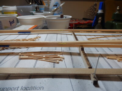
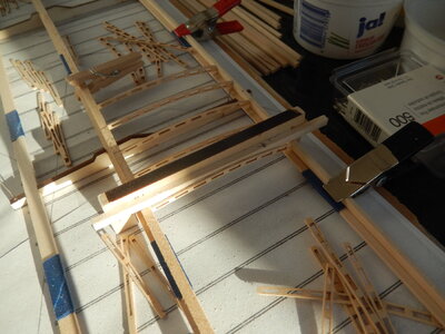
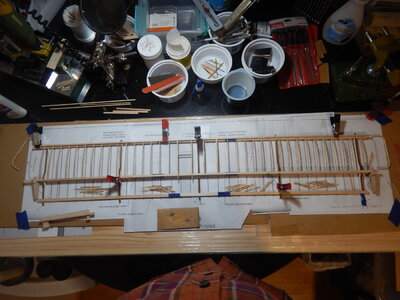
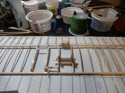
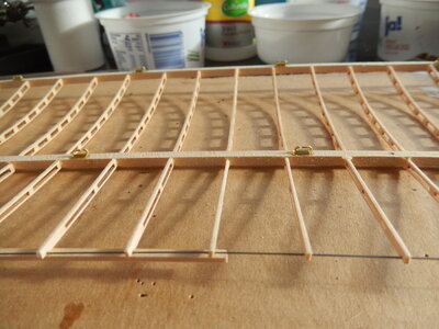
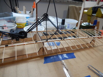
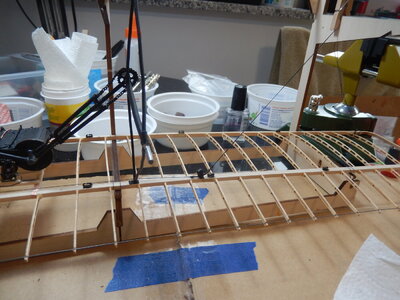
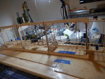
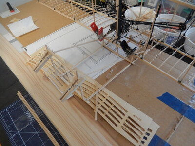
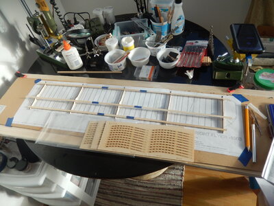
Sanding all of the wind ribs for the upper wing and assembling the wing spars was yesterday’s task. Gluing the ribs to the spars, adding the wing tips and adding the trailing edge wire was today’s task. Upper wing is now complete.

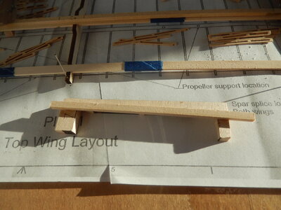
To help line up the forward ribs I cut some scrap wood to form a ‘square’. It fits over the forward and main spars, rests on the work surface and has a bearing surface to assist with keeping the ribs square and plumb. The aft ribs were installed by lining them up with the forward ribs by eyeball. (Watch the QC. When I was installing the trailing edge wire, I found two aft ribs that I’d installed upside down. Removed and reinstalled them properly.)

The wing tips are reinforced at the spars by 2 wraps of cord. I used 0.25mm tan rigging thread left over from a ship model. I sealed the knots and darkened the thread with clear nail polish.

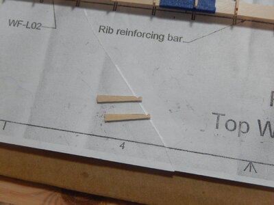
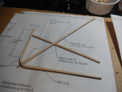
One item to be aware of is the outboard diagonal brace struts behind the wing tips at the trailing edge of the wings. The instructions say to cut them from 1mm x 3mm stock and make them 20 mm long. First, don’t go looking for any 1mm x 3mm stock in the kit; there isn’t any. These need to be cut from the scrap that is left after removing the ribs from one of the sheets. Second, check the plans. A 20mm length was too short for the diagonal brace struts that I needed. 22mm worked perfectly.

There is a rib reinforcing bar that goes on the top of the upper wing, at the trailing edge and centered. The instructions state ‘as shown’; the plans are drawn so this reinforcement appears to be on the underside of the upper wing. Don’t spend any time looking for a photo or sketch in the instructions. Take a look at the photo on the box cover and you can see how the reinforcement is installed.

I used yellow Elmer’s glue (carpenter’s glue) to assemble the ribs to the wing spars. I used the same glue when I started to attach the trailing edge wire to the aft rib sections; switched to CA after I’d done about ½ of the right-hand trailing edge wire.

After looking at some other build logs I thought about staining the wings and fuselage structure. I’ve decided not to stain the wood but to seal the wings and fuselage structures with something close to clear; probably a shellac or varnish (all depends what I can find in the local building goods store next week).

I’ll start on the bottom wing tomorrow.
DSCN8338.JPGDSCN8339.JPGDSCN8341.JPGDSCN8343.JPGDSCN8344.JPGDSCN8346.JPGDSCN8348.JPGDSCN8349.JPGDSCN8350.JPGDSCN8351.JPGDSCN8353.JPGDSCN8354.JPGDSCN8356.JPGDSCN8357.JPGDSCN8360.JPGDSCN8361.JPG
 
20220109

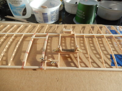
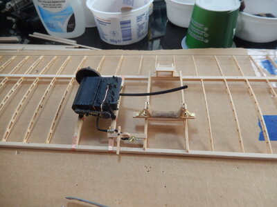
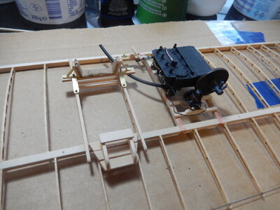
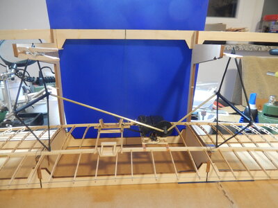
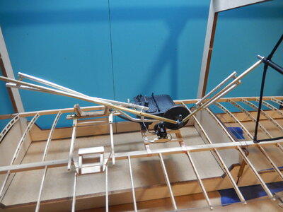
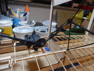
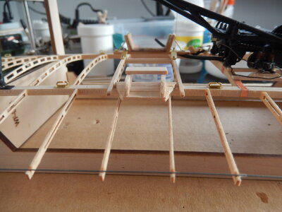
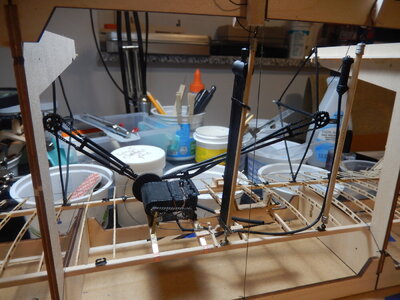
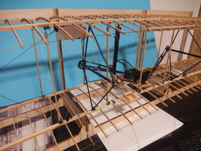
This past week was all about getting the bottom wing constructed – to include mounting the motor & magneto and making engine control connections.

While working on the bottom wing, I decided to listen to David McCullough’s book ‘The Wright Brothers’. I find it fascinating their determination to succeed with becoming capable of powered flight and the doggedness that they brought to solving all of the myriad issues along the way – determining the best airfoil shape for their wings, rudder and elevator; coordinating wing warping and rudders for coordinated turns; building their own engines; devising a means to launch planes so that the low power engines of the day could then keep them aloft; etc. It is really amazing how quickly aviation took off – not from 1903 but from the 1908 US and European demonstrations to the advanced planes just 10 years later at the end of WW I. I can see myself eventually building the Sopwith Camel….

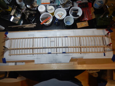
The lower wing gave me a bit more aggravation fitting the ribs; had to remove a couple an reinstall them. There are several extra forward ribs (the long ones between the leading edge of the wing and the main spar) but there are only 3 extra rear ribs (and I needed to use all 3 as 2 of the rear ribs had small cracks in them and I broke one during sanding). Patience, the occasional muttered mild curse and some laughter (followed by starting something over) helped me get to the end point – bottom wing ready to receive the engine.

For finishing, I decided to go with a couple of coats of clear, matte finish, lacquer (from a spray can). I like the look of the wood and the finish will help keep it looking nice. No further discussion needed.

The tubing for the gas and radiator lines is a bit of a pain to work with. It is thin walled and kinks like crazy when forced to bend or curve. I’ve tried the suggested ‘put some wire inside where it bends/curves’ but that doesn’t really prevent the plastic tubing from flattening out at the bends/curves. I’ve decided that the tubing that shows (the remaining gas and radiator lines that I haven’t worked on yet) will get enough attention to prevent the flattening (perhaps 2 pieces of the thin wire that came with the kit or a larger diameter wire will work). As for the lower radiator hose on the engine and the 2 small gas lines already installed, they are mostly concealed behind framing and wires so I’ve decided to leave them ‘as is’.

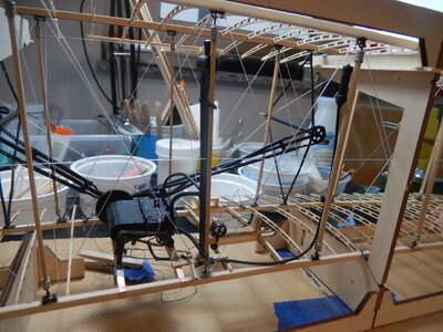
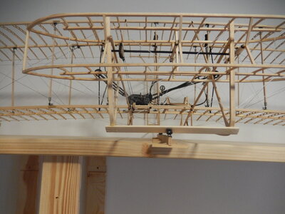
I simulated the hardware connecting the engine control lever to the radiator support and the wing warping cradle to the pilot’s support frame by using cut-down lengths of straight pins and inserting them into small holes drilled in the framework. After gluing them in, the tops were painted black to simulate bolts.

For the wires connecting the speed control hardware to the engine control lever black thread (left over from one of the ship models) was used. This was inserted through forward & aft holes drilled in the control lever and then knotted underneath; the thread was then glued to the top of the speed control cam. The directions called for thread painted brass to be used to simulate a control rod running from the aft end of the control lever to the gas cock valve handle. Not having any brass-colored paint, a small section of copper wire glued between the two points was used to simulate the control rod.

This next week I will be working on assembling the upper and lower wings together – installing struts, the wing warping mechanism, rigging, etc.

DSCN8362.JPGDSCN8363.JPGDSCN8365.JPGDSCN8367.JPGDSCN8368.JPGDSCN8370.JPGDSCN8371.JPGDSCN8373.JPGDSCN8375.JPGDSCN8377.JPGDSCN8378.JPGDSCN8379.JPGDSCN8381.JPGDSCN8383.JPG
 
on fuel lines.... I have seen photos of models with radial engines that the modeller simply used copper or brass wire fo the correct diameter and bent that. Also the use of plastic rod is a standard trick.

But it is a nice build overall.
 
20220118

Not a lot of visible progress this past week – but a lot of work put in. Worked on the propeller chain drive system which meant my fat fingers were involved with attaching small pieces of chain around gears in hard to work in places. Between cutting, gluing and painting metal (britannia and brass) to look like steel and bicycle chains; then assembling everything to the business end of the motor (to aft end with the small drive sprockets); and then gluing the drive chains in place it was a busy time. Often I had to put the tools and glue away and take a step back to – to both wait for epoxy to setup and to clear my head.

Just when I finished the drive chain assembly it was on to more little metallic bits (which I still need to paint black): the strut brackets on both wings. Gluing the bases to the top of the bottom wing and the bottom of the top wing on both the leading edge and main spars was simple (CA and tweezers). Gluing the actual attachment part of the brackets to the bases took time (epoxy, wait to set a bit, install the part, gently hold it in the upright position with a couple of toothpicks, move the toothpicks, make any needed final adjustment, do the same for the next part, walk away for a bit and then start over). I could get 2 to 3 of the parts glued into place before I needed to mix up a new small batch of epoxy. Definitely some wastage but not too bad overall.

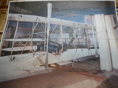
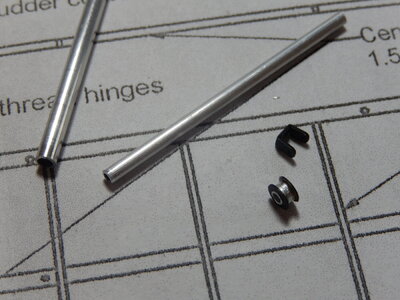
Four more little metal parts (wing warping pulleys; made of brass and aluminum tubing [to simulate the actual pulleys]) were still needed but I put them on hold for the better part of a day while I did some research. As with a few other parts of the instructions, the section on the wing warping system is a bit unclear at times; even after reading them over several times. The section of the plans and the figures that cover this system can also leave one scratching their head. Some research was definitely in order. Since I couldn’t visit the Smithsonian Air & Space Museum (which I would have liked to do!) it was time to get on the internet and do some surfing. The section on the Smithsonian’s website about the Wright Flyer is wonderful place to get pictures from (a section of one is attached). These helped me get it clear in my head how the wing warping wires are attached to everything. Of course, like most forays onto the web, additional looking turned up lots of other pictures of the Wright’s and their early flyers; really nice that these have been preserved. [No apologies for the lengthy post; as a licensed pilot, all things related to the early planes is definitely of interest.]

Last of the little metal bits are now attached to the wings. After they get a coat of paint so they look like the steel they are supposed to be, it will be on to the initial installation of the wing warping wires and then on to making the struts. And more little bits in other places....

[Smithsonian Wright Flyer webpage: https://airandspace.si.edu/stories/editorial/real-wright-flyer . For the collection of photos, click on 1903 Wright Flyer on the right hand side.]

DSCN8385.JPGDSCN8387.JPGDSCN8390.JPGDSCN8391.JPGDSCN8393.JPGDSCN8394.JPGDSCN8396.JPGDSCN8397.JPG
 
20220123

May not seem like much occurred this week but the painting of the strut supports and wing warping pulley housings is now complete and the wing warping wires are installed on the bottom & top wings. I couldn’t tell from the photos how the RH wing warping wire is actually connected to the wing warping cradle (inboard or outboard of the propeller mount); I installed it inboard because the engine block is in the way of connecting it outboard (unless the wire is run under the engine). From the photos the LH wire is attached from the cradle outboard of the propeller mount. (Some day I’ll pay a visit to the Smithsonian and if the RH side wire needs to be reattached outboard of the propeller mount, I’ll make the correction.) I used black rigging thread for the wing warping wires to make them easier to see on the finished model (a deviation from trying to keep as close as possible to historical accuracy). The chains that ride over the pulleys were painted black to more closely resemble bicycle-style chains.

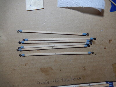
Have 6 of the struts finished; 12 more to go. I had difficulty keeping the 0.5 mm holes drilled in the ends of the first strut (1.5 mm wide) straight so I’ve drilled the others using my mini-drill press. After drilling the holes in one before binding the ends, I decided to bind the ends first and then drill them (no reason other then personal choice on the work flow). I’m using the silvery thread that comes with the kit to bind the ends (a bit like whipping rope ends) and then staining them with some watered-down gray paint to take some of the shine off. Still playing with this; haven't gotten too far in so may change my approach here.

Lots happening this week on the work front so I may not get much done on the struts until next weekend.

DSCN8398.JPGDSCN8399.JPGDSCN8400.JPGDSCN8401.JPGDSCN8404.JPGDSCN8407.JPG
 
20220131

Managed to get all of the struts finished this past week and the gas tank & radiator installed on two of them. After giving it a lot of thought I decided to wrap the strut ends with wire instead of thread. I wasn’t able to find any really thin wire (0.25 mm) in the stores near me so I went with 0.5mm; a bit thicker but it still (in my opinion) turned out nice. For the struts that I had previously finished, I removed the thread and wrapped the ends with wire. Once I had the struts completed, I finished them with a couple of coats of clear, matte finish. I put a length of the wire inside the gas line to keep that rubber tubing from crimping when it was routed to join the fuel lever.

Over the next week we’ll see how it starts to all come together. Installation of the struts, joining the wings and doing the rigging will, I’m sure, make for an interesting time.

DSCN8412.JPGDSCN8415.JPGDSCN8417.JPG
 
Hello John,

I kind of stumbled by accident on your blog of your Wright brothers build. Although I'm currently rather involved in the build of the Bluenose schooner, I'm having my eyes already peeled for a next build. Although the options are numerous, I find that I can't fully disregard my previous professional career; airframe designer. It could very well be that my next build may be a WWI or WWII aircraft, still very undecided. That's why I am very interested in your build.

Happy building,

Johan
Johan,

Thanks for the kind note. This has definitely been different then building airplanes in plastic or balsa & tissue. Right back to the dawn of aviation. It's been fun but work is definitely getting in the way of hobby right now. Hoping to be able to get an hour or so each evening to work on it.

-John
 
20220220

It’s been a while since my last post; busy times at work leaving little time to sit in front of the screen and type up thoughts. No apologies for the length here.
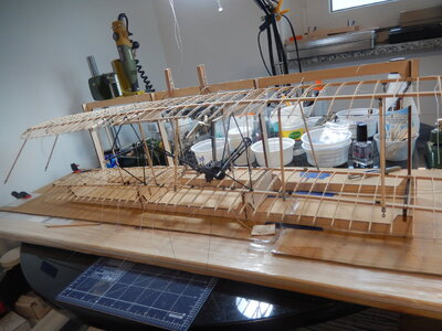
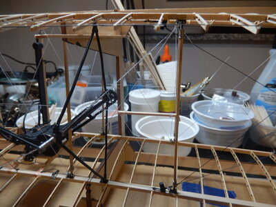
Progress has been slow at times – but steady. Several re-mountings of strut supports were required – mostly because I twisted them while installing the struts. Have to say that working with small amounts of epoxy is a bit of a pain.

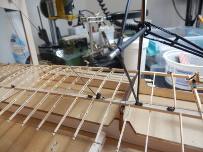
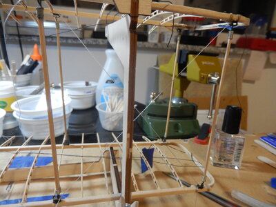
Installed the struts on the underside of the top wing first and then started adding the bracing wires (rigging thread supplied with the kit).
DSCN8418.JPGDSCN8420.JPG
At this point the vagueness of the instructions became apparent (see the figure) so I spent a bit of time looking at the photos of the Wright Flyer on the Smithsonian website. When I decided how many wires are at each strut support and which what they go (side to side/back to front) I made a sketch I could use to keep me on track.
DSCN8421.JPGDSCN8422.JPG
Once the wires were on the top wing it was time to place that on the build jig – wires (thread) everywhere! – connect the struts to the bottom wing and rig the wires to the bottom wing strut supports.
DSCN8423.JPGDSCN8424.JPG
Overall tying off the bracing wires went smoothly; I found I got into a rhythm – find a wire, identify which direction it goes and where it is tied off, fix it in place with a dab of CA, ties the knot, fix with CA, trim excess with razor knife, repeat with next wire. I temporarily held the wires in place in the strut supports with tension provided by holding the wire in clamping tweezers. I found the knots on the leading-edge spar easier to keep neat (not reaching over anything) and those on the main spar a bit more difficult (reaching over the trailing edge wire with fat fingers and long tweezers; needed to re-attach a couple of trailing ribs along the way). As I finished bracing one side of the wing, I attached the wing warping cables to their attachment points on the main spar. Along the way, there was one point where I pulled out my razor saw and cut away a bit of the jig (2 vertical slits and then remove the sliver of wood between them) so one of the bracing wires could be properly installed.
DSCN8426.JPGDSCN8428.JPG
DSCN8431.JPG
The bracing wires for the engine mounts is not shown in the instructions at the point where the wing bracing is addressed and the words used don’t paint a really clear picture. Again, reference was made to the Smithsonian pictures and to a figure close to the end of the instructions to get a clear understanding of how these bracing wires are attached.
DSCN8438.JPG
The last braces installed were the horizontal ones that run through the small holes drilled inn 12 of the struts (7 forward and 5 rearward). At the ends of the rear horizontal bracing wire, wooden stays are installed by tying them to the bracing wire.
DSCN8439.JPGDSCN8440.JPG
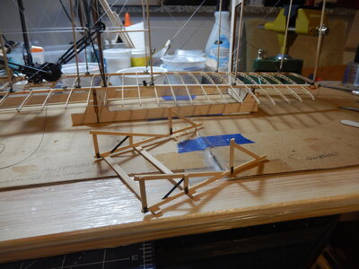
The landing skids were constructed by building them right on the plans. No dimensions are provided so I first set the building jig over the landing skid plan to make sure the plan fit properly. Then I just cut the wood pieces to the lengths shown on the plans and once the glue dried had the landing skids. Painted the hardware black to simulate the ironwork the Wright’s used and then laid the wing building jig upside down to glue the skids in place. I still have to install the 8 bracing wires that go from the skids to the bottom wing; will do that now that the model is off the building jig. There is a note (with a picture) on the plans to chamfer between the arrows – it took me a bit to figure out this referred to several sets of dimensioning arrows that do not have dimensions (or anything referring to the note). Consequently, the chamfering was not done until after the skids were installed on the underside of the bottom wing.
DSCN8442.JPG
DSCN8443.JPGDSCN8444.JPG
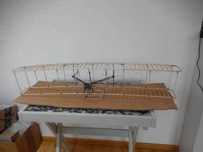
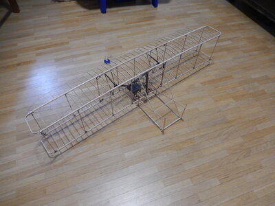
The last photos show the biplane wings and landing skids off the building jig. Work now starts on the elevators, rudders and launching dolly.
DSCN8445.JPGDSCN8446.JPG
DSCN8447.JPG
 
20220305

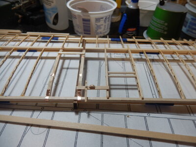
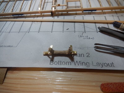
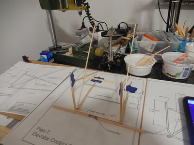
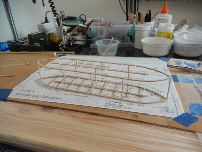
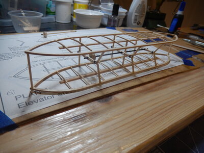
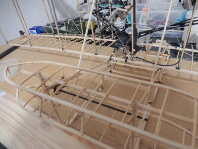
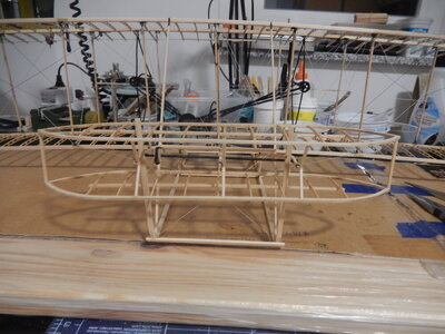
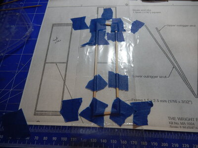
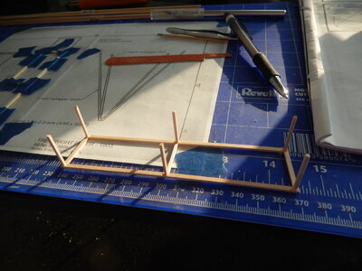
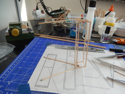
Since I last posted I have completed the elevator control frame (except for the front roller) – the part of the airframe that connects the elevators to the wings. I started out building the frame on the plans – built right & left halves and connected them together with the upper and lower crosspieces. When I checked the fit against the wings, I noticed that it didn’t seem like it was going to fit. I checked my work and all seemed OK but something was off. Simple solution – disassemble (lots of acetone used) and start over (it can be hard to make this decision but occasionally the situation needs to be faced and the decision to start over made). This time I built the frame starting at the undercarriage and made sure everything was lined up properly as I went along. When I had the skids, uprights and lower crosspiece assembled I recut the long diagonal braces that attach the frame to the upper wing (the originals were off just enough that new ones were needed). Once everything was glued in place, the self-adhesive brass tape was used to form the metal attachments that connect the elevator control frame to the wings and undercarriage.

I’m sure that the issue is related to the undercarriage being just a couple of mm taller than it should have been (even though it was built according to the plans). Minor errors carry through and need, eventually, to be dealt with.

All OK again. The next step is to form the roller that goes on the bottom of the lower crosspiece. Once that is done, I’ll start on the elevators.

DSCN8449.JPGDSCN8450.JPGDSCN8452.JPGDSCN8455.JPG
 
20220314

Back to working with little fiddly bits this past week…

Completed the front roller and frame. Have it set aside for now; will glue it on to the lower front of the elevator frame later when I’ve assembled the launching dolly.

DSCN8457.JPGDSCN8468.JPG

The 2 elevator ‘wings’ went together quite easily. Patience required so none of the pieces get accidentally broken. The difficult part came with assembly the 2 elevator ‘wings’ together using the struts – 6 of which are straight-forward cuts off the wood stock (the straight struts) and 3 that need to be created from smaller pieces as they resemble sideways ‘V’s. The 3 ‘V’s were created with arms longer than needed and then cut/filed to fit after the 2 ‘wings’ were assembled to the 6 vertical struts (I made the first one to fit the plan; it was too short so I decided to go with the ‘arms too long; trim to fit’ method).
DSCN8460.JPGDSCN8461.JPGDSCN8462.JPGDSCN8463.JPG

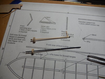
The control arms were made by cutting the stock to length to match the actual distances between front and rear struts (the center one needs to be a bit longer than the outer 2). I then drilled a 0.5 mm relief hole in the center of the arm part way back from one end using the plans as a guide. After drilling the relief hole, I carefully split the stock and then used a toothpick to hold the halves apart while binding in 2 locations with some thread. I first sealed the thread with fingernail polish to hold it in place and then painted the bindings black to simulate the metal fittings used on the actual aircraft.
DSCN8464.JPG
Several photos from the Smithsonian website were referred to as the elevator was assembled. This was necessary as the instructions, to include the sketches & plans, leave a bit to be desired in this area of the model. For instance, from the photo I could really see which part of the control arms faces forwards and that the control arms were all on the right-hand side of the elevator struts.

NASM-A19610048000-NASM2018-10796.jpg

I have the control rods and pulleys ready to be assembled. To replicate actual pulleys, I filed a shallow groove in each so that the control chain has a place to ride in.

DSCN8467.JPG

DSCN8466.JPG
 
20220322

Elevator and rudder assemblies finished and installed; launching rail and dolly assembled; starting work on the propellors. A lot accomplished this week but the final part still to be completed.

So…the elevator assembly. Installing the control rod & pulley into the control arms between the two elevator ‘wings’ – easy. Getting the elevator assembly installed onto the elevator arms – difficult. One side (the left from the pilot’s viewpoint) went on without too much difficulty but the other side was a major pain. After trying to ‘twist’ the right hand side onto the elevator arm without breaking something I decided that a controlled break was needed. I snapped off the right hand elevator arm where it was glued to the landing skid, maneuvered the elevator assembly into position (getting it positioned correctly side-to-side took a couple of tries) then held it in place while re-gluing the elevator arm back into place. Once the arm was secured, I glued the elevator assembly to the arms and then positioned the control rod pulley. Once the pulley was in the correct position, I glued the chain and wire assembly around the control rod pulley and then ran the upper wire back towards the lower wing to use as a reference for installation of the lower control rod (the one the pilot manipulated to adjust the position of the elevators). One satisfied with the lower control rod & pulley positioning it was glued in place and then the remainder of the control chain/wire assembly installed. To differentiate the control wires from rigging, I used a black permanent marker (Sharpie) to darken them. Then it was on to the rigging of the elevator. To facilitate rigging, 0.5 mm holes were drilled in the appropriate places and then, using a needle threader, the rigging lines were attached. Starting at one end of a line, I used a small knot (glued in place) to secure the end and then threaded the rigging to the endpoint where it was held in place by CA on both sides of the hole it ran through.
DSCN8469.JPGDSCN8471.JPGDSCN8472.JPGDSCN8475.JPGDSCN8476.JPGDSCN8478.JPG


The rudder was made according to the plans. This was a straight-forward process with no issues encountered. I used the photo of the elevators on the original airplane to determine that the elevator bracing wires were attached on the outer sides of the elevator’s vertical supports. The v-shaped struts that attach the rudder to the wings was also straight forward. Before drilling the holes into the ends of the supports for the eyes, I coated the ends back about 5 mm with fingernail polish to help prevent splitting. I split the eyes that are used to attach the supports to the upper wing and the rear of the landing skids and attached them to the eyes in the ends of the support arms. Pinching the split eyes closed and then adding a bit of paint sufficiently hides the splits.

DSCN8469.JPGDSCN8482.JPGDSCN8483.JPGDSCN8485.JPGDSCN8486.JPGDSCN8488.JPGDSCN8489.JPGDSCN8490.JPG

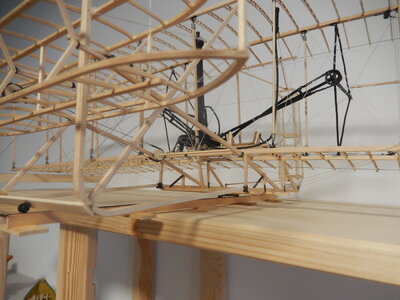
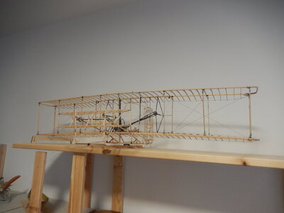
I added a board to the top of the shelves where I have the models and placed the airplane on top. As can be seen it is bigger than the shelf. This will be a consideration when it comes time to move back to the US; I’ll have to build a special case to move this model in.

The launching rail and dolly were straight forward construction. The hardest part was making sure I didn’t drop the thin sheet brass ends of the dolly rollers. Once completed the airplane was placed on the launching dolly on the launching rail. Since there is not a pilot on the plane, the right hand side (where the engine is) is a bit heavier so the model tends to tilt to the right (as did the original without a pilot). Temporarily I have a scrap piece of wood bracing the right hand tip; I’ll find a piece of clear acrylic and use that to form a permanent support.

DSCN8492.JPGDSCN8494.JPGDSCN8495.JPGDSCN8496.JPG

The propeller blanks have been glued up so that one will, when carved & sanded, be the left propeller and one the right (they turn opposite each other). Again the photo of the rear of the original is coming in handy as a reference.
 
Back
Top