HMS ALERT 1777 cutter POF by Uwek

Many thanks all for your interesting comments and also likes
Some more parts of the keel were prepared and they fit all very well.......
I hope to show you in the evening already more
Keel.jpg
 
I just checked the "keel-jig" with the available drawing, only to be sure.....
and it fits very well, so if the keel fits into the keel-jig, than the keel will fit also very good into the main jig and with this into the final "model".
IMG-3749.jpg

IMG-3750.jpg
 
Yesterday I wanted also to see how Trident Model developed the "frame-Jigs", so I made a break from the keel and took a closer look at the frame-parts and the principle idea of the jigs.

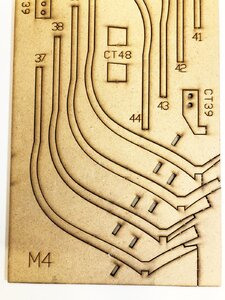
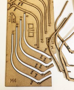
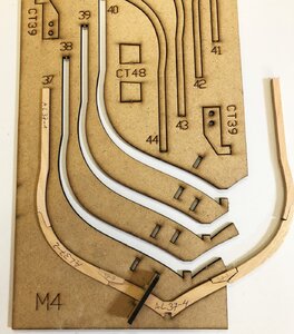
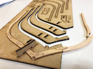
Let us have a closer look - this is one of the laser-cut boards for such a "frame-jig"
IMG-3751.jpg

So the first step is to remove the "frames" - I numbered the frames (maybe they will be necessary for something, but usual not)
IMG-3752.jpg

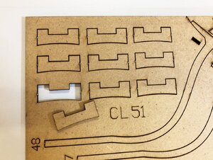
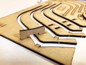
Without any stiffeners the jig would be too fragile and weak - so we need these parts
IMG-3753.jpg

with these elements the jig is very rigid
IMG-3754.jpg

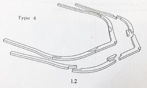
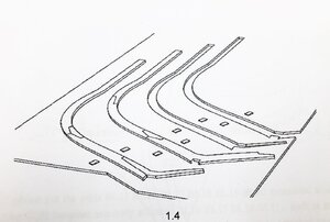
This is a typical sketch showing the elements of one frame in principle
IMG-3761.jpg

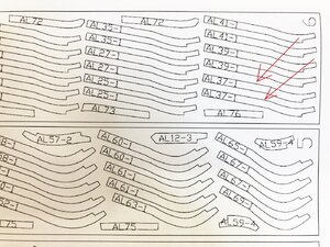
Now the real cherry floor timbers, cocks, futtocks and top timbers - For reference I was choosing the frame 37 which is midship and a double frame
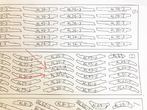
First was the search on which wooden boards the necessary parts are - It is a little bit tricky to find the parts in the manual, but I am sure with the time no problem
IMG-3755a.jpg

IMG-3756a.jpg

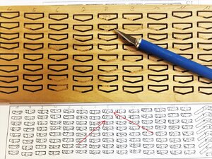
Also each chock is exactly defined, due to the fact, that they have from frame to frame some very small but important differences, so also here you have to search for the correct ones - at the end of my knife you can see the correct ones for frame 37
IMG-3758a.jpg

tight fitting but fitts
IMG-3759.jpg

IMG-3760.jpg

The idea is to glue one side of the frame, and prepare the other side, when the glue is dry
This can be effective, if you prepare the four half frames on one "frame-jig", so here 37, 38, 39 and 40

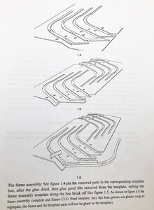
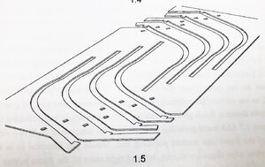
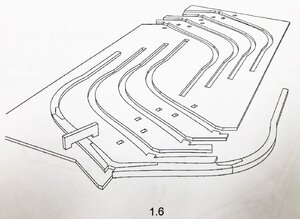
For a better understanding you can find in the following the working steps in sketches from the manual
IMG-3763.jpg IMG-3764.jpg

IMG-3765.jpg IMG-3766.jpg
 
Very good progress Uwe. I think, at this point, there shouldn't be anyone who may still in doubt about the quality of the kit engineering.

On another hand, you set such a high bar with your detailed build log (as always), it will be hard to match for the rest of us! Thumbsup
 
It is recommended to use fresh film for isolation
Yes , I will do for the first frame I will glue - a very good photos showing the thin folio (which was also mentioned in your manual), so that the frame is not glued together with the jig.
 
On another hand, you set such a high bar with your detailed build log (as always), it will be hard to match for the rest of us! Thumbsup
It is only because I am the first (and only) one here in SOS having the kit in hand, so I want also to show some of the highlights of the kit before I really start with the work - It is also later on maybe helpful for everybody following me in this group build.......
 
NO PINS, NO PINS, NO PINS, BRAVO, SHOW MORE HOW THEY WORK TO ME I THINK THE MOST IMPORTANT PART OF THE KIT BETTER NOT GET THIS WRONG IN ANY WAY, BTW WHAT DOES THE 1.2 ETC INDICATE. GOD BLESS STAY SAFE YOU AND YOURS DON
 
NO PINS, NO PINS, NO PINS, BRAVO, SHOW MORE HOW THEY WORK TO ME I THINK THE MOST IMPORTANT PART OF THE KIT BETTER NOT GET THIS WRONG IN ANY WAY, BTW WHAT DOES THE 1.2 ETC INDICATE. GOD BLESS STAY SAFE YOU AND YOURS DON
Hallo Don,
no pins any more ;) Yes, it looks like with these jigs the form of the frames can be achieved, so that the joints between the frame elements will fit well. In principle I am used to make the frames laying on the frame drawing (the conventional way) and I get usually good results, but the new way presented by Trident is working well. Maybe for the next kit development: Frame drawings and the jigs in the kit - so that the modeler can choose the way he want to make it.
1.2 etc are the indication of the different sketches, which are mentioned in the text of the manual
 
Hi Uwe, Trident Model, Just a couple of questions regarding the new, original Framing jigs.
Firstly, I really like the principle of the frame jigs that helps to keep the frame shape exact. Any innovation in this hobby that removes frustrations and makes it more enjoyable is always welcomed.
Now for my questions:
  • Do you need long reach clamps or heavy weights on top of the frames to place vertical pressure on the pieces as the glue dries?
  • The Chocks in Uwe's dry fitted images look like they are not flush with the inside (top) edge of the frame. Do these need to be faired with the rest of the frame prior to glue up so that the Frame jig works correctly and the frames don't lose their shape?
  • I assume the MDF piece designed to stop the two sides of the jig from spreading is strong enough, which means that it will be necessary for each frame to fit exactly in the frame jig. Can you give us some detailed feedback on how the lateral pressure on this piece holds up?
Thank you, if you have answered these questions previously then I apologise in advance.
John.
 
Hi JohnA
Sorry, my English is not very good, so I need to communicate with you with the help of translation software, so I often express the meaning of the word can not express the meaning, I answer, my understanding of your question,

1. According to our test and feedback from Chinese fans, it is not necessary to use weights to assist fixation.

2. When we design the frame, we choose the density board, which is a relatively stable material. We can try our best to design

3. The auxiliary support frame on the side is used to limit the rib spacing. The time of integral grinding inside the hull can avoid rib fracture.
 
Back
Top