-

Win a Free Custom Engraved Brass Coin!!!
As a way to introduce our brass coins to the community, we will raffle off a free coin during the month of August. Follow link ABOVE for instructions for entering.
- Home
- Forums
- Ships of Scale Group Builds and Projects
- Le Coureur 1776 1:48 PoF Group Build
- Le Coureur 1776 1:48 Group Build Logs
You are using an out of date browser. It may not display this or other websites correctly.
You should upgrade or use an alternative browser.
You should upgrade or use an alternative browser.
Switching gears to the interior while waiting for some small carving tools to arrive.
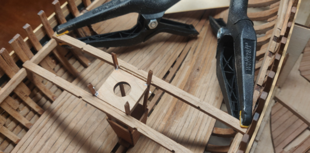
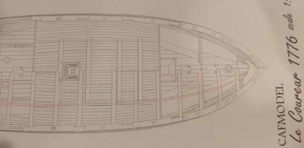
Has anyone noticed the error in the overhead deck plans? This threw me off... thought I had placed the sliding window on the front wall in the wrong position.
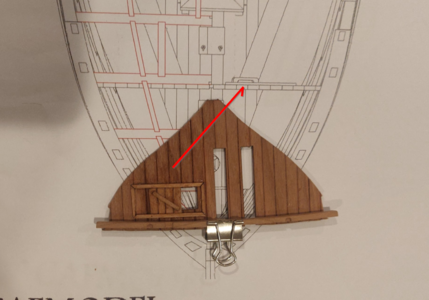
However, this plan indicates that the window does indeed go on the starboard side (as do the instructions):
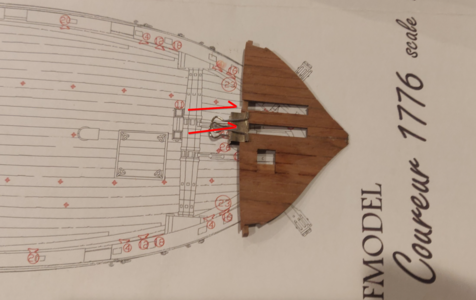

Has anyone noticed the error in the overhead deck plans? This threw me off... thought I had placed the sliding window on the front wall in the wrong position.

However, this plan indicates that the window does indeed go on the starboard side (as do the instructions):

The ballast box has a bit of spacing between it and the planks. Removing it is easy using a bit of sandpaper lightly affixed with some spray adhesive.
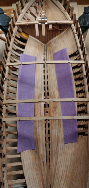
On to the deck, starting with #5. @Uwek's build log was useful here.
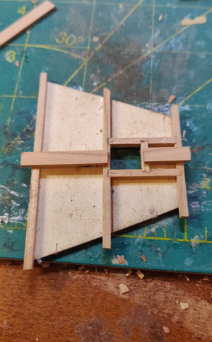
I like my floors lighter than the walls, so I'm attempting a little trick. I sand the floors and immediately apply tung oil before they have a chance to oxidize. The walls have been sitting around for months though and these turn quite a dark red. Only time will tell if the decks hold their color or if they will gradually deepen like the exposed wood.
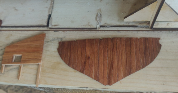

On to the deck, starting with #5. @Uwek's build log was useful here.

I like my floors lighter than the walls, so I'm attempting a little trick. I sand the floors and immediately apply tung oil before they have a chance to oxidize. The walls have been sitting around for months though and these turn quite a dark red. Only time will tell if the decks hold their color or if they will gradually deepen like the exposed wood.

Got a bit of work started on the interior. The only thing that gave me a problem was setting the rake on the front mast. I had it perfect but lo and behold, when the glue dried, the lowest piece was about 2mm too far forward. Fortunately, the hole can be expanded as necessary.
I've been applying tung oil to spots which will be difficult to reach later. However, I found that weldbond sticks to well cured tung oil just fine.
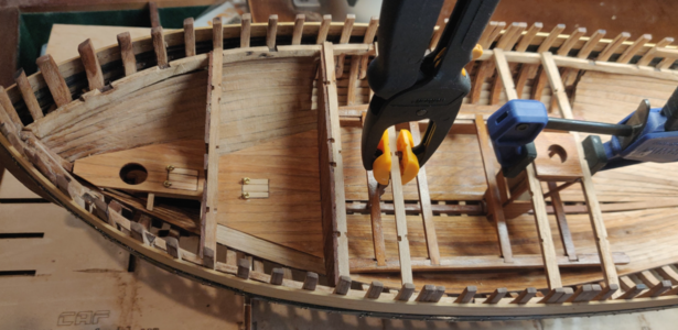
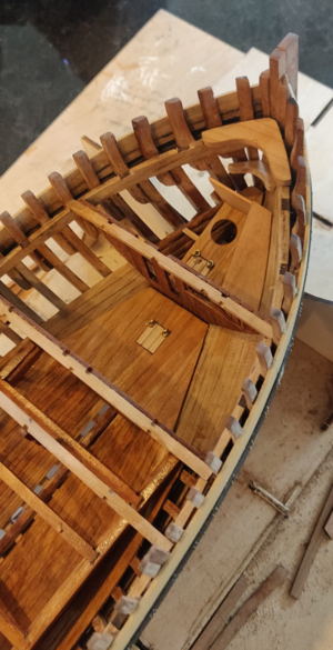
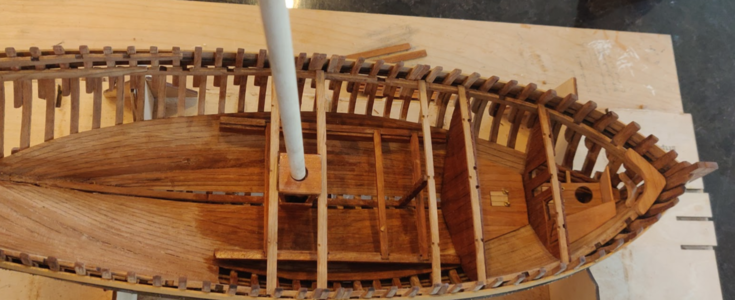
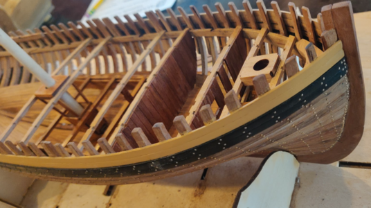
I've been applying tung oil to spots which will be difficult to reach later. However, I found that weldbond sticks to well cured tung oil just fine.


Great progress, love your 'bolting' view!
Looks very good, you have your own style, I like that.
Bravo - it is looking very good and good progress 

Only a small comment to the floor flaps / lids / covers if it is allowed:
with the lifting rings on one side it would mean, that they have a hinge on the other end. Usually such covers were only layed and if necessary lifted by two people. so the rings were usually diagonal staggered in reverse order.
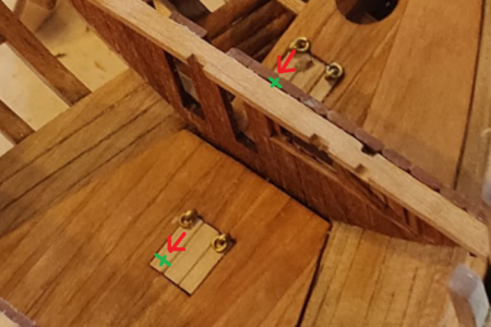
and maybe you could consider to blacken them with black brass (or something else) or paint them black


Only a small comment to the floor flaps / lids / covers if it is allowed:
with the lifting rings on one side it would mean, that they have a hinge on the other end. Usually such covers were only layed and if necessary lifted by two people. so the rings were usually diagonal staggered in reverse order.


and maybe you could consider to blacken them with black brass (or something else) or paint them black
BTW: I like your painting schema with the black wales and the occre yellow paint of the planks above the wales - I am now considering this also 
Thank you for pointing out the configuration of the brass rings. I was wondering about this. The instructions and the plans show two different configurations. Also the Boudriot plans show a hatch on top with the rings on one side, so it seemed ambiguous to me.
Now I am not sure if I will fix them or leave the same.
Now I am not sure if I will fix them or leave the same.
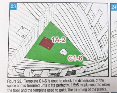
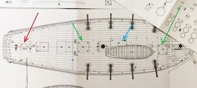
Boudriot´s deck plan (there is no drawing showing the interior) is showing bigger hatches with four triangle rings (green arrows) and one smaller with two rings (red arrow) diagonalThank you for pointing out the configuration of the brass rings. I was wondering about this. The instructions and the plans show two different configurations. Also the Boudriot plans show a hatch on top with the rings on one side, so it seemed ambiguous to me.
Now I am not sure if I will fix them or leave the same.
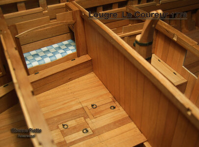
the interior is shown also at Etiennes 1:24 model also with the diagonal

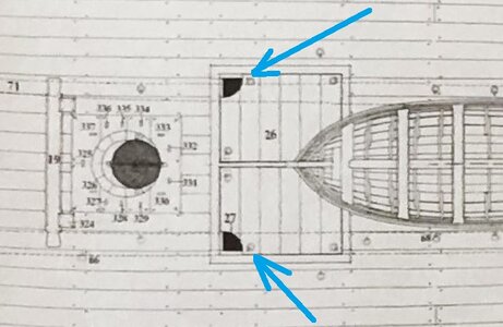
BTW: what I just realized..... on the Boudriot drawings rings are missing on the main hatch directly next to the holes / openings for the anchor cables (blue arrow) -> only to keep this in mind for later
this is correctly shown on the drawings of the Le CERF also from Boudriot
- Joined
- Sep 28, 2020
- Messages
- 285
- Points
- 168

If you watch the left picture, the diagonal rings make no sense for me. If I was a sailor and had to open the hatch, I would prefer both rings at one side to grab it and pull with both hands. If two sailors have to open the hatch, where would they go? At one side the cabinet, at the other the mast (or pump well?) Or jumping over the now open hole?Boudriot´s deck plan (there is no drawing showing the interior) is showing bigger hatches with four triangle rings (green arrows) and one smaller with two rings (red arrow) diagonal
View attachment 227528
the interior is shown also at Etiennes 1:24 model also with the diagonal
View attachment 227524 View attachment 227525
BTW: what I just realized..... on the Boudriot drawings rings are missing on the main hatch directly next to the holes / openings for the anchor cables (blue arrow) -> only to keep this in mind for later
this is correctly shown on the drawings of the Le CERF also from Boudriot
View attachment 227527
I was thinking the same thing. I could see no reason for diagonal rings in such cramped quarters.If you watch the left picture, the diagonal rings make no sense for me. If I was a sailor and had to open the hatch, I would prefer both rings at one side to grab it and pull with both hands. If two sailors have to open the hatch, where would they go? At one side the cabinet, at the other the mast (or pump well?) Or jumping over the now open hole?
Mayb it was a little bit tricky to open them, especially if there is small free space - maybe they had four rings.If you watch the left picture, the diagonal rings make no sense for me. If I was a sailor and had to open the hatch, I would prefer both rings at one side to grab it and pull with both hands. If two sailors have to open the hatch, where would they go? At one side the cabinet, at the other the mast (or pump well?) Or jumping over the now open hole?
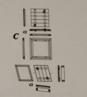
All what I can say is the fact, that on french ships such small hatches seems to have every time shown 2 rings diagonal and the bigger hatches (heavier) four rings on each edge
such covers were not opened very often - and to move a cabinet should be possible by strong seamen
See. f.e. also the hatch cover drawn by Gérard Delacroix on his Le Rochefort
- Joined
- Sep 28, 2020
- Messages
- 285
- Points
- 168

On the left picture it is clear, plenty of space in every direction.
Just broke another spar of my coureur......
In the beginning I thought this could never happen, they are very stable, but this was number 4.
Just a few left and I am getting sloppy.
Just broke another spar of my coureur......
In the beginning I thought this could never happen, they are very stable, but this was number 4.
Just a few left and I am getting sloppy.
Good, that you mentioned it - so it is time to make an update of your building logOn the left picture it is clear, plenty of space in every direction.
Just broke another spar of my coureur......
In the beginning I thought this could never happen, they are very stable, but this was number 4.
Just a few left and I am getting sloppy.
Nice little cabinet. When making this, note that the side panels are not symmetrical but rather, the top has a slight angle to it. This results in the cabinet's top surface having a slight downward slope when mounted.
The tabs were not a close fit at all as originally cut. This took some adjustment using a very tiny chisel to get the sides more or less flush.
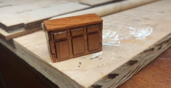
The tabs were not a close fit at all as originally cut. This took some adjustment using a very tiny chisel to get the sides more or less flush.

The galley oven was a lot of fun. I started by bending some brass wire into the shape of small rails. I ended up using 1.0mm wire instead of 0.8mm to give them a little more heft. Holes were carefully drilled into the clay floor.
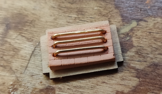
The sides were straightforward for the most part but two notes. First, the clay walls were not flat by a long shot. I sanded the backs flat but the front of several of the pieces were warped. No matter, as you'll see next.
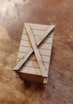
The side braces were glued on. I wasn't careful enough to get the joinery exactly right but again, no matter.
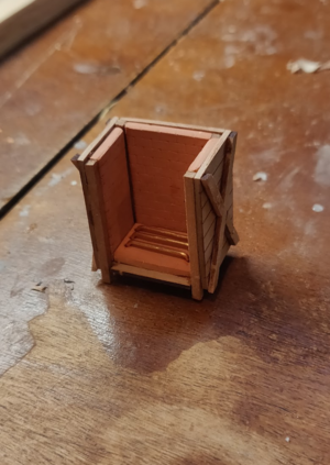
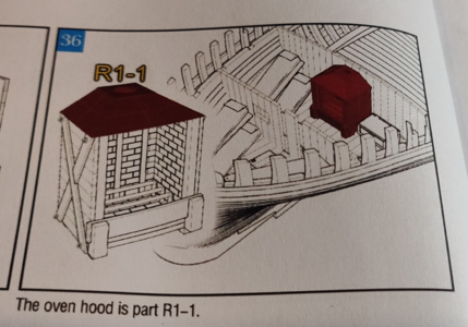
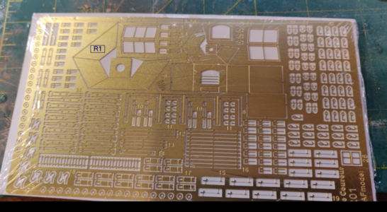
Took me a bit to figure out where part R1 was located. This was aggravating because I've had several missing pieces so far and I thought this was one of them. However, it was located on the brass sheet included with the kit.
Rustoleum black metallic spray paint was used to give the piece a cast iron look. To my chagrin, I discovered that my 1mm brass wire was coated so I roughed it up with a file than applied some black paint to it as well.
However, if you have ever worked with traditional ovens, you know that this is far from accurate:
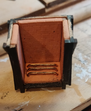
The reason is that these ovens, whether fueled by wood, charcoal or coal, produce large amounts of ash and soot. This was replicated with more black paint and then finely powdered charcoal was rubbed on while the surface was still wet.
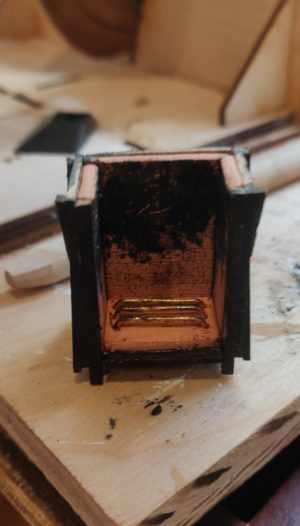
Dilute weldbond was brushed on the bottom and hardwood ash was sprinkled on.
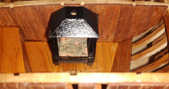
In this manner, a realistic oven was made. Note that in the photo below, the flash shows that some of the wood is still visible on the lower edge. This was later covered with another coat of black.
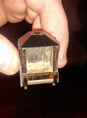
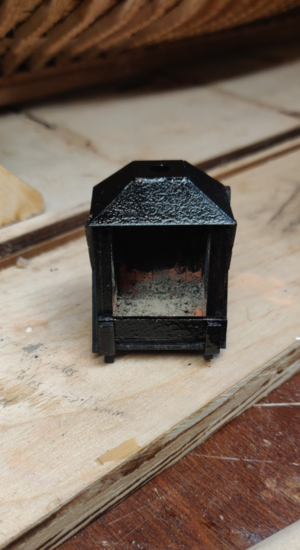
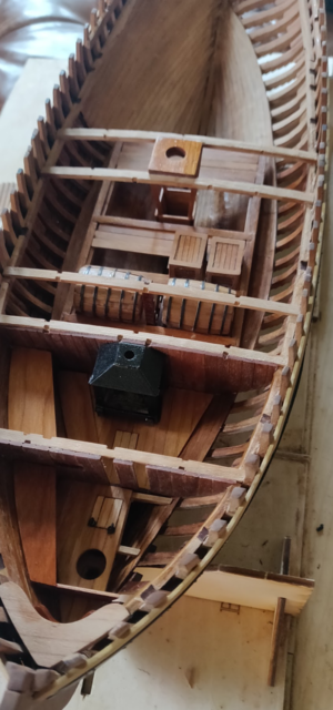

The sides were straightforward for the most part but two notes. First, the clay walls were not flat by a long shot. I sanded the backs flat but the front of several of the pieces were warped. No matter, as you'll see next.

The side braces were glued on. I wasn't careful enough to get the joinery exactly right but again, no matter.

Took me a bit to figure out where part R1 was located. This was aggravating because I've had several missing pieces so far and I thought this was one of them. However, it was located on the brass sheet included with the kit.


Rustoleum black metallic spray paint was used to give the piece a cast iron look. To my chagrin, I discovered that my 1mm brass wire was coated so I roughed it up with a file than applied some black paint to it as well.
However, if you have ever worked with traditional ovens, you know that this is far from accurate:

The reason is that these ovens, whether fueled by wood, charcoal or coal, produce large amounts of ash and soot. This was replicated with more black paint and then finely powdered charcoal was rubbed on while the surface was still wet.

Dilute weldbond was brushed on the bottom and hardwood ash was sprinkled on.

In this manner, a realistic oven was made. Note that in the photo below, the flash shows that some of the wood is still visible on the lower edge. This was later covered with another coat of black.


Last edited:
Love your oven, especially ash representation!

