- Joined
- Sep 3, 2021
- Messages
- 5,197
- Points
- 738

 |
As a way to introduce our brass coins to the community, we will raffle off a free coin during the month of August. Follow link ABOVE for instructions for entering. |
 |
 |
The beloved Ships in Scale Magazine is back and charting a new course for 2026! Discover new skills, new techniques, and new inspirations in every issue. NOTE THAT OUR FIRST ISSUE WILL BE JAN/FEB 2026 |
 |


Thank you, Johan. I am sure the goldfish-shape was no coincidence. With the advent of the 17th century all Dutch ships were built with a specific purpose in mind - be it cargo ships (like the Fluyt), merchantmen (like the VOC ships) or men-o-war. The WB and the Geunieerde Provincien were probably some of the last well-known ships which were built without these encumbrances. With their sailing characteristics as the prime objective, the goldfish analogy therefore makes sense!Very nice progress Heinrich!
Looking forward to the scratch-build part of your journey.
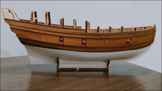
By the way, it just struck me how the hull looks remarkably like the body of a fish. Can't be coincidental.
(The goldfish picture is not mine, so I won't take credit for it.)
View attachment 327743

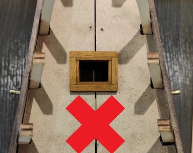

Can your very fine back saw do you any good in this area?As I said yesterday, the next step would be to install the hatches and to plank up the rear bulwarks to their correct height.
View attachment 327867
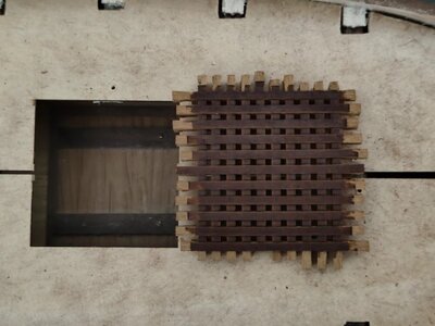
I started with the gratings and even though this is always a finnicky part of the build, this went very well. Here it is shown assembled, just prior to gluing.
View attachment 327869
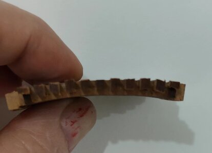
Even the required curvature was achieved without sanding. Sanding will of course take place, but that will be for finishing, not for creating the curvature.
View attachment 327870
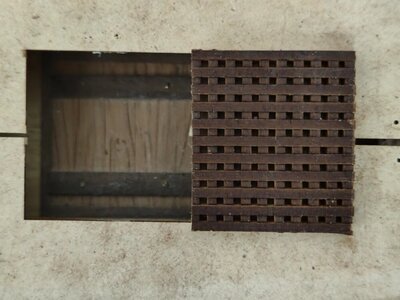
Cut to the correct size (no sanding yet) and ready to have the frame installed. In the past (and on WB#1) I have always mitered the frame joints, but on the WB that is incorrect. The frame needs to be created from half-lap joints. Before I tried my hand at doing that on the main hatch, I first practised by making the smaller, rear hatch.
View attachment 327872
Clearly that hatch will never be allowed to see the light of the day, so a re-do is required. The problem though is that in cutting the 1.5mm x 4mm planks for the hatch, this happened!
View attachment 327873
If you have thought that I have exaggerated in the past about how tough oak is to cut, here is the proof. And as my dear friend, Mr Murphy would have it, I have plenty of blades, but no more knives! Ah well, sit back and relax.

Murphy was, is and always will be lurking around, waiting for the most inopportune moment to strike and to strike without mercy. I honestly cannot say he or she is a great friend of mine.As I said yesterday, the next step would be to install the hatches and to plank up the rear bulwarks to their correct height.
View attachment 327867
I started with the gratings and even though this is always a finnicky part of the build, this went very well. Here it is shown assembled, just prior to gluing.
View attachment 327869
Even the required curvature was achieved without sanding. Sanding will of course take place, but that will be for finishing, not for creating the curvature.
View attachment 327870
Cut to the correct size (no sanding yet) and ready to have the frame installed. In the past (and on WB#1) I have always mitered the frame joints, but on the WB that is incorrect. The frame needs to be created from half-lap joints. Before I tried my hand at doing that on the main hatch, I first practised by making the smaller, rear hatch.
View attachment 327872
Clearly that hatch will never be allowed to see the light of the day, so a re-do is required. The problem though is that in cutting the 1.5mm x 4mm planks for the hatch, this happened!
View attachment 327873
If you have thought that I have exaggerated in the past about how tough oak is to cut, here is the proof. And as my dear friend, Mr Murphy would have it, I have plenty of blades, but no more knives! Ah well, sit back and relax.

Thank you very much Johan. The grating came out very well, the rear hatch not so well. It would have been so much easier just to miter the joints at 45 degrees.Murphy was, is and always will be lurking around, waiting for the most inopportune moment to strike and to strike without mercy. I honestly cannot say he or she is a great friend of mine.
Your grating looks great by the way, but frankly, I don't expect anything less...

Only one way forward then; join the re-do fraternity!Thank you very much Johan. The grating came out very well, the rear hatch not so well. It would have been so much easier just to miter the joints at 45 degrees.


That blade is a very good suggestion, Peter! Whether I can find it in China though is a different storyThese ships where always a bit on the rough side my friend, when they build ships in 1600, they did not spend much sandpaper on them.
Cutting your oak planking goes perhaps a bit better with a blade like this:View attachment 327887


Alvast bedankt Piet. Deze zou ik op Taobao moeten kunnen vinden. Met WB #2 heb ik de Japanse zaag bij Hans besteld wat briljant is maar voor dit soort zagen zijn de tanden te grof. Ik zal morgen een plan maken. Gelukkig voor de rest van de huidbeplanking kan ik mijn zijsnijder en vijlen gebruiken.Je hebt al een paar suggesties gehad Heinrich, maar hier doe ik het al jaren mee...
View attachment 327913

My challenge is that half the time I do not have any idea how to find the tools in China.
Thank you, my friend. Until the deck planking is done, the inner planking has been completed and the hatches are done, she will look a bit on the "rough" side, but that is just the nature of the build.

Much appreciated, Roger!I see nothing “rough”, I see a wonderful rendition of a fascinating ship, which reflects your hours of research. I too am looking forward to the next stages of your build.
Good morning Heinrich. Wow, you certainly got your head down and accomplished plenty since my last visit here. I was concerned with your deck gap due to your widening the bow area. I see you will cover this “ easily” (well nothing is easy with this hobbyDear Friends
For the last three days, the hammer went down hard in the Lincoln Shipyard in Nantong.
View attachment 327667
Gunports on the Port Side were all cut-out, those which needed to be closed up, were closed up, and those which required interior framing, were framed.
View attachment 327668
Thereafter the Port Side cannons were constructed. This picture shows the final mounting blocks in the process of manufacture. All were filed and sanded and covered with CLOU stain.
View attachment 327665
Gunports on the starboard side were definitively mounted (above and below)
View attachment 327669
Even though it appears as if the stern most cannon sits too high in the gunport, that is just an optical illusion. For reference look at the first picture and you will see that it exits exactly in the middle of the port.
View attachment 327666
Gunports on the Port Side were permanently installed (above and below).
View attachment 327670
View attachment 327671
As you will remember, I have already dry-fitted the deck halves previously, so all that had to be done now was to cut out the openings for the hatches.
View attachment 327672
Port side deck half fitted. The main mast that is visible in the background, was borrowed from WB#1 to ensure the correct deck alignment. Push pins were used to ensure that the deck lies flat and true on the deck beams.
View attachment 327681
The starboard side of the deck in position. The gap that developed towards the bow between the two deck halves is indicative of the amount that I have increased the width of the hull by. It may not seem like much, but this picture does not tell the full story. On WB#1 the deck was far too wiide to fit unless the excess around the edges were removed. On WB#2, nothing was removed - and despite that - the two deck halves would still not meet in the middle. The bow on WB#2 is considerably wider than that of its sibling.
View attachment 327682
Counting from the stem, bulkheads #1 to #6 were removed,
View attachment 327683
The deck beam that ran in the middle of the large hatch was sawn out,
View attachment 327684
And so was the deck beam that ran along the front edge of the smaller hatch.
View attachment 327685
And finally, an overview shot of where I am this afternoon. This evening I am going to have supper with two of my colleagues so I doubt that anything further will happen today.
This is the point of the construction that I have dreamt about. From here (even though I will be using the kit components that coincide with my research), much will be scratch-built. This is the part by which the model will stand or fall - not from a construction point of view, but from the point of something that is historically worthy, and which can bear out the hundreds of hours of research that has gone into it. I am excited.

Hi Grant. It's great to have you back! I trust that the office work was lucrative, and more importantly, profitable. Yep, I got a few things done and hope to post some more updates tonight. I will still make a call on the gap when I start the planking, but I think it should be OK.Good morning Heinrich. Wow, you certainly got your head down and accomplished plenty since my last visit here. I was concerned with your deck gap due to your widening the bow area. I see you will cover this “ easily” (well nothing is easy with this hobby) with the 4mm deck planks, so all will be spot on as always Heinrich. All looking fantastic- you owned it! Cheers Grant
Hi Heinrich.Dear Friends
For the last three days, the hammer went down hard in the Lincoln Shipyard in Nantong.
View attachment 327667
Gunports on the Port Side were all cut-out, those which needed to be closed up, were closed up, and those which required interior framing, were framed.
View attachment 327668
Thereafter the Port Side cannons were constructed. This picture shows the final mounting blocks in the process of manufacture. All were filed and sanded and covered with CLOU stain.
View attachment 327665
Gunports on the starboard side were definitively mounted (above and below)
View attachment 327669
Even though it appears as if the stern most cannon sits too high in the gunport, that is just an optical illusion. For reference look at the first picture and you will see that it exits exactly in the middle of the port.
View attachment 327666
Gunports on the Port Side were permanently installed (above and below).
View attachment 327670
View attachment 327671
As you will remember, I have already dry-fitted the deck halves previously, so all that had to be done now was to cut out the openings for the hatches.
View attachment 327672
Port side deck half fitted. The main mast that is visible in the background, was borrowed from WB#1 to ensure the correct deck alignment. Push pins were used to ensure that the deck lies flat and true on the deck beams.
View attachment 327681
The starboard side of the deck in position. The gap that developed towards the bow between the two deck halves is indicative of the amount that I have increased the width of the hull by. It may not seem like much, but this picture does not tell the full story. On WB#1 the deck was far too wiide to fit unless the excess around the edges were removed. On WB#2, nothing was removed - and despite that - the two deck halves would still not meet in the middle. The bow on WB#2 is considerably wider than that of its sibling.
View attachment 327682
Counting from the stem, bulkheads #1 to #6 were removed,
View attachment 327683
The deck beam that ran in the middle of the large hatch was sawn out,
View attachment 327684
And so was the deck beam that ran along the front edge of the smaller hatch.
View attachment 327685
And finally, an overview shot of where I am this afternoon. This evening I am going to have supper with two of my colleagues so I doubt that anything further will happen today.
This is the point of the construction that I have dreamt about. From here (even though I will be using the kit components that coincide with my research), much will be scratch-built. This is the part by which the model will stand or fall - not from a construction point of view, but from the point of something that is historically worthy, and which can bear out the hundreds of hours of research that has gone into it. I am excited.
