• LUCZORAMA SHIPWRECK SCAVENGER HUNT GIVEAWAY. 4 Weeks of Fun • 1 Legendary Prize ((OcCre’s Fram Ship)) • Global Crew Welcome!
    **VIEW THREAD HERE**

Building a Cutter

Joined
May 9, 2024
Messages
2,763
Points
588

I hope some members find this interesting and useful. If anyone spots any errors along the way PLEASE feel free to point these out so I can correct them. I have not built a clinker (lapstrake) boat for a while and do not recall seeing a build log of a cutter built from scratch. using only handheld tools, (both power and manual). I thought/hoped this log might encourage some members to have a go at a scratch build knowing planers, mills, table saws and the like are not necessary. I cut my own strip wood because I have a supply of rough stock on hand but this can be purchased in sheets from a number of vendors around the world then slit with a ruler and scalpel such as an Xacto knife. Dimensions will be from the original drawing or from David Steel's The Elements and Practice of Naval Architecture. The scantlings Steel gives for cutters includes 21 foot and 16 foot boats but not an18 foot cutter which is the subject of this build. Looking at the breadth, for example, for the 21 foot cutter that Steel includes, it's 6' 7". The breadth on the drawing below of the 18 footer
is 6' 6 1/2" At a scale of 1:36 this is only 0.35mm so probably not noticeable. I will use the drawing for dimensions on such things as the thwarts, but for things not shown, such as footwaling, I will rely on the scantlings from Steel. If there is a wide disparity in some parts for the scantlings for a 16 footer and a 21 footer in Steel's chart, I will use a figure in between the two.

The original drawing shown below is ZAZ 7030 from RMG. https://www.rmg.co.uk/collections/objects/rmgc-object-86821
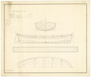
1749234956087.png
I inserted this drawing into my CAD program, but the original drawing can be printed at any print shop in whatever scale the builder would like if no CAD program is going to be used.

Once inserted into the program I scaled it to 1:36. NB: If anyone wants a copy of the drawings that will be following in this build log please feel free to PM me your email address and I would be very happy to send them to you. I can send as PDFs, JPGs or PNGs or in DWG or DXF for those using CAD.

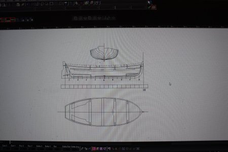
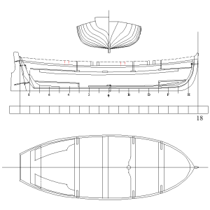
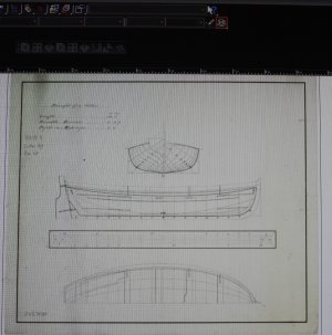
Below are two photos (poorly done, sorry) of the screen of the original drawing that was inserted followed by the first tracing. These are both adjusted to 1:36 scale.

Allan
1749250471397.jpeg

Tracing on the CAD screen
1749250502467.jpeg

Tracing saved to file.
1749250604228.png
Allan
 
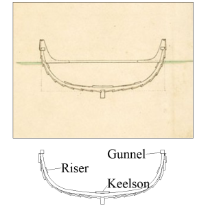
Most contemporary drawings that I found for cutters in this size range do not have a cross section showing the lapstraking. I did find one for a 22 found cutter and reduced it's breadth to match that of the 18 footer to estimate the breadth of the planking. Steel does not give the breadth of the bottom planks in the list of scantlings so this drawing is a big help. He does give the thickness at 5/8" and the drawing shows the planks are 7.5" broad with an overlap of 1.5" . The keelson and risings sizes are sized based on the Steel scantlings.
Allan
1749291568862.png
 
I hope some members find this interesting and useful. If anyone spots any errors along the way PLEASE feel free to point these out so I can correct them. I have not built a clinker (lapstrake) boat for a while and do not recall seeing a build log of a cutter built from scratch. using only handheld tools, (both power and manual). I thought/hoped this log might encourage some members to have a go at a scratch build knowing planers, mills, table saws and the like are not necessary. I cut my own strip wood because I have a supply of rough stock on hand but this can be purchased in sheets from a number of vendors around the world then slit with a ruler and scalpel such as an Xacto knife. Dimensions will be from the original drawing or from David Steel's The Elements and Practice of Naval Architecture. The scantlings Steel gives for cutters includes 21 foot and 16 foot boats but not an18 foot cutter which is the subject of this build. Looking at the breadth, for example, for the 21 foot cutter that Steel includes, it's 6' 7". The breadth on the drawing below of the 18 footer
is 6' 6 1/2" At a scale of 1:36 this is only 0.35mm so probably not noticeable. I will use the drawing for dimensions on such things as the thwarts, but for things not shown, such as footwaling, I will rely on the scantlings from Steel. If there is a wide disparity in some parts for the scantlings for a 16 footer and a 21 footer in Steel's chart, I will use a figure in between the two.

The original drawing shown below is ZAZ 7030 from RMG. https://www.rmg.co.uk/collections/objects/rmgc-object-86821
View attachment 523946
I inserted this drawing into my CAD program, but the original drawing can be printed at any print shop in whatever scale the builder would like if no CAD program is going to be used.

Once inserted into the program I scaled it to 1:36. NB: If anyone wants a copy of the drawings that will be following in this build log please feel free to PM me your email address and I would be very happy to send them to you. I can send as PDFs, JPGs or PNGs or in DWG or DXF for those using CAD.

Below are two photos (poorly done, sorry) of the screen of the original drawing that was inserted followed by the first tracing. These are both adjusted to 1:36 scale.

Allan

View attachment 524008

Tracing on the CAD screen
View attachment 524009

Tracing saved to file.
View attachment 524010
Allan
Always nice and interesting to see a scratch build with the start of only some basic drawings and the preparation in a CAD program, Allen.
Regards, Peter
 
Super project idea.

I'll follow, but don't like the png picture files as I'm too lazy to go through the faff converting them to consistent jpeg's.
 
I'll follow, but don't like the png picture files as I'm too lazy to go through the faff converting them to consistent jpeg's.
Sorry Pugwash I had no idea it was not possible to just click and open a PNG pic same as a jpg. Here you go in jpg. Hope this is easier. If this is better for everyone please feel free to give a shout and I will just post jpgs.
Allan
View attachment 524184

Lapstrake cross section 1.JPG
 
Thank you so very much.

When does a small cutter become a 'Jolly Boat'?
 
When does a small cutter become a 'Jolly Boat'?
Brian Lavery goes into some detail based on his research.

Not sure if this will answer your question Pugwash, but he gives the following explanation even if it is not conclusive:

The jolly boat was quite common in the early 17th century. They were between 16 and 20 feet long. There was still the occasional use in the 1680s, found on first, second, and third rates from 16 to 19 feet long. The term reappears again in the late 18th century when it was used to describe small boats of 16 to 18 feet long. These MAY have been cutters according one authority Lavery does not name. He goes on to write that another authority said that four oared cutters were sometimes called jolly boats.

Because there are kits that offer models of the Bounty jolly boat I looked at the Bligh Treatise and cannot find any mention of a jolly boat, only the five oared cutter and the launch which was the boat used on the famous voyage. He uses the word boat 228 times in the treatise, but never a mention of a jolly boat even though the timing for their reappearance fits. Again, this may be inconclusive. Hopefully some member will know an authoritative source with something more definitive.
Allan
 
Last edited:
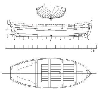
I put together a spread sheet of scantlings and double checked the first drawing. A few corrections have been made and a few questions arose as well. First, the drawing in post #8 has had a few items added and small modifications and cleaning up has been done as well. It is also posted below.
The scantlings spread sheet will follow shortly.

In the drawing I have added the footwaling and keelson. I was not sure of the breadth of the footwaling but found a contract that called for 4 inch wide boards so went with that. The keelson breadth is given in the scantlings. Thickness for both are also in the scantlings. Steel calls for ears so I added them but have some doubts that these were found on cutters circa late 18th century and early 19th century. I also added the knees aft and breasthook forward. These appear to be common so I have added them even though some contemporary drawings do not show them. I am guessing they assume any boat builder knows they would have to be there. Any input on any of these points, or anything else that does not look right would be greatly appreciated. Note that the heel of rudder has been shortened in the drawing to being closer to the scantlings and drawings of other similar boats. If the drawing is enlarged, the pintles and gudgeons have been made a bit more clear.

1749494049905.jpeg
 
Last edited:
No watered down rum on my boat.

Unlikely.

1) You cite Steel's works which focus primarily on British Royal and mercantile navies.
2) The drawing you started with is circa 1790 - 1810 (according to RMG).
3) According to Wikipedia: "In 1740, to minimize the subsequent illness, drunkenness, and disciplinary problems, British Vice-Admiral Edward Vernon ordered that the daily rum issue of one-half imperial pint (284 ml) of rum be mixed with one imperial quart (1,100 ml) of water, a water-to-rum ratio of 4:1, with half issued before noon and the remainder after the end of the working day. This both diluted its effects and accelerated its spoilage, preventing hoarding of the allowance. The mixture of rum and water became known as a "grog". This procedure became part of the official regulations of the Royal Navy in 1756 until the reduction of the ration to the "tot" in 1850. Sailors were given one-eighth of an imperial pint (1 gill; 71 millilitres) of rum daily, or 17.5 imperial oz a week. The issued ration of rum was called a "tot," and typically had a high alcohol content (54.6% ABV). This practice continued until 1970."

Therefore, unless your crew were mutineers or pirates, it was grog. :D ;)ROTFBeer
 
Last edited:
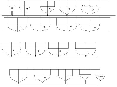
Next up was drawing the moulds. I traced the station lines then redrew the shape less the thickness of the frames to come up with these formers, one for each station line. The extension on top is there to provide space between the building board and the boat itself. I also marked the line where the planking ends and the gunwale will go on. These were drawn at full scale so they can be reduced to any model size scale drawing needed in a few seconds.
Allan
1749732869724.jpeg
 
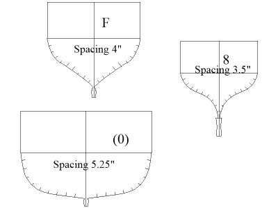
Choosing the number of strakes of planking is a bit arbitrary but I use the scantlings for the upper strake or landing strake as a guide for the breadth. In this case 10 strakes is what I came up with, but it may be fewer with broader planks. In order to plank a hull as was done on actual vessels of the time, the frames have to be marked off. I find it is just as easy to do this on the drawings at three or more stations and go from there. The spacing of course varies but with one set up forward, one midships, and one aft, it is easy enough run the planking in the proper sheer.

The planks themselves will be 1.5" wider than the spacing as they overlap with the clinker construction of the cutter except at the bow which will be addressed later. In short the breadth of each plank will go from about 5.5" at the stem to 6.75"midships to about 5" aft at the post.

I am considering going to nine strakes as in the cross section in post 8. Any thoughts from members on this would be most welcome as it does not seem to be something set in stone that I can find so far.
Thanks
Allan

1749809416097.jpeg
 
Last edited:
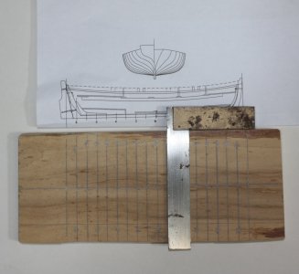
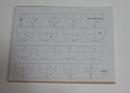
Made some sawdust today starting with the building board which is 1/2" plywood about 4"X8". A centerline was drawn on the board then using the profile drawing printed at 1:36 the location of the frame formers were marked.
1750098063420.jpeg

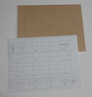
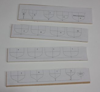
I did reduce the number of strakes to nine, matching that of the contemporary plan for a similar size cutter posted above. The formers were then printed onto a sheet of cheap label paper as I prefer it to printing on plain paper and then gluing to wood. The first pic below shows the backing sheet of the label paper. I cut a piece of plywood sheet to about the same size as the paper, if only for convenience sake. I used a hand saw only to prove a table saw was not necessary.

1750096864981.jpeg

1750096952414.jpeg
After wiping down the sheet of plywood with alcohol (so it would dry quickly) and a rag, the backing on the paper sheet was peeled off and the printed side applied to the wood.

1750097032496.jpeg
The strips of formers were then cut so they were easier to handle and hold in a vice.
1750097189973.jpeg

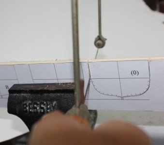
The next photo shows a former being cut with a coping saw. A scroll saw is much easier, but again, I just wanted to prove, if only to myself, this could be done with a hand saw.
1750097283315.jpeg
 
The next photo shows a former being cut with a coping saw. A scroll saw is much easier, but again, I just wanted to prove, if only to myself, this could be done with a hand saw.
Kudos to you, Allen! "Going the extra mile!"
I'm working on a scratch built-up Hoy. I was initially thinking about using a coping saw and chisels but quickly changed my mind. I just didn't want to put that much work into the build if I didn't have to. My idea of a coping saw and chisels have been replaced by a CNC router and a milling machine, LOL. :) "Hats off to ya!"
 
Last edited:
Back
Top