• Win a Free Custom Engraved Brass Coin!!!
    As a way to introduce our brass coins to the community, we will raffle off a free coin during the month of August. Follow link ABOVE for instructions for entering.

USS Constitution by Model Shipways. - First Build Log

Hull coppering can be tedious, but yours is coming along very nicely.

FWIW, I'm with Bob on the use of copper tape for coppering a hull. The wrinkles are easily dealt with by burnishing the whole thing with a plastic spoon or something similar, and it all lays down nice and smooth.
Hull coppering can be tedious, but yours is coming along very nicely.

FWIW, I'm with Bob on the use of copper tape for coppering a hull. The wrinkles are easily dealt with by burnishing the whole thing with a plastic spoon or something similar, and it all lays down nice and smooth.
DId you use the rivet wheel? Would burnishing mess with the rivets you made?
 
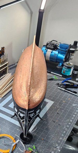
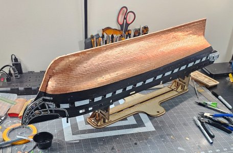
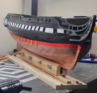
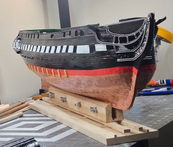
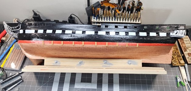
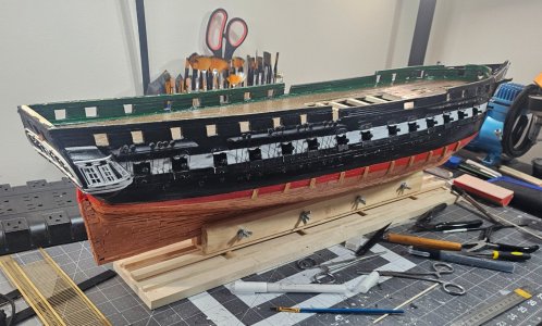
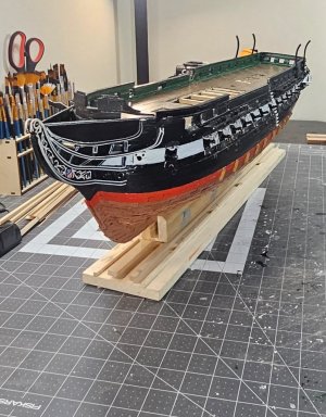
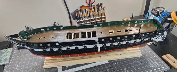
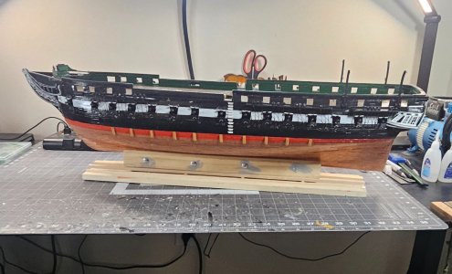
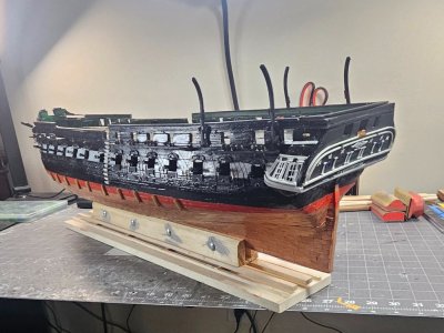
Copper plating the hull was a lot more challenging than expected because I chose the plates over the copper tape. Several builders had choices, and from what I saw, did a pretty nice job with both choices, as well as dealing with size variations between copper tape, and different copper plates with sizes either on scale or very close to it. I found this to be very tedious as well, and learned soon that when cutting the plates, which is each individual plate, that you have to go back to each individual and make sure any existing left-over metal on each side has to be trimmed or cut off, otherwise you might be left with tiny gaps that are noticeable up close. When it came to the bow and stern, I found that to be quite the challenge because it is not like bending planks. I found myself having to cut or trim the copper plate to get into making my way to the bow and stern. I also had a chance to do a little experiment as well. I started with Hunt's Practicum and then followed what my gut told me halfway through. Going back to the variations in your choice of hull coppering material, one cannot be sure that if you follow the pattern in the practicum that it would work for all of the copper materials which I found out to be true. Because everyone's Conny might vary slightly after they had planked the ship, or based on the different copper plating sizes, etc. I was left with a very small gap that I would need to fill in. I could trim the plates to use them as if it were a filler like we did during planking, but I found that to be tough because if you cannot cut it the correct size, it will not look good and you might waste plates and not have enough to complete each side and each side takes ~1,024 plates for total of 2,048. You should be left with a very small amount of left-over plates. You may need to use plates to overlap the left-over areas to be covered so that it looks decent. If done correctly, any gaps you have should be towards the underside of the boat and there will be some at the bow and stern mainly because of the sharp turns. For copper tape users, it's easier to cut to fit. Ok, back to the experiment...what I did was initially try to cut the plates to try to fit inside the gap. I found that to be too hard because the plates are hard, and you need a knife or something to cut and trimming can be tougher because you now need to work with something much smaller. Anyway, I laid the tape over the area with the gap and then pressed it nice and hard where the rivets from the other plates could be seen through the copper tape. I then let it sit for an hour and then trimmed copper tape with an Exacto knife inside the gap. This actually worked out nice and made it look very neat and clean. Since the plates are not shiny, the copper tape is, so you can see a shiny line halfway under the hull. Now I'm debating whether to get a matte polyacrylic which would dull out the line to match it next to the copper plates around it, or a semi-gloss polyacrylic and apply it to the hull where the copper plating is which can act as a protectant on the plates as it did on the rest of the wooden parts of the ship. Does anyone know if brushing polyacrylic on the copper is a good or bad idea after the hull is complete? The pictures show that the portside is almost complete and progress thus far, and let folks know I'm still alive, lol. 20250807_061046[1].jpg20250807_061057[1].jpg20250807_061112[1].jpg20250807_061142[1].jpg
 
I’m happy to say that I survived the tedious task of copper plating the hull. I definitely had to take some Ibuprofen because at one point I thought my hands were going to fall off, lol. For those who have used the plates instead of the copper tape, I found out that even though each plate is separated from each other, each piece is left with a tiny copper tab left over on all four sides because they were all connected to each other. Using the exacto knife to trim these off for about ~2,280 copper plates was not fun whatsoever. I imagine the folks that used the plates when though a similar experience.

I learned a lot of stuff along the way after comparing Hunt’s Practicum that uses the tape with what other builders have used and technique. I found that there are two sizes of copper plates that are slightly off in size from each other, however both are acceptable to use on the Conny based on her scale. The tape has the advantage of being able to bend and make turns that are actually rounded off, whereas the plates are difficult to do this, so it may take a few more plates with gradual angles to look rounded, but a closeup will be straight lines overlapping each other to simulate something like a circle. The tape is easier to overlap than the plates. Each plate is individually glued on, so you can guess how many times I glued my digits together, or make new layers of skin, lol. I do have super glue remover, but even using it is not fun.

With the different fillers used at various points on the hull, it was a lot harder to do with plates than the tape which can easily overlap each other and still look good. If you sit in front of your model long enough staring at the plates as you glue them on and then step back, it will not look good to you because we compare them to other builders who have done this perfectly. However, we are our own worst critique, and when all is said and done, it does end up looking better than you think, including the little patches you might stick in there when you reach the bow or stern.

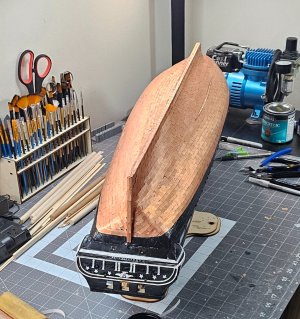
I laid the plates from stern to bow, bottom to top on the starboard side following the practicum. The fillers are somewhat dismissed in the practicum because of the original scale variance that Bob noted in the practic20250810_201248.jpg20250810_201255.jpg20250810_201315.jpgum. If this is the case, then that would likely or possibly hold true for the plates. I found doing a filler only in a couple small areas, although I had expected a lot more. Using the tape, it’s much easier because you can cut and/or overlap to make nice lines. The plates look neater, but do not leave you with nice lines because each plate is placed individually and some might go edge to edge of the plate or slightly overlap the plate. I had the luxury of realizing that the company I bought the plates mixed both sizes which made it challenging. The only way I made it without going insane was to overlap some plates and not overlap some of the plates to prevent any gaps and/or your row of plates from veering off from the right direction.

For the port side, I did it in reverse and started from the top to keel and from the middle and outwards. If my top waterline was taped off, that worked nearly identical in principle the starboard side. Bob uses two taped off areas of tape, but I felt that it was not necessary and more confusing to follow. In the end, it came out good and not perfect like some of the finished builds in the forum. Overall, I am very satisfied because there were may factors involved to consider. The next model will have tape because I learned how to smooth out the tape better, so it did not look wrinkled or mangled. I do not know how any rivet marks on the plates would be affected if you needed to smooth the tape out. I have not seen very much on this aspect from folks that chose copper tape over copper plates. This is my first wooden ship build, so I know it’s not museum quality, whatever that really means, and I will keep it as my trophy for surviving this feat, although I also realized I’m not halfway yet in the build, lol. So far, I am happy and if it looks good that’s all that matters.
 
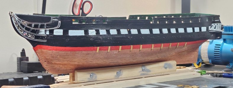
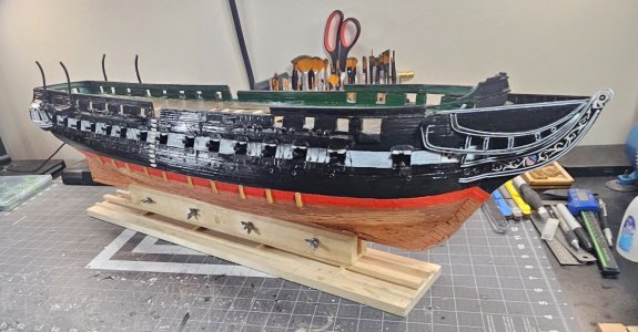
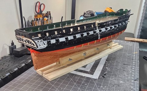
I finally finished Chapter 9 of the Practicum that involved the copper on the hull. This was followed up by painting thr red waterline and then adding the oak timbers on both sides of the hull. After I cut the timbers and beveled them, I used a golden oak stain on them which looks good on the Conny. The polyacrylic does help out a lot and giver her a very clean look and in the light some shine as well. This actually helps blend in any flaws and keeping everything looking somewhat uniform. Tomorrow it'll be time to attack, Chapter 10 of the Practicum.20250811_201118.jpg20250811_202343.jpg20250811_202419.jpg20250811_202423.jpg20250811_202452.jpg
 
I finally finished Chapter 9 of the Practicum that involved the copper on the hull. This was followed up by painting thr red waterline and then adding the oak timbers on both sides of the hull. After I cut the timbers and beveled them, I used a golden oak stain on them which looks good on the Conny. The polyacrylic does help out a lot and giver her a very clean look and in the light some shine as well. This actually helps blend in any flaws and keeping everything looking somewhat uniform. Tomorrow it'll be time to attack, Chapter 10 of the Practicum.View attachment 537475View attachment 537476View attachment 537477View attachment 537478View attachment 537479
Good morning. Wonderful progress. Cheers Grant
 
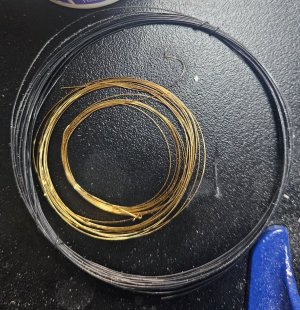
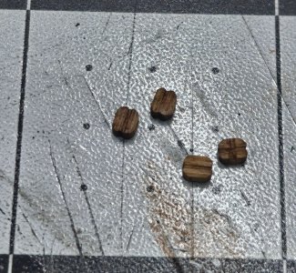
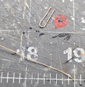
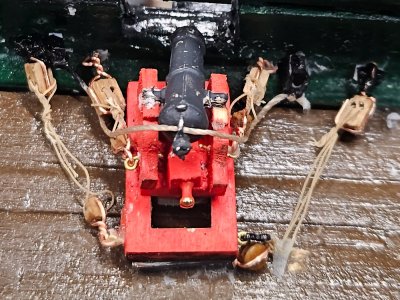
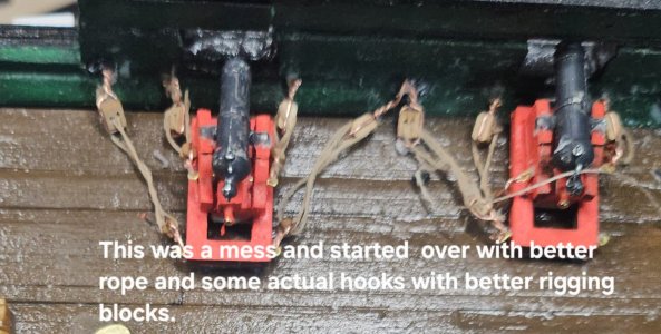
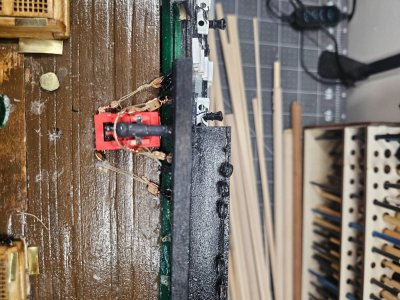
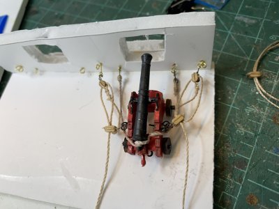
Moving along with the cannons, gunports, and outer hull and deck work. Cannons, curtains, and lower gunport doors were easy to work with, although it felt somewhat time consuming because you are working with 30 gunports. The pain really is dealing with the upper gunports because you have to create a micro miniature rope-like object connecting the upper gunport after you drill 2 holes using a #77 drill bit which is super tiny in itself and very easy to break. I'm on my fourth one now. My kit came with black annealed wire to simulate what would have been rope connected to the upper gun port to its respective top curtain. You definitely want to make sure that hole in the curtain is free and clear because that is one of three areas connecting the door. The two holes you drilled in the gunport door are the other two areas. As much as I enjoy seeing how nicely this is created in the practicum, creating something this tiny and trying to bend the wire into the holes is not so easy and certainly not as perfect in the pictures. In fact, it is so small that you never really see it unless you're right up staring at the gunports near your face. I finished slightly over half of them on the port side and touched up the white paint on the gun port doors as well.
20250815_061746[1].jpg20250815_061753[1].jpg20250815_061759[1].jpg20250815_061838[1].jpg
 
Everyone, my apologies for not releasing my post, somehow, I got sidetracked and forgot the send button. Anyway, here is the latest somewhat...

While I'm working on the channels, deadeyes, and eye chains, etc. There are definitely some things I wish I knew before this part of the build. The practicum seems somewhat incomplete, but I think Bob Hunt expected us to figure this out based on what we've learned thus far throughout the course of the practicum. I read a lot, but if the reading gets very complicated to understand, if you show me a picture what it should look like, it will click in, and I can certainly get it done that way. The ship's plans also get complicated because some things seem to be off or missing altogether.

Most builders can solder well or make a mess doing it. I can for the most part do well because before I became a Navy Officer, I started off Enlisted and flew as an Aircrewman and Rescue Swimmer, but also an Aviation Electrician's Mate. So, we fixed what we flew. Some areas that would have helped before I started, but I'm hoping new assembler/builder would know about this particular Conny kit, so they can make their own decision on what approach they want to take.

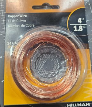
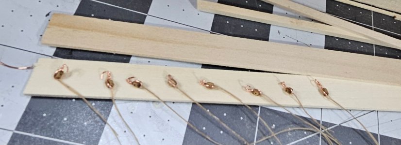
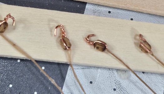
For starters, choosing brass wire for the deadeyes was clearly not a very good idea, particularly the gauge of the wire. The wire does not twist well and breaks very easily. It does not conduct the soldering iron temperature very well and you find yourself taking forever to heat it up, let alone soldering the strip which is also bass. In other words, the choice of this to include in the kit totally sucks and was a poor choice. The wire is kept breaking on me as I tried to twist it onto the eyebolt. Solder does not adhere to brass very well at all, so trying to solder the brass wire around the eyebolt to the brass strip was a complete waste of time. My solution was to get some copper wire that was a slight gauge thicker than the brass. The copper wire was perfectly strong and easier to twist on and keep it there and finish it off with a pair of needle nose pliers to tighten it up against the deadeye and none of them broke. To solder the deadeye to the eyebolt strips, I used my magnifying stand that had clips and arms to hold each piece separately. you can tin each piece before soldering them together, however, tinning the strip being brass was just a waste of time and copper took to it immediately. The easiest way and the fastest way without making a mess and using as little of the surface area was to position the brass strip on top of the deadeye copper wire that was trimmed down to 3/32 and then place the soldering iron needle under the copper wire and use the flux core solder from the top. it would be instantaneous and no waiting to hear up like the brass wire. Doing it this way makes the smallest possible amount of solder to adhere to joining both pieces quickly because the solder immediately goes to the copper wire first and enough to cover it, and the strip of brass gets caught in the melting action and when you remove the soldering iron you'll find that the strip did connect and notice it isn't globby from the solder. This makes it ideal to fit in the grooves you created in the channel.

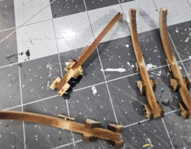
This then leads into the channel portion and the grooves you created for the eyebolts and deadeyes, these need to at least 1/16 wide and deep for the copper wire and strip to sit in the groove comfortably before using the 1/16x1/16strip of wood across the channel over the eyebolts covering the soldered areas and enclose nicely. I recommend getting the eyebolts on the channel, closing it up and then painting them before gluing the channel onto the hull.

Bob had given measurements for each of the eyebolt strips, and I found those as really unnecessary. Everything seemed to be the same distance and more even than making a couple of them vary in length. I also am not sure how those rivets even fit inside the eyebolt because it is just ridiculously tiny, and my hand is certainly not steady to try to go through the strips into the hull. I end up simulating to bolt top with globs of paint, however, even if I used the rivets and survived that ordeal, you can barely notice them unless you have your face up to the hull. It seems a bit unrealistic with .035 rivets to fit in like that. simulating them much easier, but barely noticeable to the naked eye. This is my take on this specific part of the build. I'll include pictures later today of at least one side that was completed. so, preparing the deadeyes and soldering them to the eyebolt strip began as like 2-3 per hour to 10-12 per hour...major difference here.
 
I finally finished Chapter 9 of the Practicum that involved the copper on the hull. This was followed up by painting thr red waterline and then adding the oak timbers on both sides of the hull. After I cut the timbers and beveled them, I used a golden oak stain on them which looks good on the Conny. The polyacrylic does help out a lot and giver her a very clean look and in the light some shine as well. This actually helps blend in any flaws and keeping everything looking somewhat uniform. Tomorrow it'll be time to attack, Chapter 10 of the Practicum.View attachment 537475View attachment 537476View attachment 537477View attachment 537478View attachment 537479
Looking good! You have done a lot of work!
 
Everyone, my apologies for not releasing my post, somehow, I got sidetracked and forgot the send button. Anyway, here is the latest somewhat...

While I'm working on the channels, deadeyes, and eye chains, etc. There are definitely some things I wish I knew before this part of the build. The practicum seems somewhat incomplete, but I think Bob Hunt expected us to figure this out based on what we've learned thus far throughout the course of the practicum. I read a lot, but if the reading gets very complicated to understand, if you show me a picture what it should look like, it will click in, and I can certainly get it done that way. The ship's plans also get complicated because some things seem to be off or missing altogether.

Most builders can solder well or make a mess doing it. I can for the most part do well because before I became a Navy Officer, I started off Enlisted and flew as an Aircrewman and Rescue Swimmer, but also an Aviation Electrician's Mate. So, we fixed what we flew. Some areas that would have helped before I started, but I'm hoping new assembler/builder would know about this particular Conny kit, so they can make their own decision on what approach they want to take.

For starters, choosing brass wire for the deadeyes was clearly not a very good idea, particularly the gauge of the wire. The wire does not twist well and breaks very easily. It does not conduct the soldering iron temperature very well and you find yourself taking forever to heat it up, let alone soldering the strip which is also bass. In other words, the choice of this to include in the kit totally sucks and was a poor choice. The wire is kept breaking on me as I tried to twist it onto the eyebolt. Solder does not adhere to brass very well at all, so trying to solder the brass wire around the eyebolt to the brass strip was a complete waste of time. My solution was to get some copper wire that was a slight gauge thicker than the brass. The copper wire was perfectly strong and easier to twist on and keep it there and finish it off with a pair of needle nose pliers to tighten it up against the deadeye and none of them broke. To solder the deadeye to the eyebolt strips, I used my magnifying stand that had clips and arms to hold each piece separately. you can tin each piece before soldering them together, however, tinning the strip being brass was just a waste of time and copper took to it immediately. The easiest way and the fastest way without making a mess and using as little of the surface area was to position the brass strip on top of the deadeye copper wire that was trimmed down to 3/32 and then place the soldering iron needle under the copper wire and use the flux core solder from the top. it would be instantaneous and no waiting to hear up like the brass wire. Doing it this way makes the smallest possible amount of solder to adhere to joining both pieces quickly because the solder immediately goes to the copper wire first and enough to cover it, and the strip of brass gets caught in the melting action and when you remove the soldering iron you'll find that the strip did connect and notice it isn't globby from the solder. This makes it ideal to fit in the grooves you created in the channel.

This then leads into the channel portion and the grooves you created for the eyebolts and deadeyes, these need to at least 1/16 wide and deep for the copper wire and strip to sit in the groove comfortably before using the 1/16x1/16strip of wood across the channel over the eyebolts covering the soldered areas and enclose nicely. I recommend getting the eyebolts on the channel, closing it up and then painting them before gluing the channel onto the hull.

Bob had given measurements for each of the eyebolt strips, and I found those as really unnecessary. Everything seemed to be the same distance and more even than making a couple of them vary in length. I also am not sure how those rivets even fit inside the eyebolt because it is just ridiculously tiny, and my hand is certainly not steady to try to go through the strips into the hull. I end up simulating to bolt top with globs of paint, however, even if I used the rivets and survived that ordeal, you can barely notice them unless you have your face up to the hull. It seems a bit unrealistic with .035 rivets to fit in like that. simulating them much easier, but barely noticeable to the naked eye. This is my take on this specific part of the build. I'll include pictures later today of at least one side that was completed. so, preparing the deadeyes and soldering them to the eyebolt strip began as like 2-3 per hour to 10-12 per hour...major difference here.
When you are working with brass, you can make it much more malleable if you anneal it by heating it until it is red and letting it cool. Make sure the brass is cleaned of any coating or organic material before you attempt to solder it. I find using silver solder works better than regular rosin core solder.

Rob
 
Back
Top