• Win a Free Custom Engraved Brass Coin!!!
    As a way to introduce our brass coins to the community, we will raffle off a free coin during the month of August. Follow link ABOVE for instructions for entering.

A Katwijk Bomschuit

Update 6
We've made some more progress, so it's time for an update.
To determine where the strakes should end up on the stems, I came up with the following.
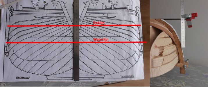
06-01-verloopUitmeten.jpg

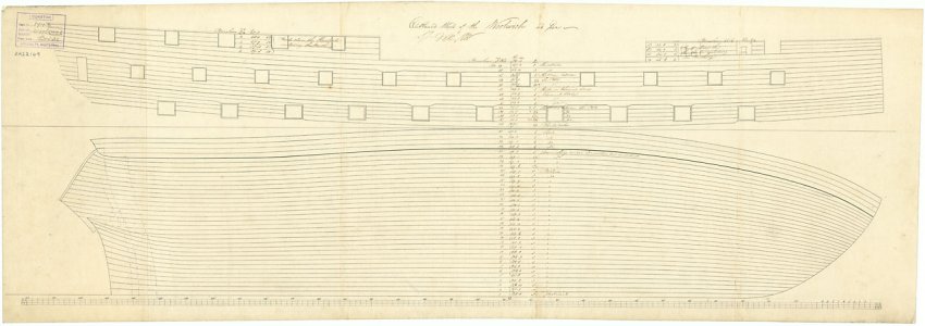
I placed a ruler on the drawing of the bow so that the distances at which the strakes end on the stem can be read from the bottom. This tells me how far above the bottom a particular strake should end.
Then I hung the ruler at that distance on a piece of wood lying on the bottom. The bottom of the ruler then indicates the place where the strakes should end on the stem.
It works, but it's not very convenient. You can put marks on the stem, but at a certain point there are so many marks that you can't tell anymore.

I think a better method is the following:
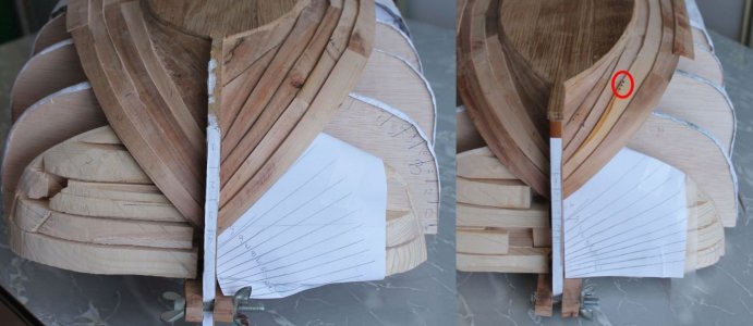
06-02-LijnenVerloop.jpg

The left side is the bow and the right side is the stern.
I copied the lines from the drawing onto a piece of paper that I stuck to the frame. The model lies on top of this, allowing me to apply the lines to the model.

At the stern, you can see three nail heads in the circle. I thought I would apply a series of nails here and there so that I wouldn't have to add a bulk afterwards. That turned out not to be such a good idea, because it meant I had nailed the model to the frame. I was able to pull out three nails, but if there had been a few hundred, it would have been more difficult. So I'll just postpone this until I no longer need the frame.

Now for the current state of affairs.
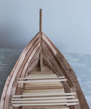
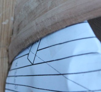
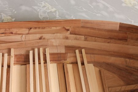
06-03-Boeg-binnen.jpg

The bow seen from the inside. The coming strakes will be very narrow at the stern and much wider towards the middle, creating a fan pattern.
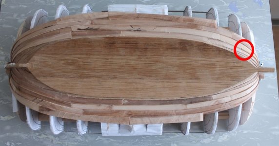
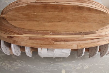
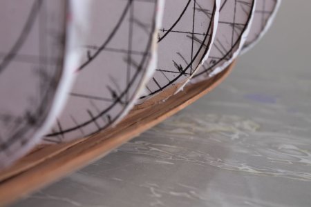
06-04-Bodem.jpg

The model seen from below. The three nails are visible in the circle.
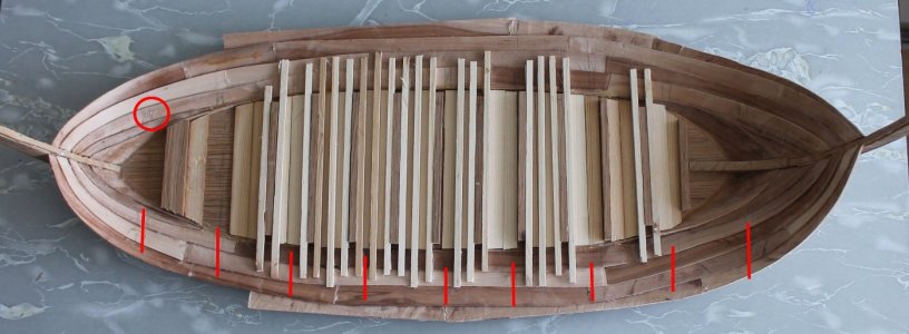
06-05-Bodem-binnen.jpg

The model seen from the inside. Some more wooden pieces have already been added here. Not everything yet, because the frame must be able to stand on the bottom at the location of the red lines. In the circle again, the three nails and exactly on a red line where the frame is located.

To be continued.

Translated with DeepL.com (free version)
 
Update 7

I am now working on installing the sixth row. So I now have some experience with clinker planking. I must say that this is quite different from sealing a “hollander.” And because there are few people here on the forum who have planked a ship clinker-built from scratch, I am sharing my experiences here.

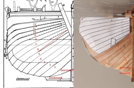
The front view looks like this:

07-1-voor-en-mijn.jpg

Left according to the drawing and right my model.
In the left drawing, I have marked the course of my sixth strake in red. I am too high at the stem and going down too steeply. I think I can still compensate for that by making the planks slightly narrower at the stem and slightly wider at the stern. I still have 6 strakes to compensate for that.
Something else, the sheer.
My model has a slight sheer on the bottom. Compare it with the straight slat that is lying on top of it.

07-2-mijnzeeg.jpg
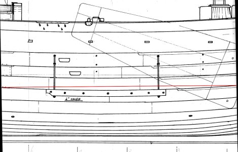
In the drawing, there is also a slight sheer when viewed from the side.

07-3-zij-midden-zeeg.jpg

The sheer can be seen below the red line. The sheer is concave here (lower in the middle than
on the sides). My model is upside down, but if you put it upright, the sheer is convex there (higher in the middle than on the sides).
In the next strakes I will have to work from convex to concave.

Then another mistake.
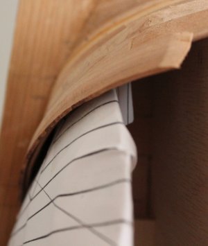
07-4-spleet.jpg4

This is the start of strake 6 at the bow. Here you can clearly see that it does not fit properly against
the mold. forgot to bevel the previous step here.

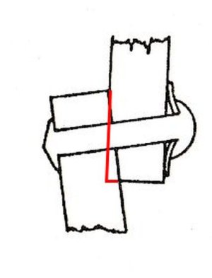
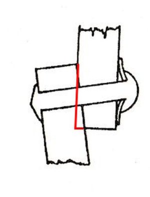
In Petrejus' book (De Bomschuit, een vergeten scheepstype) there is a sketch showing how a rivet is attached, and the
beveling is clearly visible.

07-5-lasmetklink.jpg5

The right plank is slightly beveled lengthwise so that the left plank meets it at an angle. A rivet must then be driven into the overlap. In reality, this is done at a distance of 5 cm. On my model, this is 2.5 mm.

I did the beveling over a distance of 3.5 mm (slightly more than allowed).
07-6-Klinkruimte.jpg

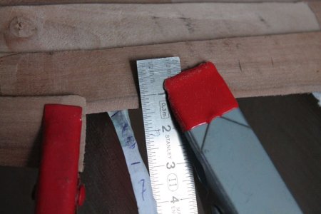
Beveled from 10 to 13.5 mm on the ruler. Later, some nails will have to be applied to that edge.
I reapplied the start of strake 6 after chamfering strake 5 a little.
With this result:

07-7-Afgeschuind2.jpg

That looks a lot more acceptable.

To be continued

Translated with DeepL.com (free version)
 
Stephen,
I agree. You cannot find a straight piece of wood on the whole ship. All sides of it have to be made to fit.
Building from a kit you can sometimes place a batten straight from the kit onto the model.
That is here not possible perhaps, may be, on the deck.
 
Stephen,
You said "What I found the hardest...." Does that mean you have build also a clinker build wooden model?
I don't see it in your list of builds.
Jan
 
And because there are few people here on the forum who have planked a ship clinker-built from scratch, I am sharing my experiences here.
Do you find clinker construction easier or more difficult than carvel construction? My recent experience with the cutter project here at SoS was a mix. Some things I found easier or more forgiving other things more difficult. I love the look of the lapstrake more than the carvel build though :)
Allan
 
You cannot find a straight piece of wood on the whole ship. All sides of it have to be made to fit.
I agree but it is the same with carvel builds as well. If you look at any planking expansion drawing and you not see any straight strakes of planking. Unlike some kit makers that include bundles of straight pieces that are to be used for the planking, the high quality kit makers now seem to be including spiled planks which is a great change.
Allan
1755943380238.jpeg
 
Last edited:
I would like to see a planking expansion drawing of a bomschuit. Do they exist? I think the planks of the bow and stern would spread at the and as the 5 fingers of a hand.
 
It's interesting to read that many find clinker style planking is more difficult as I had assumed (as I'm on my first build and have never done carvel construction) that it would be simpler. That said, I did so completely botch my first attempt, I succumbed to the urge to start over on the project. Also, I think the hull design on my own build is perhaps a simpler shape than this one.
 
Last edited:
I think the planks of the bow and stern would spread at the and as the 5 fingers of a hand.
Hi Jan
Not sure what you mean. If they spread there would be gaps between the planks which obviously cannot be. Planks lap or butt against each other on all vessels form stem to stern post and would look similar, if laid flat, to other planking expansion plans. I have never seen these for other than English ships, but hopefully some member can help on this. I THINK you can create your own using CAD if you have the body plan. Again, hopefully a member who is proficient in CAD can confirm or correct that idea.

Allan
 
Stephen,
You said "What I found the hardest...." Does that mean you have build also a clinker build wooden model?
I don't see it in your list of builds.
Jan
Hi Jan,
The work boat is for my Drifter Trawler and is clinker built and is included in that build thread on the first page of the build. I built it a long time before I started photographing progress when I am building this means there are not many photos of the construction process, just some notes from memory.

Cheers,
Stephen.
 
Last edited:
Hi Jan
Not sure what you mean. If they spread there would be gaps between the planks which obviously cannot be. Planks lap or butt against each other on all vessels form stem to stern post and would look similar, if laid flat, to other planking expansion plans. I have never seen these for other than English ships, but hopefully some member can help on this. I THINK you can create your own using CAD if you have the body plan. Again, hopefully a member who is proficient in CAD can confirm or correct that idea.

Allan
Hi Allan,
Jan, I hope you don't mind me jumping in on this answer.
I think what Jan is referring to is the width of material needed to manufacture the plank especially at the point of greatest curvature.

Cheers,
Stephen.
 
Hi Jan,

What I do to determine the shape of a plank is to stretch a strake of paper on top of the previous plank in the position of the plank you want to make, then with your vingernails press the edge of the plank in the paper. If you then remove the paper and cut along the imprint you have the shape of the next adjacent plank.
 
Maarten,
Yes, this is the way it is done in real. One placed a new plank against the former one en with a crayon marks the outline of the former plank on the new one. The the new plank is sawn a few cm from the crayon line.
This method, also like yours, is possible when you work from inside. I work from outside.
When working from inside the edge of the last plank has to be a nice shape, giving that shape to the new plank. But that shape later wil disappear behind the innerplanking.
When working from the outside I focus me on a smooth lower line of the new plank. This stays visible. The top line of the new plank will, on the outside, be hidden by the following plank and on the inside by the inner planking. So I don't bother me of that line. And when you look to that lines inside, you see that they are very ugly, and therefore not useful for your method.

07-SOS-quetionMaarten.jpg

It was never my intention to build a bomschuit using the historical correct buidling method. I want to build a bomschuit including the innerside showing how it is used by fishing on herring and showing how people live and works on it. This ugly innerside later will be hidden behind a nice looking innerplanking and in the bow by some beds for the crew to sleep.

I suppose it is another way of building then your build of the "Zwaan ("the ghost ship"), Dutch fluyt reconstruction of mid 1600's" where you try to show the original way of building.
 
This is spiling which means strip wood that many kits supply is of no use. There is a great little article on spiling by David Antscherl. Alternatively the shape taken on the paper can be transferred to a scrap piece of wood and then cut out to use as a former to edge bend the plank without it lifting. I like this method almost as well as spiling, using soaked strakes, then once clamped around the forming piece, dry it with a hot air gun and it will hold its shape.

Allan

Spiling https://www.sdshipmodelersguild.org/documents/presentations/APrimerOnPlanking.pdf
Four part video for edge bending
 
Update 8
I'm making a bit of a mistake.

08-1-gap.jpg

As you can see in this photo, the last plank no longer touches the bulkheads. And that's not because the bulkheads aren't aligned, because they are.
So what is the reason?
Now I remember experiencing something similar when planking the Kamper cogs, but to a lesser extent. I couldn't figure out the cause at the time, but now I think I know.
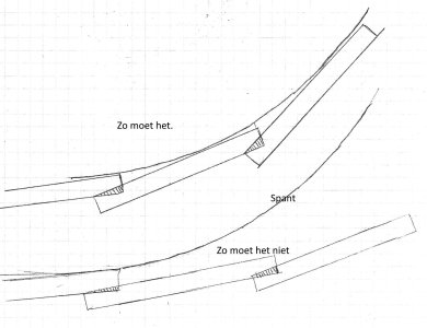
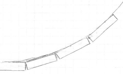
In update 7, I showed that when the planks overlap, one of them has to be bevelled. This means that the planks are not exactly parallel, but at a slight angle.

08-2-lasmetklink.jpg


08-3-vergelijking.jpg

It turns out that it cannot just be any angle, but an angle that allows the new plank to follow the curve of the frame.
In my case, the angle was apparently too slight, causing the plank to run away from the frame.
My club mates at the bomschuitenclub have already built several bomschuiten and never had this problem. How is that possible?
Well, they always built the boat with bulkheads. This means that the planks were not attached to each other but to the bulkheads. If you don't bevel them enough, you end up with a gap. Well, you can fill that gap with something.

Why don't you have this problem when you build smooth-sided boats?
08-4-Karveel.jpg

Well, you always build against the bulkheads and you have to bevel the sides of a batten slightly to avoid gaps.


Now for the solution for my problem.
I see two options.

1. Loosen a number of planks, chamfer them correctly, and glue them back in place.
2. Temporarily secure them to the bulkheads with a nail and continue. The next plank should then hold everything in place.
Option 1 is the best if it works, but option 2 is the fastest.
I want to go for option 1, but first I will try option 2 to see if that works.

08-5-Zij-BB-lat.jpg
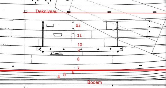
In the middle, the skin is attached to the bulkheads with a nail. But it is clear to see that the plank curves upwards there. By pressing that plank (which in the old situation had a nice smooth curve) upwards with a nail, it now forms a bubble, whereas it should actually have a slight camber, as can be clearly seen in the drawing below. The thick red line above the sixth line is straight. Plank 6 protrudes above it at the ends.

08-6-Zijkant.jpg
Plank no. 6 shows a slight camber here, but the model shows a bulge.

Option 2 does not work, so it will be option 1.
To be continued.

Translated with DeepL.com (free version)
 
Jan, I feel your pain. The same thing happened on my build about 8 months ago. I tried fixing the mistake, but by that point I had racked up so many mistakes, I scrapped the whole build and started over.

I did something similar to option 2 and it distorted the intended hull shape. I think option 1 will work much better for you.
 
Back
Top