ThanksThanks for the heads up Tim, I appreciate it ! Your build looks great ! Keep it up !
-

Win a Free Custom Engraved Brass Coin!!!
As a way to introduce our brass coins to the community, we will raffle off a free coin during the month of August. Follow link ABOVE for instructions for entering.
-

PRE-ORDER SHIPS IN SCALE TODAY!
The beloved Ships in Scale Magazine is back and charting a new course for 2026!
Discover new skills, new techniques, and new inspirations in every issue.
NOTE THAT OUR FIRST ISSUE WILL BE JAN/FEB 2026
- Home
- Forums
- Ships of Scale Group Builds and Projects
- Modelship Dockyard PoF HMS Enterprize 1774 - 1/48
You are using an out of date browser. It may not display this or other websites correctly.
You should upgrade or use an alternative browser.
You should upgrade or use an alternative browser.
Correct. Everything, so far, is only dry fit while finalizing dimensions, locating on beams, etc.Tim,
VERY NEAT WORK!!
Is the well and shot locker in your photo just resting where it is and not yet fixed in their final location?
Thanks
Allan
Once I get all compartments done and get a couple coats of finish below platforms, will start to glue up structures.
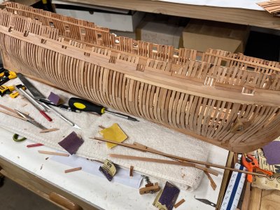
Now, working on 3-4 courses of exterior planking around gun ports to get dimensions correct and give extra strength to framing, etc.
As noted earlier, have had to rip replacement planking in some locations, especially the small angled sections between ports. Seems like they are all short as supplied and zero work around except to fab new ones. As I indicated, however, there is plenty of extra material remaining on sheets with all framing removed to rip new planks and allow wood to match fairly well......folks, don't throw anything away!
Tim
Just, added. Not really any sanding done yet but planks lay on frames nicely and edges seem tight to adjacent run so I think I’ll be all right.
Some color variance between the 5-6 sheets but that will even out with selective coats of finish when ready.
Last edited:
She is looking beautiful, Tim ! Great work !
I have to take a short break from my build because I have a friend that broke their wood bed frame and I said I would fix it for them.
Shouldn't take me more than a week...
I have to take a short break from my build because I have a friend that broke their wood bed frame and I said I would fix it for them.
Shouldn't take me more than a week...
Kurt Konrath
Kurt Konrath
Don't ask what they were doing when they broke the wood bed frame!She is looking beautiful, Tim ! Great work !
I have to take a short break from my build because I have a friend that broke their wood bed frame and I said I would fix it for them.
Shouldn't take me more than a week...

Jeff, all,
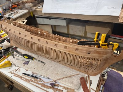
Although I did not intend too, pushing along with the exterior planking which is moving along and after initial light sanding seems to be OK. Still have to trim/square up planking that covers a couple ports.
Probably do the double layer Wales before I go back to interior construction. Pays to mix it up somewhat IMHO.
Tim

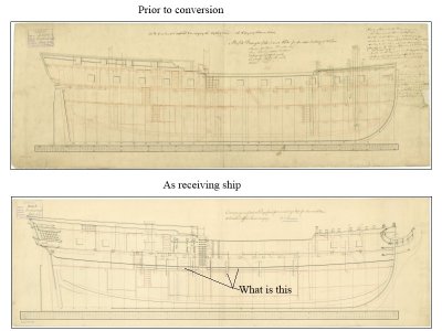
I have a question regarding Enterprise as a receiving ship hulk when she had no masts, wheel, guns, etc. as she was set up as one for more years than she was a fighting ship. What are the parts marked on the drawing below? I am guessing the vertical pieces could be knees, but what was the purpose of these parts?
Thanks
Allan
Thanks
Allan

Purely a guess on my part, but I would imagine that they cut out a large hole in lower deck to make the hold more available and they did that for additional structural bracing that the deck and beams used to provide. Again, totally just a guess on my part !I have a question regarding Enterprise as a receiving ship hulk when she had no masts, wheel, guns, etc. as she was set up as one for more years than she was a fighting ship. What are the parts marked on the drawing below? I am guessing the vertical pieces could be knees, but what was the purpose of these parts?
Thanks
Allan
View attachment 547168
Makes some sense to me, but why not hammocks? This is getting more interesting than I thought it would be.altered the horizontal structures, particularly on that deck, may have been platforms for sleeping for all the “ residents” .
Allan
- Joined
- Jul 24, 2016
- Messages
- 540
- Points
- 188

can you measure the depth from the bottom of the frame where it rests on the bench to the bottom of the keel false keel please
it looks like 10 mm - trying to get a fix on how high each frame is
looking good
You seem to be getting the same problem as i did snapping joints
it looks like 10 mm - trying to get a fix on how high each frame is
looking good
You seem to be getting the same problem as i did snapping joints
- Joined
- Jul 24, 2016
- Messages
- 540
- Points
- 188

i have decided to build 3mm fillers at the top of each frame where it comes through the stand and also near the topLike I continue to tell folks… You can NEVER have enough clamps
It really is strengthening it all uip
Well, if I were to guess…only a guess, I’d guess, for prisoners hammocks would be more expensive and fit fewer “guests”.Makes some sense to me, but why not hammocks? This is getting more interesting than I thought it would be.
Allan
- Joined
- Jul 24, 2016
- Messages
- 540
- Points
- 188

not sure where ther hammocks has come fromWell, if I were to guess…only a guess, I’d guess, for prisoners hammocks would be more expensive and fit fewer “guests”.
- Joined
- Jul 24, 2016
- Messages
- 540
- Points
- 188

Really feel as though I am getting some where I
I HAD thought i gad completed all the Main Frames And Bow and Stern Frames
I did not trim the Thick FRame aft of the Gun Port
However Gun POrt 7 is to close inless you shape Frame 22
Looking at Port 5 Ive shaped 14 and while it was out Cut the angle for the top of Frame
That was good so removed the otherside and cut that
REplace and reglued
One thnh i struggled with was measuring the top of the frames as my calipre is not long enough
Marked 8mm below the keel out it right for measuring
How ever with a few key measurement i am marking the actual Top of Jig and measuring from there
Looking good
Last edited:
- Joined
- Jul 24, 2016
- Messages
- 540
- Points
- 188

Sent to Victor
I think it might be worth makingan update to your instructions
Could you please mark the Top of the Jig on the ,main Full size plan it would make Marking and Cutting the Gun Ports and then top Frames much easier
Also we all seem to e dry fitting the all frames before Fixing them in
I believe it would be much easier to Mark and then cut the Ports before Gluing them into the Keel ie Remove the 3 Frames after Marking them.
Each batch of 3 Frames would then be easier to cut (With possibly a mini Jig on future Models)
This really is an amazing model Light Years ahead of the New European Kits
Although ive not seen the new Vanguard Model of HMS Surprise
Congratulations to the whole Team
ADUM
Just seen Arbons most recent post He has gone very quiet BUT
As he constructors the hull in the Jog he is cutting the Gun POrts and fitting = Make it look so easy !
Last edited:
And it was not possible to post that in your own build-log, Richard? It’s your request related to your workaround, not from Jeff. And this is the log of Jeff’s build.Sent to Victor
I think it might be worth makingan update to your instructions
Could you please mark the Top of the Jig on the ,main Full size plan it would make Marking and Cutting the Gun Ports and then top Frames much easier
Also we all seem to e dry fitting the all frames before Fixing them in
I believe it would be much easier to Mark and then cut the Ports before Gluing them into the Keel ie Remove the 3 Frames after Marking them.
Each batch of 3 Frames would then be easier to cut (With possibly a mini Jig on future Models)
This really is an amazing model Light Years ahead of the New European Kits
Although ive not seen the new Vanguard Model of HMS Surprise
Congratulations to the whole Team
Regards, Peter
Last edited:
- Joined
- Jul 24, 2016
- Messages
- 540
- Points
- 188

Sorry I have upgraded to Windows 11 Its totally different Thought i was in my Post and it is relevant to Jeff as he is working on the same sectionAnd it was not possible to post that in your own build-log, Richard? It’s your request related to your workaround, not from Jeff. And this is the log of Jeff’s build.
Regards, Peter
Last edited:
Allan, hello! What you're asking about are bumpers, or, in other words, fenders. These reinforced fenders were installed on all ships and vessels intended for port service. Ports are crowded, and ships often collide. Often such ships are placed close to each other, and in high waves in bad weather they hit each other hard.What are the parts marked on the drawing below? I am guessing the vertical pieces could be knees, but what was the purpose of these parts?

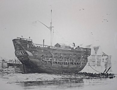
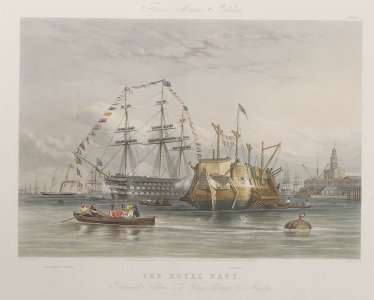
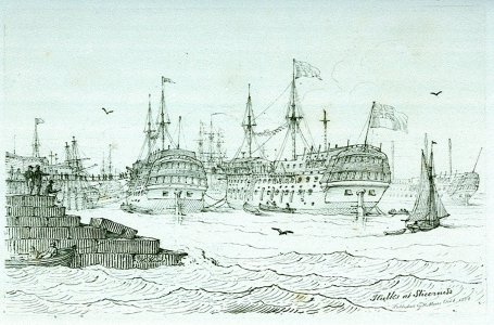

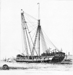
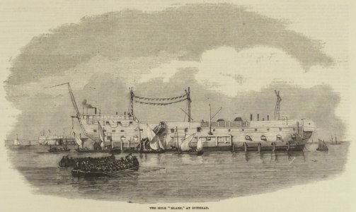
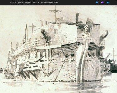

Thanks uitar. Very interesting. I've seen hundreds of naval pictures, but I hadn't noticed anything like these before.Allan, hello! What you're asking about are bumpers, or, in other words, fenders. These reinforced fenders were installed on all ships and vessels intended for port service. Ports are crowded, and ships often collide. Often such ships are placed close to each other, and in high waves in bad weather they hit each other hard.
View attachment 548807
View attachment 548808 View attachment 548809 View attachment 548810 View attachment 548811 View attachment 548812 View attachment 548813
View attachment 548814 View attachment 548815


