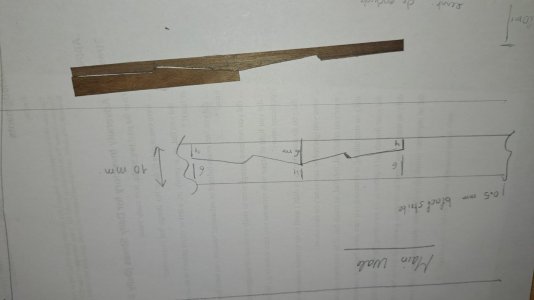
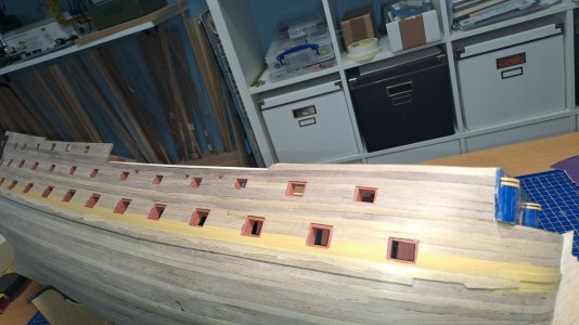
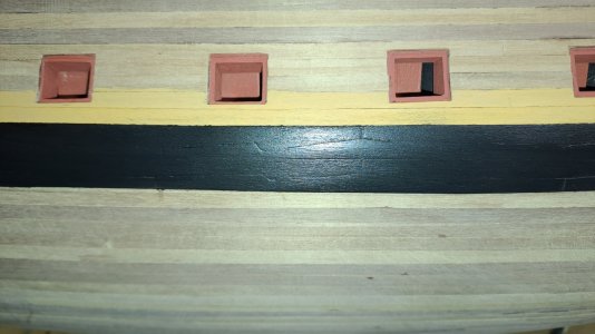
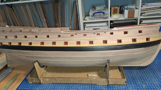
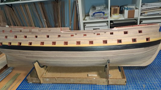
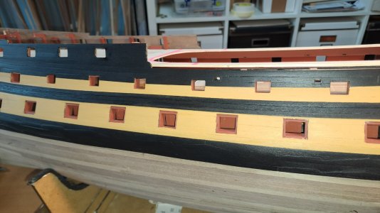
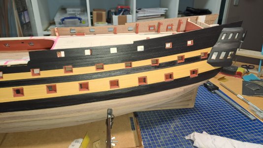
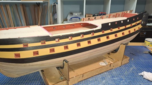
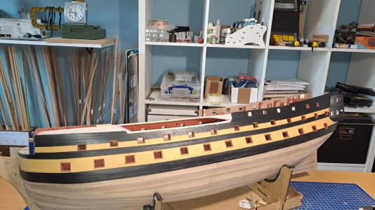
Yes, because then I'm sure to have excact the same dimension...Do you only use one template for every porthole?
View attachment 548473
-

Win a Free Custom Engraved Brass Coin!!!
As a way to introduce our brass coins to the community, we will raffle off a free coin during the month of August. Follow link ABOVE for instructions for entering.
-

PRE-ORDER SHIPS IN SCALE TODAY!
The beloved Ships in Scale Magazine is back and charting a new course for 2026!
Discover new skills, new techniques, and new inspirations in every issue.
NOTE THAT OUR FIRST ISSUE WILL BE JAN/FEB 2026
You are using an out of date browser. It may not display this or other websites correctly.
You should upgrade or use an alternative browser.
You should upgrade or use an alternative browser.
HMS Agamemnon by Caldercraft
- Thread starter HMSFly
- Start date
- Watchers 33
-
- Tags
- agamemnon caldercraft
- Joined
- Jul 24, 2016
- Messages
- 540
- Points
- 188

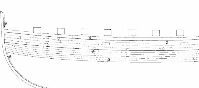
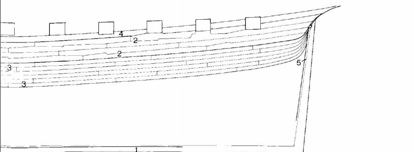
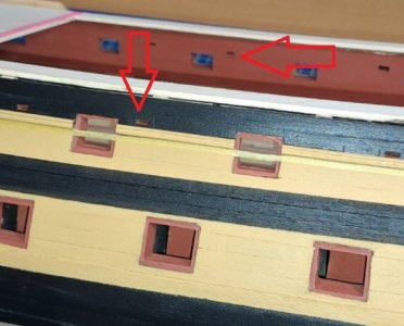
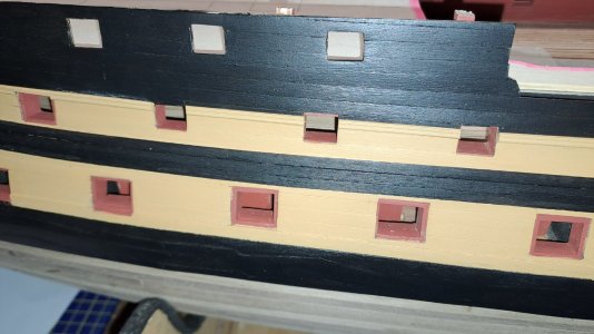
The port holes edges (surrounds) should be covered to their edge by the plankingDo you only use one template for every porthole?
View attachment 548473
Too late now but for next time
uIf ats a double planked model Plank straight under the Gun Port And then fill the gap above and below with 2 timbers
ie use the gunport surround to act as template to cut too
Mosr ports are the same size - look on the plan
Looking good otherwise
- Joined
- Jul 24, 2016
- Messages
- 540
- Points
- 188

Just look at how grey those deck planks arei recon you could 3d print buckets with GR logo
And how thin the Belay Pins are
Yes Iutar, I noticed that already...but It's not wrong neither and looks good after painting the main wale...Not at all
The belts were not supposed to be repeated, and they were not mirrored, and the joints were not supposed to match...
View attachment 548478 View attachment 548479
Not sure exactly what you are referring to.he port holes edges (surrounds) should be covered to their edge by the planking
Allan
Last edited:
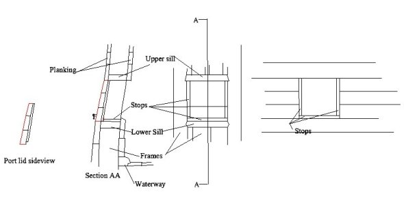
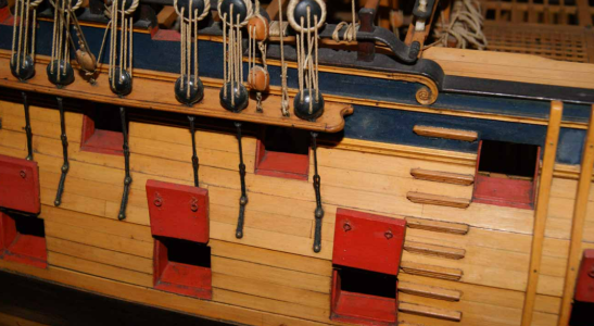
Not sure exactly what you are referring to.The photos above do show the planking ending at the edges of the ports. The planking covers the sill on top and sill on the bottom as well as the frame on each side that make up the port. It does not cover the stops which are recessed and were about 1.5 inches thick. On Marc's model I believe the red pieces are the stops as they are recessed. These were found on the top of the lower sill and on the two sides, but there was no stop on the bottom of the upper sill. The internal planking covers the sills and frames as well as the stops as they extend to the edge of the sills and frames. rather than being recessed on the inboard side.
Allan
View attachment 548506
Hi Richard,Mosr ports are the same size - look on the plan
Looking at the contemporary contract for HMS Nassau, a sister of HMS Agamemnon, the sizes of the gun ports on a given deck are different than the others as the caliber of the guns is different. In addition, while the sides and top and bottom on a given deck are the same, the shape changes as they are parallelograms. Each is a slightly different shape as the angle of the top and bottom of the port changes so they are pretty much parallel to the sheer of the deck.
Allan
From the contract you can see the sizes vary in both depth and fore and aft.
Gun deck 2 feet 8 inches deep and 3 feet 4 inches fore and aft

Upper deck 2 feet 8 inches deep and 2 feet 10 inches fore and aft

Quarter deck 2 feet 4 inches deep and 2 feet 6 inches fore and aft.

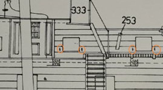
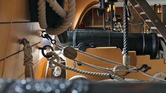
Another oddity: For some reason, the gun ports have two eyebolts each. There should actually be four!
The lower eye bolt must have a ring.
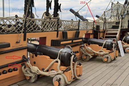
The fife rail for the belaying pin should be installed much lower. The top edge of the gun port serves as a reference point.
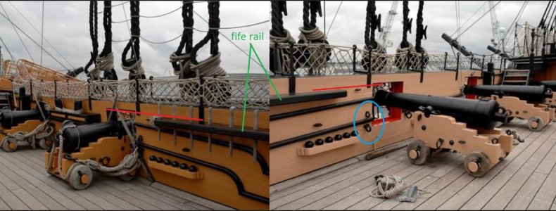
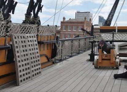
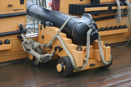
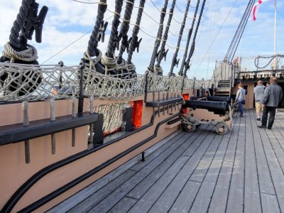
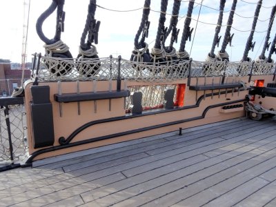
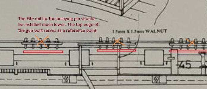
Fife-rails is not a typo, the fife-rails is so named because of its resemblance to a shepherd's pipe, that is, a pipe with a row of holes, this pipe was called a fife.
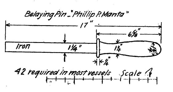
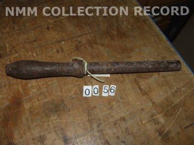
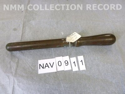
The number of belaying pins should be 12-13 per quarterdeck bulwark. See Longridge for details.
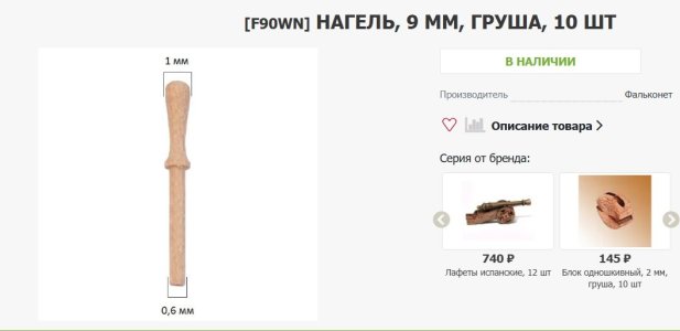
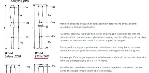
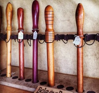
The belaying pins that came with the kit are no good; they should be thrown out. Many companies now sell high-quality replica belaying pins, and I'm sure they're easy to find in Belgium, too. It's best to get bronze ones, then paint them to look like wood—they won't break under the rigging.
The lower eye bolt must have a ring.


The fife rail for the belaying pin should be installed much lower. The top edge of the gun port serves as a reference point.


Fife-rails is not a typo, the fife-rails is so named because of its resemblance to a shepherd's pipe, that is, a pipe with a row of holes, this pipe was called a fife.
The number of belaying pins should be 12-13 per quarterdeck bulwark. See Longridge for details.
The belaying pins that came with the kit are no good; they should be thrown out. Many companies now sell high-quality replica belaying pins, and I'm sure they're easy to find in Belgium, too. It's best to get bronze ones, then paint them to look like wood—they won't break under the rigging.


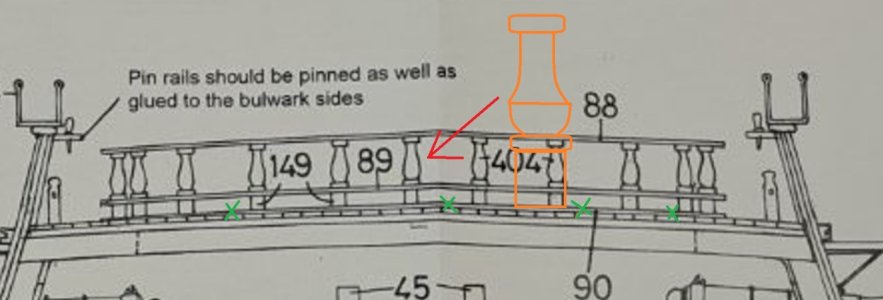
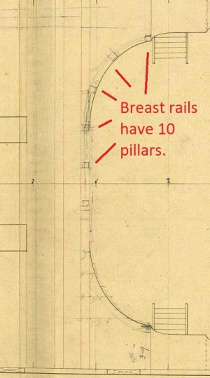
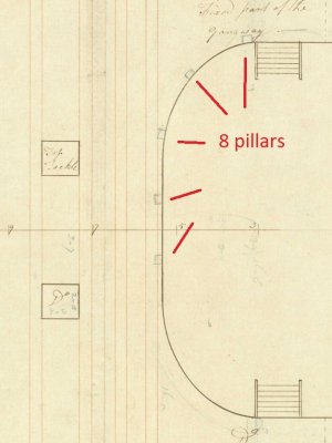
Let's return to the forward quarterdeck beam. The railing installed on it is called a breast rail. Breast rails have either 8 or 10 pillars. Different drawings show this differently. HMS Augusta has 10 pillars. A museum model of an unknown 64-gun ship and a drawing of HMS Nassau show 8 pillars.
The bottom backing (item 90) needs to be removed. At this point there should be a bare forward quarterdeck beam.
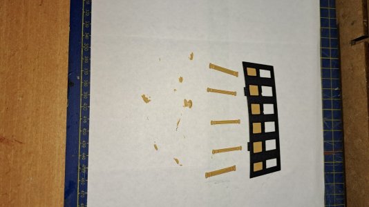
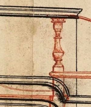
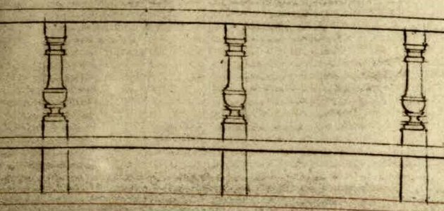
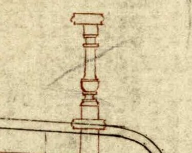
Each pillar (item 404+149) has a different shape than the one in the set. At that time, all decorative pillars were shaped like antique lamps.
The bottom backing (item 90) needs to be removed. At this point there should be a bare forward quarterdeck beam.
Each pillar (item 404+149) has a different shape than the one in the set. At that time, all decorative pillars were shaped like antique lamps.


Last edited:
Thx Iutar!Another oddity: For some reason, the gun ports have two eyebolts each. There should actually be four!
The lower eye bolt must have a ring.
View attachment 548726
View attachment 548727
View attachment 548728
The fife rail for the belaying pin should be installed much lower. The top edge of the gun port serves as a reference point.
View attachment 548729
View attachment 548737
View attachment 548738
View attachment 548739
View attachment 548740
View attachment 548730
Fife-rails is not a typo, the fife-rails is so named because of its resemblance to a shepherd's pipe, that is, a pipe with a row of holes, this pipe was called a fife.
The number of belaying pins should be 12-13 per quarterdeck bulwark. See Longridge for details.
The belaying pins that came with the kit are no good; they should be thrown out. Many companies now sell high-quality replica belaying pins, and I'm sure they're easy to find in Belgium, too. It's best to get bronze ones, then paint them to look like wood—they won't break under the rigging.
View attachment 548733
View attachment 548735
View attachment 548736
View attachment 548741
View attachment 548742
View attachment 548743
Mark, that's good. So, you've set the prototype's time period to the battle with two French frigates on June 1, 1796.

I'm concerned about whether you've done the fitting and calculations as described in post 281. You might need to raise the cutwater (knee of the head) higher, but I hope this problem can be solved without major modifications...
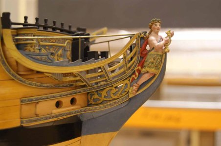
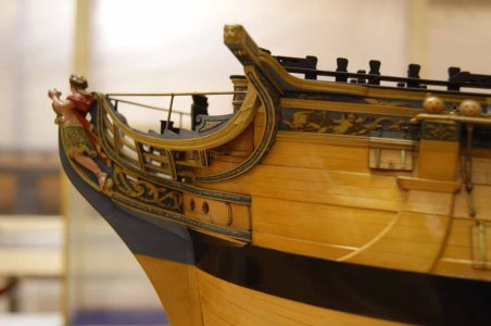
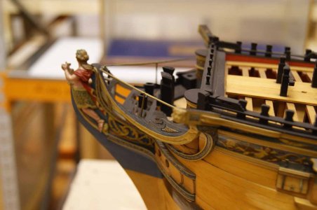
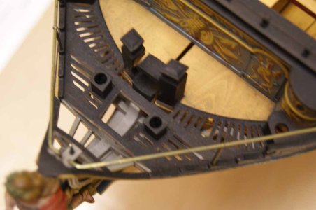
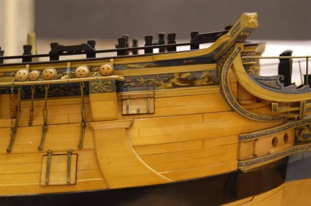
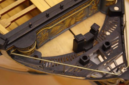
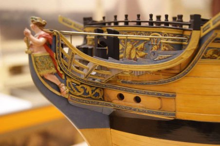
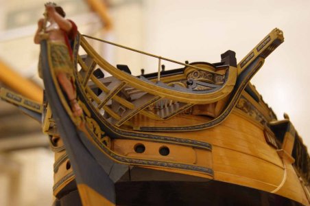
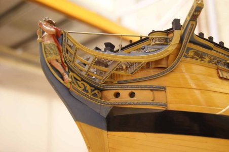
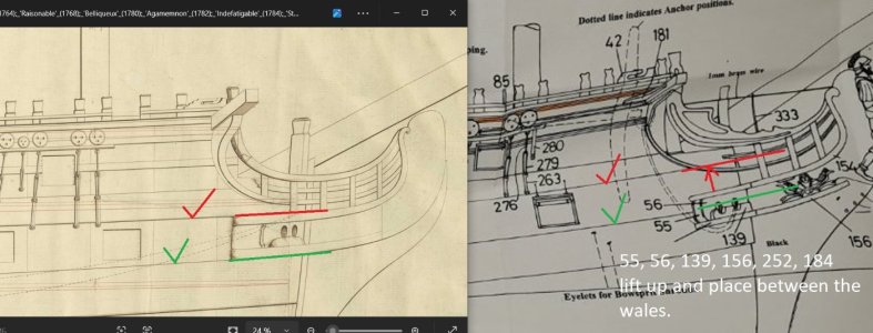
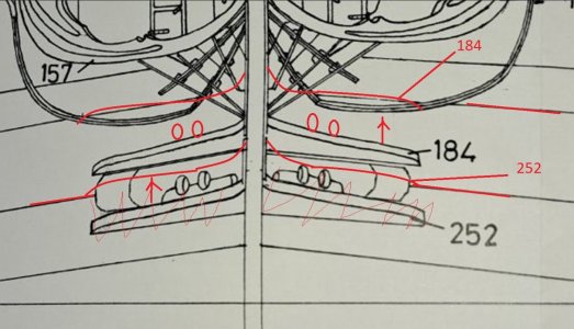
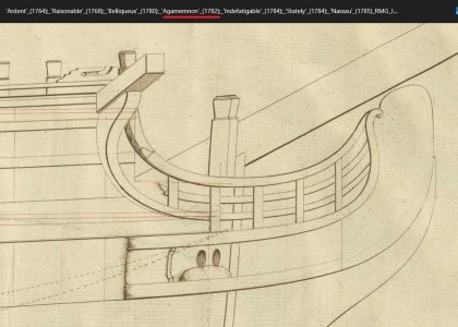

I'm concerned about whether you've done the fitting and calculations as described in post 281. You might need to raise the cutwater (knee of the head) higher, but I hope this problem can be solved without major modifications...


Last edited:
Hey Iutar,Mark, that's good. So, you've set the prototype's time period to the battle with two French frigates on June 1, 1796.
View attachment 549179
I'm concerned about whether you've done the fitting and calculations as described in post 281. You might need to raise the cutwater higher, but I hope this problem can be solved without major modifications...
View attachment 549180 View attachment 549181 View attachment 549182 View attachment 549183 View attachment 549185 View attachment 549188 View attachment 549187 View attachment 549186 View attachment 549184 View attachment 549189 View attachment 549190 View attachment 549191
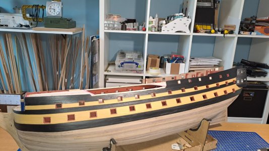
Yes I've got a look on this item.
Either way, it will require some tinkering...but that's for later...
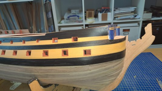
Next step : installation of the decorative strips.
But again a Caldercraft story ...
Caldercraft delivered " Casted strips"....each strip +- 80 mm long....
Not only poorly finished, but no... for such an expensive kit, I find this unacceptable (just my opinion, of course).
So, the solution: 1 x 3 mm walnut strip and make the moldings myself. Much nicer and more finished...
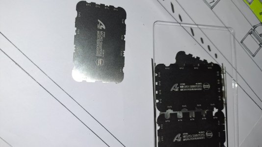
For this, I used Micro Shapers from Artesania Latina...
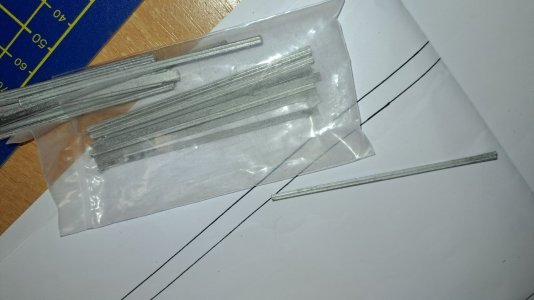
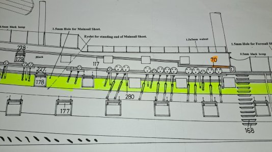
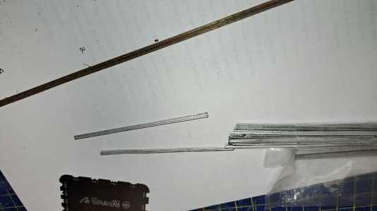
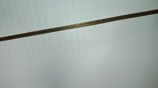
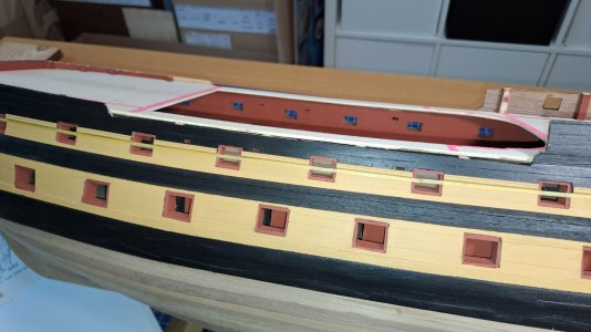
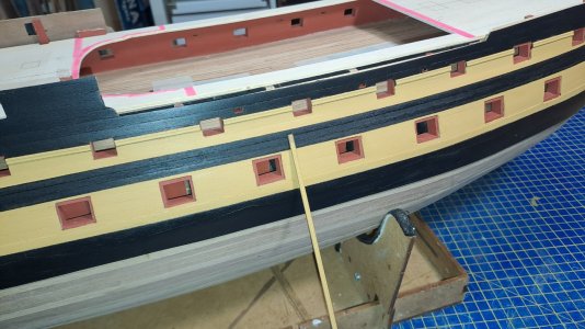
But again a Caldercraft story ...

Caldercraft delivered " Casted strips"....each strip +- 80 mm long....
Not only poorly finished, but no... for such an expensive kit, I find this unacceptable (just my opinion, of course).
So, the solution: 1 x 3 mm walnut strip and make the moldings myself. Much nicer and more finished...
For this, I used Micro Shapers from Artesania Latina...


Wel done Mark, You are on a good way to strart your next project : building ships models from scratch ...

