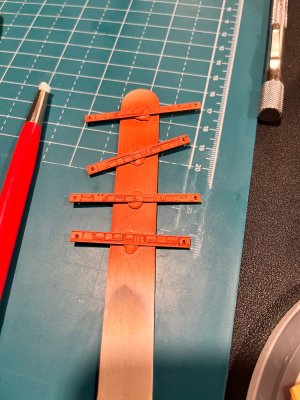
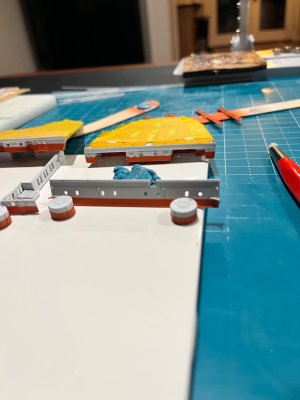
• SUBSCRIBE TO SHIPS IN SCALE TODAY!

    The beloved Ships in Scale Magazine is back and charting a new course for 2026!
    Discover new skills, new techniques, and new inspirations in every issue.

    NOTE THAT OUR NEXT ISSUE WILL BE July/August 2026
  • Win a Free Custom Engraved Brass Coin!!!
    As a way to introduce our brass coins to the community, we will raffle off a free coin during the month of August. Follow link ABOVE for instructions for entering.

RMS Titanic minicraft 1:350 Scale

Hello everybody Again :)

As promised I will discuss my odyssey with the propeller wings and the bilge keels on this post.

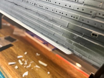
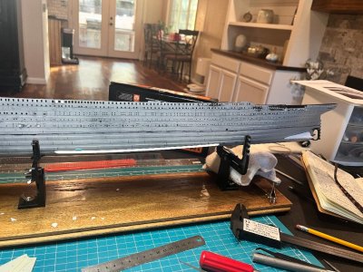
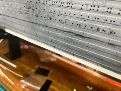
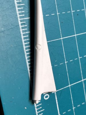
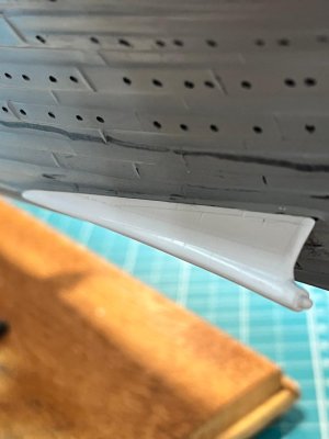
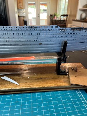
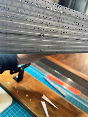
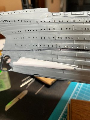
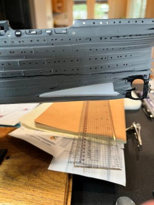
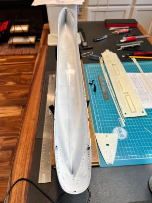
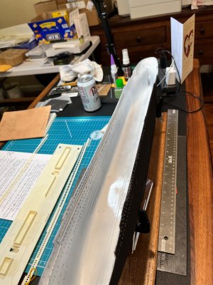
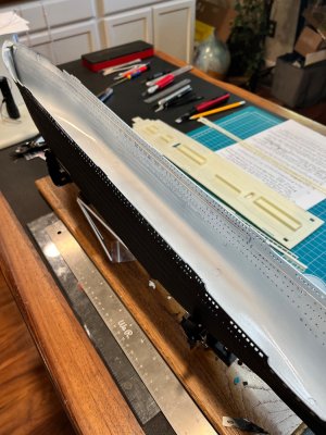
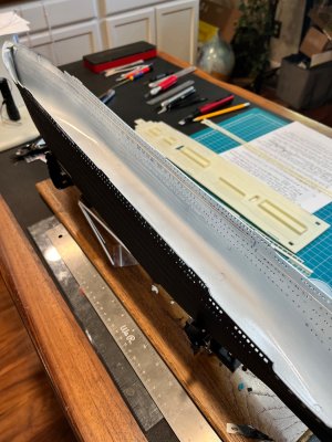
The triangular piece of plastic kit parts F1L and F1R marked as bilge keels are lacking in scale and details as you can see dry fitted to the hull

Bilge Keel 1.jpg

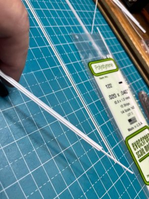
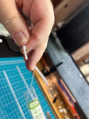
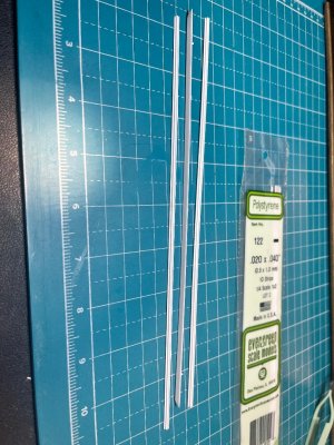
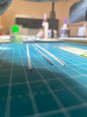
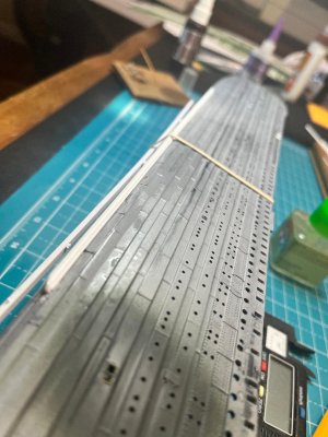
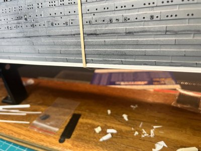
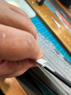
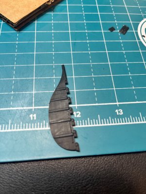
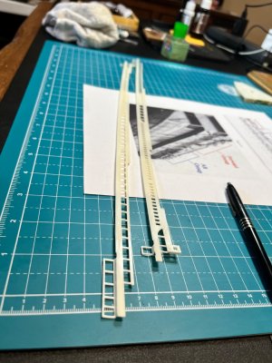
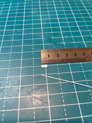
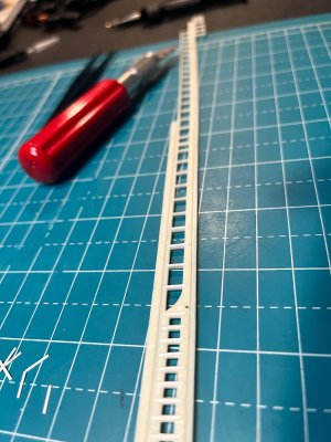
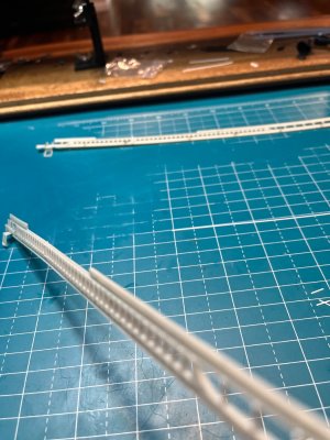
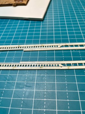
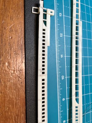
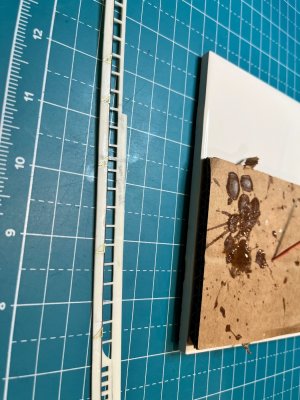
I found the bilge keel plans on encyclopedia Titanic website and found it was made in a layered fashion with a Tee beam and two L beams on each side (over simplified explanation). The dimensions from the plans converted to 1:350 scale are length 26 cm by base width 2.6 mm by height 2.6 mm. So I brought a packet of Plastisteel Tee bar that was 2.5 mm base and 2.5 mm height, and 0.5 mm thickness. Perfect! I added a 0.25 mm by 0.5 mm strip of styrene to the ends and voila. It was not feasible to find 0.25 mm thick L bar styrene. So I used 1 mm by 0.5 mm strips sanded to 0.25 mm for each side of the upright on the T.

Bilge Keel 8.jpg
Bilge Keel 7.jpgBilge Keel 9.jpgBilge Keel 6.jpg

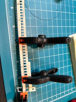
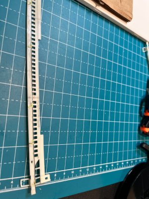
Now cut the the new keel to length and dry fit it to the hull.
Bilge Keel 10.jpgBilge Keel 11.jpg

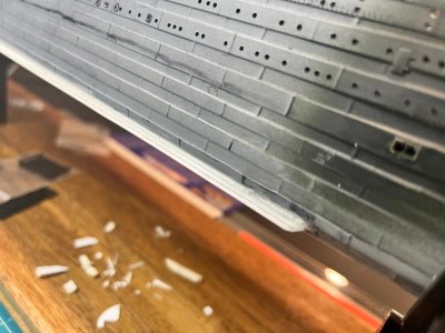
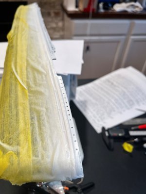
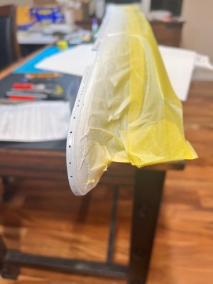
I needed to have a natural curve to the keel following the hull keel mount. I sanded and used putty to make the keel as “riveted” cleanly to the hull. Next time I install this type of part to a hull I will use epoxy glue. I tried a combination of CA glue with ultra thin liquid cement, but found that it could crack with little effort. I finally got enough liquid cement to cure.

Once I had the keel installed I blended the final product into the hull, trying not to remove any of the platting details.

The Propellers will be in the next posts
Happy Modeling- Pete

Bilge Keel 2.jpg

Bilge Keel 3.jpg

Bilge Keel 4.jpg

Bilge Keel 5.jpg
 
Last edited:
Have you seen the absolutely fantastic videos about R.M.S. Titanic on YouTube by Oceanliner Designs?
Type in the YouTube Search bar 'oceanliner designs titanic'. All sorts of in-depth videos on her design and operation.
Cheers
 
Have you seen the absolutely fantastic videos about R.M.S. Titanic on YouTube by Oceanliner Designs?
Type in the YouTube Search bar 'oceanliner designs titanic'. All sorts of in-depth videos on her design and operation.
Cheers
Yes I love that website and visit often
Same with https://www.moddb.com/mods/mafia-titanic-mod/images and Vasilije Ristovic facebook images of the Titanic.

I like the Oceanliner Designs and Titanic Honor and Glory because you can move around to those awkward places. But of course I verify with other sources. However, if I have nothing, then the videos rule because just looking at Vasilije's work and the research he puts into his images makes me feel confident that I have the latest knowledge on the Titanic ( Such as green winches and deck details when we always use to think it was just flat black).
 
Good Day Modelers,

The propeller wings as promised

Propellers Wings 7.jpgPropellers Wings 8.jpg

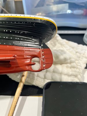
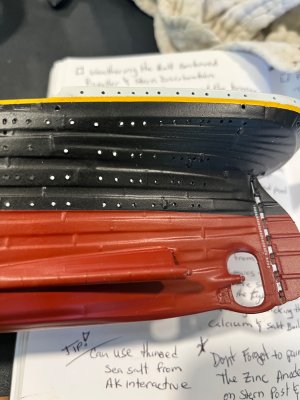
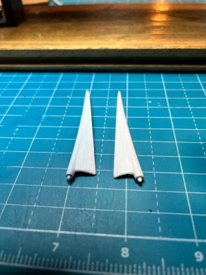
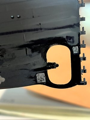
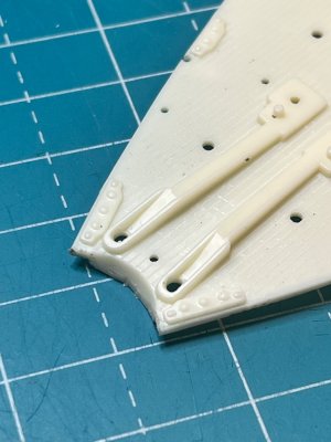
One of the first things about the propeller wings is that they have A LOT of extra material, especially at the forward part of the pieces. Therefore, I modified them to look more industrial and fit much better. After carfully sanding and some Mr Dissolved Putty applications, I got them about where I wanted.

Propellers Wings 3.jpg

Dry fitting them top the hull required some extra sanding to the hull mounting site and some further part sanding to make them look realistic without losing the molded details.

Propellers Wings 2.jpg

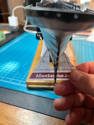
Then came the arch of the wings and what degree were they mounted on the actual ship. From files by Harland and Wolff and the website https://www.titanicology.com/Titanica/SpeedandRevolutions, I determined that the "canted angle" or spread was 2 degrees pitch past centerline, or more precisely 22.5 degree angle from the centerline. I made a template that I cound tape to the stern and get the angles correct (you can see me shakely hold my template to the wings after installation).

Propellers Wings 4.jpg

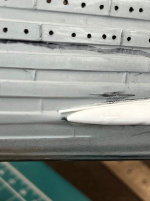
Then begun the chore of making the propeller wings seem like that at mounted to the hull in a realistic fashion. I did use 5 minute epoxy to adhere the wings (learned my lesson). I used 0.25 mm rod to fill in gaps and careful applications of putty and some judicial sanding eneded up with a product I liked (after installing the exterior hull parts and additions I primed the hull with black Mr 500 Primer and carefully sanded away any hull irregularities, blemishes, scratches and then primed Mr 1000 Primer and so on). I did not install the actual propellers because I know at some point I will knock them off. The propellers I plan to use is from China 3D and I will use the three (3) prop central propeller. I know the controversy but the article by Bob Read is too compelling! He found photographic evidence known to be the Titanic that indicates a three prop propeller sitting on dock ready for installation. I would suggest reading those articles on Titanic Cad Plans website home page.

Propellers Wings 5.jpgTransom Propellers 1.jpg

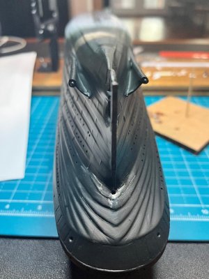
The Rudder was next and I went right to the China 3D part. This was pretty straight forward with clipping off the gimbels and pintel mounts on the stern post. There is nearly no modifications that were needed other than enlarging the hole for the rudder post into the ship. I used E6000 adhesive because I would want this part to give a little if I accidentally grab the rudder instead of the hull when I am handling the model. You can also see I added the stern central propeller base plate and anodes.

Rudder 1.jpgStern Post Anodes Central Propeller.jpgTransom Propellers 2.jpgRudder 2.jpg

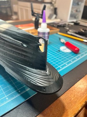
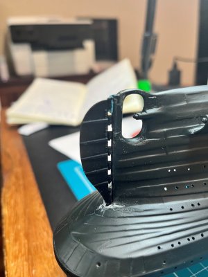
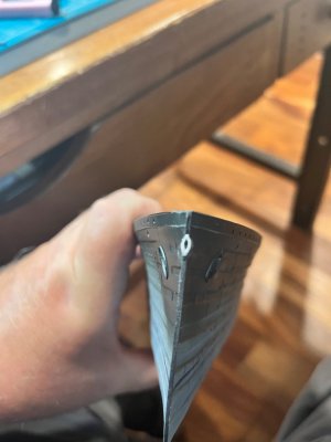
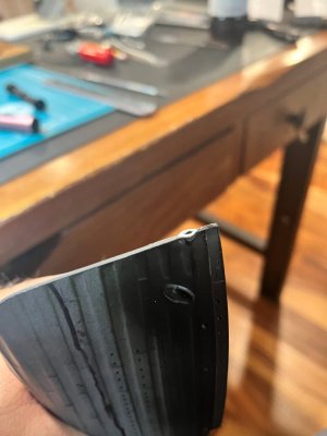
Next was the Bow Central Anchor Hawsehole. Though I did get the insert part from China 3D, I was not confident to make that serious of a major modification. I have spent some money on this model and did not want to ruin it with a hack job. Time for some magic. I know that a piece of circular plywood was attached to the hawsehold when the Titanic was at sea (which I am depicting at sea on April 13th, 1912) which I have heard is what Minicraft was trying to achieve. But I wanted the dramatic effect of seeing the bow and that awesome hawsehole. I took a piece of 0.25 mm thick styrene plastic and shaped it to the correct proportions using the China 3D piece as the guide. I drilled the central hole at ~30 degree up to the anchor well, and used a round file and dremel tool to grind the opening to the shapes I wanted and voila!

Central Anchor Hawsehole 1.jpgCentral Anchor Hawsehole 2.jpg

I then sanded the piece nearly smooth (it s just a little proud of the prow, but with the flat black paint, I doubt if you can see it) and fiddled with the sides until I was statisified with the results.

Next up was the condenser ports on the aft section of the exterior hull in line with funnel number 4 on both sides.

Condenser 3.jpgCondenser 4.jpg

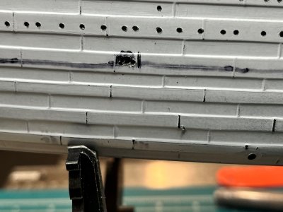
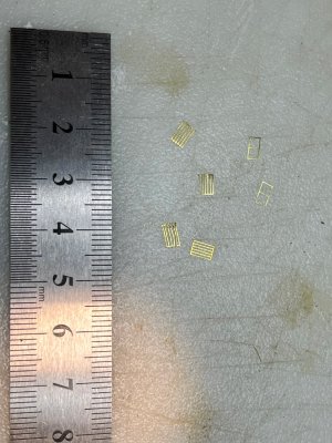
I followed Rivet Counter and the Titanic Cad Plans on the locations of the condenser outputs at the water line and and the inlets at the bilge keel level of the hull. I did find that TheModelBoatGuy on YouTube measured out the dimensions of the grills for 1:350 scale, so I used those measurements for my model (thank you to all those who diligently make videos of their fantastic builds and tips for modeling). I didn’t have the PE parts you can obtain in 1:200 scale but I wanted that same effect, so I scratch built the interior space for some depth after drilling out the rectangle shape and then used the extra parts I had from GMM PE rails for the cranes and made grills from railing panels. I will install the inlets after weathering the hull to prevent knocking parts off at such an obvious rub point.


Condenser 2.jpgCondenser 1.jpgT

Wooweee! That was a lot and obviously I did not do all that work in one sitting. I started at the beginning of April 2026 and now have reach the point of painting.

But before that I will have a post on my adventures in model illumination. I am actually pleased with my results but I had to really engineer what and how I was going to light this candle.

Happy Modeling - Pete

Propellers Wings 1.jpg

Propellers Wings 6.jpg
 
Last edited:
Good Day Modelers,

The propeller wings as promised

View attachment 612647View attachment 612648

One of the first things about the propeller wings is that they have A LOT of extra material, especially at the forward part of the pieces. Therefore, I modified them to look more industrial and fit much better. After carfully sanding and some Mr Dissolved Putty applications, I got them about where I wanted.

View attachment 612635

Dry fitting them top the hull required some extra sanding to the hull mounting site and some further part sanding to make them look realistic without losing the molded details.

View attachment 612634

Then came the arch of the wings and what degree were they mounted on the actual ship. From files by Harland and Wolff and the website https://www.titanicology.com/Titanica/SpeedandRevolutions, I determined that the "canted angle" or spread was 2 degrees pitch past centerline, or more precisely 22.5 degree angle from the centerline. I made a template that I cound tape to the stern and get the angles correct (you can see me shakely hold my template to the wings after installation).

View attachment 612636

Then begun the chore of making the propeller wings seem like that at mounted to the hull in a realistic fashion. I did use 5 minute epoxy to adhere the wings (learned my lesson). I used 0.25 mm rod to fill in gaps and careful applications of putty and some judicial sanding eneded up with a product I liked (after installing the exterior hull parts and additions I primed the hull with black Mr 500 Primer and carefully sanded away any hull irregularities, blemishes, scratches and then primed Mr 1000 Primer and so on). I did not install the actual propellers because I know at some point I will knock them off. The propellers I plan to use is from China 3D and I will use the three (3) prop central propeller. I know the controversy but the article by Bob Read is too compelling! He found photographic evidence known to be the Titanic that indicates a three prop propeller sitting on dock ready for installation. I would suggest reading those articles on Titanic Cad Plans website home page.

View attachment 612637View attachment 612639

The Rudder was next and I went right to the China 3D part. This was pretty straight forward with clipping off the gimbels and pintel mounts on the stern post. There is nearly no modifications that were needed other than enlarging the hole for the rudder post into the ship. I used E6000 adhesive because I would want this part to give a little if I accidentally grab the rudder instead of the hull when I am handling the model. You can also see I added the stern central propeller base plate and anodes.

View attachment 612649View attachment 612651View attachment 612640View attachment 612650

Next was the Bow Central Anchor Hawsehole. Though I did get the insert part from China 3D, I was not confident to make that serious of a major modification. I have spent some money on this model and did not want to ruin it with a hack job. Time for some magic. I know that a piece of circular plywood was attached to the hawsehold when the Titanic was at sea (which I am depicting at sea on April 13th, 1912) which I have heard is what Minicraft was trying to achieve. But I wanted the dramatic effect of seeing the bow and that awesome hawsehole. I took a piece of 0.25 mm thick styrene plastic and shaped it to the correct proportions using the China 3D piece as the guide. I drilled the central hole at ~30 degree up to the anchor well, and used a round file and dremel tool to grind the opening to the shapes I wanted and voila!

View attachment 612641View attachment 612642

I then sanded the piece nearly smooth (it s just a little proud of the prow, but with the flat black paint, I doubt if you can see it) and fiddled with the sides until I was statisified with the results.

Next up was the condenser ports on the aft section of the exterior hull in line with funnel number 4 on both sides.

View attachment 612645View attachment 612646

I followed Rivet Counter and the Titanic Cad Plans on the locations of the condenser outputs at the water line and and the inlets at the bilge keel level of the hull. I did find that TheModelBoatGuy on YouTube measured out the dimensions of the grills for 1:350 scale, so I used those measurements for my model (thank you to all those who diligently make videos of their fantastic builds and tips for modeling). I didn’t have the PE parts you can obtain in 1:200 scale but I wanted that same effect, so I scratch built the interior space for some depth after drilling out the rectangle shape and then used the extra parts I had from GMM PE rails for the cranes and made grills from railing panels. I will install the inlets after weathering the hull to prevent knocking parts off at such an obvious rub point.


View attachment 612644View attachment 612643T

Wooweee! That was a lot and obviously I did not do all that work in one sitting. I started at the beginning of April 2026 and now have reach the point of painting.

But before that I will have a post on my adventures in model illumination. I am actually pleased with my results but I had to really engineer what and how I was going to light this candle.

Happy Modeling - Pete

View attachment 612633

View attachment 612638
Nicely done Pete! Regards, Magic Mike
 
Now let’s talk about illumination

It was the first full decision I made after my deciding on the Minicraft kit. Now illuminating a model has a host of considerations that you need to plan for from the beginning of you build. Fiber optics vs. LED, Remote vs. Switch activation, plug-in vs. battery or USB powered, and so on. Finding the right lighting effect that is period representative is not as hard as it was several years ago. The trend for the younger generations to illuminate their rooms with soft light has brought many new products that can easily match my requirements. Then the consideration of how to display your finished product. Open display vs. encased display. Which day or night on Titanic's voyage (I am depicting April 13th, 1912 out to sea).

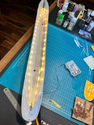
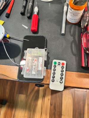
So I have mentioned this before in previous posts, but for those strictly interetsed in just how I illuminated my kit, I decided to present an encased table top display that can be moved. That means remote controlled and battery operated, incandesent light, long lasting lasting battery life so that I would not have to un-case the display to change the batteries often. I also decided on LED lighting and not fiber optics because the amount of work for my return of investment was better using just LED lighting. These decisions now caused other considerations such as how to mount the ship in such a way that the batteries can be accessible without being seen and not distrubing the model if I did have to change the batteries. The traditional pedestal mount would not work. Therefore, I decided on the "dry dock" display method with a hiddened chamber under the ship for the remote signal and battery pack.

The other challenge was the materials that the kit was made from Minicraft. The black hull is terrific, but the white and buff plastic walls and decks are notorious for having light glow throught the materials. That means I need to plan on stopping light leaks from the decks and walls, and the joints where the kit parts are installed on the model. So the plan is to used flat black on the underside of the decks as a light blocker followed by white gloss paint for reflection purposes (I tried Mr Surfacer 1000 but found that there was still a little bit of glow through the decks). I will prime all the wall/ bulkhead pieces and may have to improvise on the contact points with a 0.25 mm by 0.25 mm styrene plastc strip as a border around the bases of the deck structures to prevent light leaking where I dont want it :p

Now the plan

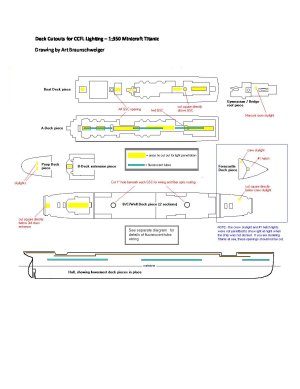
I loved what Art Braunschweiger did with illumination. In fact, I mostly used his diagram from his website titanicmodel.net. However, his source of lighting was completely different from mine, so I had to modify that plan to my needs. Also, I will not light up forecastle crew galley skylight or hatch #1 because I am depicting the ship out to sea (3rd day) and at night those areas were not illuminated for nighttime navigation and visibility (no lookout binoculars though?).
I will be illuminating the poop deck and forecastle C-Deck windows and portholes that are visible from the well decks.

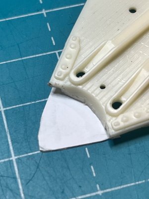
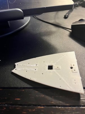
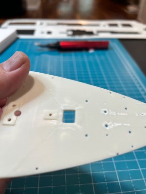
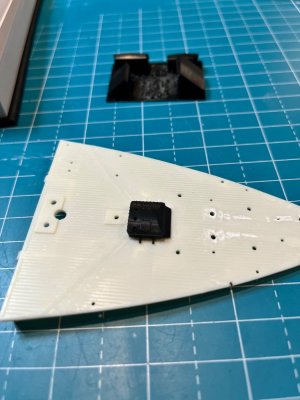
deck_cutouts_for_ccfl_lighting.jpg

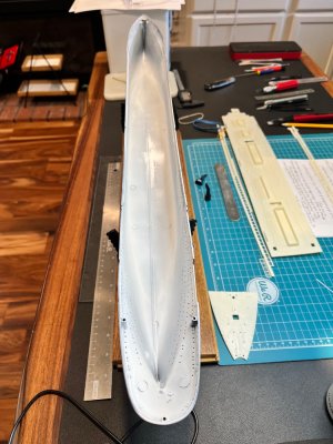
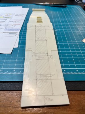
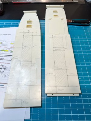
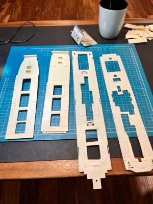
So I already discussed how I painted the interior of the hull first with gloss white. But now I need to modify the decks for maximum illumination. I planned out the areas I wanted to cut, including cross sections that where not cut as braces for the decks for strength.

IMG_0003.jpegIMG_0004.jpegIMG_0006.jpeg

I then cut the crossed out sections using my good ole dremel with a saw blade

IMG_0005.jpegIMG_3098.jpeg

I was satisfied with the cuts and cleaned off the burrs from the cuts. Then I painted the underside of the decks first with flat black and then a gloss white for reflection. Then I carefully painted the topside of certain decks (A and B Decks) in the locations that would not be visible after installing the bulkheads and walls so the light could be reflected up to the decks above. I am planning on using Scale Deck or a similar wood verneer so I need to be careful on painting the upper portions of the deck where it might be visible through the material.

Now A Deck has these protrusions which I did remove before cutting out the deck. I again left some parts for strength at strategic locations as you can see above. The final cuts for B-Deck, A-Deck and the Boat-deck came out pretty well and I was able to correct some deck warpage too (Bonus!).

IMG_0007.jpeg

I had searched earlier for incandescent period lights with those requirements for remote control and wireless. The one I liked the best was Echosari Battery Powered Led Strip Lights with Remote Warm White, 8 Modes, Dimmable, Timer, Self-Adhesive, Cuttable, Waterproof, 9.8FT 90 Led Strip Lights. This was enough LED strip to cut into managable lengths and have the ability to soder more strips if I need more illunination above decks.

IMG_0008.jpegIMG_0009.jpegIMG_0011.jpeg

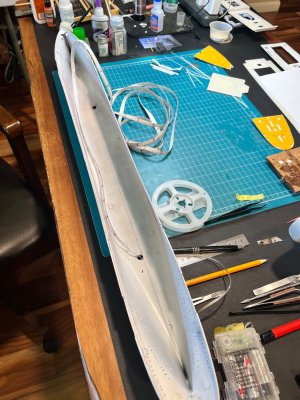
FYI, I completed painting the full hull and sealing it with Testor's Glosscote prior to final LED Installation. That way I am not messing around with cordage and battery packs while masking and painting the hull (hard enough with the sheer line without adding the lighting items).

IMG_0010.jpeg

I did add HVAC aluminum chrome tape on the bottom of the hull to assist in the reflection factor. You can almost see that the lights through my drilled out portholes (I will updated a photograph with a dark room to shown the light more fully). Success!
IMG_3283.jpeg
Masking and painting the hull posts is up next since you can see my nearly finished hull (need some very slight weathering, decals, Dullcote, and filling porthole with Testor's window cement) in the above picture.

Happy Modeling - Pete
 
Last edited:
Moving on to painting

However, before I put pigment onto plastic, I wanted to finish details on the upper superstructure so when I do paint the flat white I could paint it all the same time (the hull superstructure and the A-Deck upper superstructure). This will add details and interesting depth to it promenade (I am also adding the ceiling girders to the visible portions of A-Deck and the. Boat Deck).

IMG_3060.jpegIMG_3063.jpegIMG_3065.jpeg

As you can see there is a lot of windows on the 1st Class Promenade that can be seen and see through. So I plan to take 0.5 mm strip styrene and install the interior supports to the windows on to the upper superstructure.

IMG_3072.jpeg

Then I added the strips to the windows frames from the bow to the stern on the kit parts. The plan will be to cut individual acetate window squares for each one

IMG_3074.jpegIMG_3073.jpeg

Next up was to add the knuckle line along the bottom part of the windows from the forward section of the promenade rail cap to the aft promenade rail cap which is about 25 cm in length. I used 4 lb monofilament fishing line (which is had issues with) as the material for the line. I did not cut the line into more manageable lengths because I wanted a straight, unbroken line from fore to aft. Therefore, I had to use clamps and CA adhesive to install the line (the line wanted to curve and not take the CA without clamping the line). I used the same method to add the same type of line above the promenade windows.

IMG_3067.jpegIMG_3068.jpegIMG_3070.jpeg

You can see where I installed the Coal Bunker Outriggers after I added the knuckle lines. I used Titanic Cad Plans, Ken Marshall’s work, and The Ship Magnificent for positions and locations of the outriggers. There actually two sets of of outriggers on each side of the Titanic (fore and aft).

Now to masking the hull.

I have to apologize first because I have lost the photos of of me actually painting the hull and more of the way I masked the the hull. I started with Tamiya XF-1 Flat Black. I could have used NATO Black but want that color to highlight the hull stake plating to add depth to the black portion of the hull (I painted the entire hull). I let the paint cure for 24 hours.

IMG_3064.jpeg

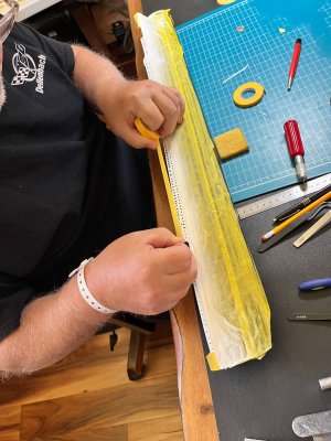
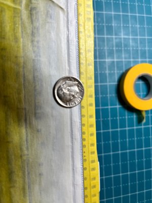
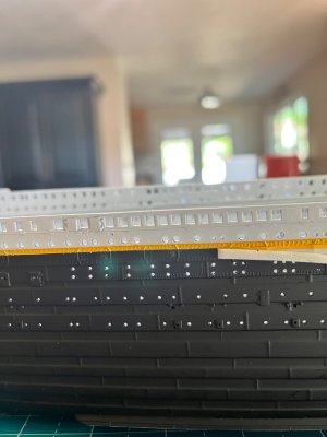
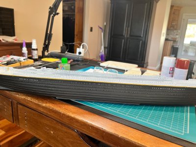
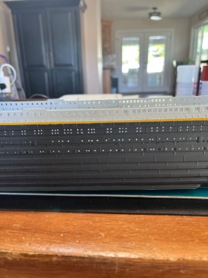
I then masked the black part of the hull up to the bottom line of the natural Sheer line (just below the row of double rivets detail). I first used 3 mm masking tape to mark the bottom line. I used a square eraser to snug down the edges and ensure to minimize the paint bleed. Then I used 10 mm and 45 mm tape to finish masking the bottom of the hull. The stern was masked with 3 mm tape carefully below the portholes at the knuckle line.

IMG_3078.jpegIMG_3079.jpeg
Then I painted the white hull superstructure using Tamiya XF-2 Flat White. When we get to the Sheer Line, the yellow chromate paint shows better on white paint vs. the flat black. So that means I painted from the bottom of the sheer line all the way up. I allowed the Flat White to cure for 48 hours. I plan to use off white and soft tone washes to add depth and tone to the stark flat white paint on other details and parts of the superstructure.

The Sheer Line

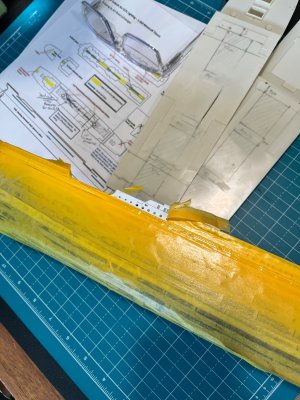
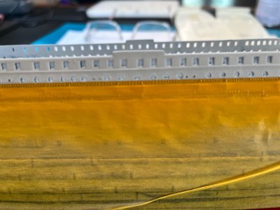
Now it’s time to tackle the sheer line that I heard so much about. Some modelers have painted the line yellow first, then mask the line with a 1 mm tape. But I thought that was more difficult because of those notorious rivets and paint bleed. I choose to mask off the white paint area at the top of the sheer line and above (so the black hull and the white superstructure where the areas that were masked). I again used the 3 mm tape and the eraser method to prevent bleeding. And added increasing sizes for the rest. This leaves the dreaded row of rivets exposed and not causing interfering protrusions the allow the paint to seep in and marr your paint job. Moreover, at the stern there is serious curve at the aft rub line just under the vertical transom plates. I did not want to try to curve the normal Tamiya masking tape. It wrinkles and allows gaps to occur for paint bleed. Therefore, I used Tamiya 3 mm curve tape (more like a plastic flex tape) to make the curve as flat as possible. I had to really apply more pressure to secure the flex tape with a dental tool I have from other projects. Then I further secured that flex tape with regular masking tape to block off the rest of the hull.

IMG_3082.jpegIMG_3081.jpeg

I had to used several coats of the yellow chromate to get the correct tone and hue of the sheer line. I allowed the yellow to cure for an additional 48 hours before removing the masking tape.

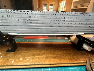
I carefully removed the tape at every level. I found crisp clean lines except at a couple of minor points that was easily touched up (it was actually the flat white that bleed onto the black). I was very careful because I have seen a couple of videos on YouTube were the yellow would peel off worse the masking tape.

IMG_3091.jpegIMG_3092.jpegIMG_3093.jpegIMG_3094.jpegIMG_3096.jpegIMG_3095.jpeg
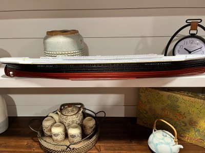
I then masked the waterline for the anti-fouling paint. I used XF-33 Tamiya Hull Red for the lower portion. I know then there is some really compelling evidence. That the anti-fouling paint was closer to a pink color. However, I wanted to use the lighter shades of red for highlights of the rows of hull plating.

I did follow the molded waterline that Minicraft provided verified by resources and photographs. I wanted to make sure that I had the correct waterline at the rudder (which was just above the second top stake). I needed to be precise at the bow where the waterline reaches the prow. The decals I plan to use actually has a precise positioning requirements to properly fit on the model. After several coats of paint, I removed the last of the masking tape and seal the entire hull and upper superstructure with Testor’s Glosscote (for adding decals and weathering). Dullcote flat varnish is more “rough” in texture and provides air pockets that causes silvering on the decal and crevices where weathering washes seep in and is not easy to blend as the smoother Glosscote varnishes.

IMG_3102.jpeg

To can see the final product on the shelves next to my workbench. I am happy with the results.

The Forecastle and Poop Deck parts modifications are next

Happy Modeling - Pete


IMG_3060.jpeg

IMG_3063.jpeg

IMG_3064.jpeg

IMG_3065.jpeg

IMG_3066.jpeg

IMG_3067.jpeg

IMG_3068.jpeg

IMG_3069.jpeg

IMG_3070.jpeg

IMG_3072.jpeg

IMG_3073.jpeg

IMG_3074.jpeg

IMG_3095.jpeg

IMG_3094.jpeg

IMG_3093.jpeg

IMG_3092.jpeg

IMG_3091.jpeg

IMG_3096.jpeg

IMG_3102.jpeg

IMG_3082.jpeg

IMG_3079.jpeg

IMG_3081.jpeg

IMG_3078.jpegIMG_3081.jpeg
 
Last edited:
Moving on to the forecastle and poop decks.

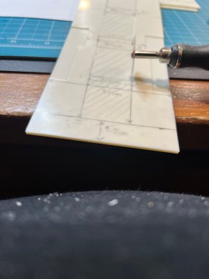
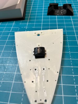
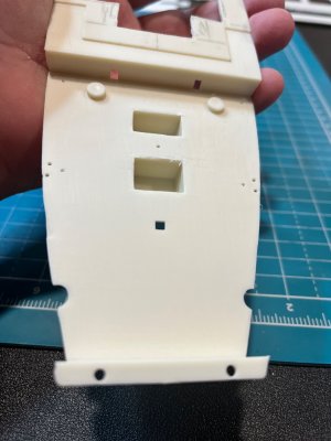
I am not strictly following the kit instructions by this point, and have moved on to modular construction and installation techniques. I decided to finish the forecastle and the poop deck to the point I can spray the dadoe line (the reddish orange paint (dark mast for me) in the fore and aft well decks bulkheads, bulwarks, and crane bases).

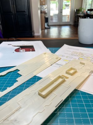
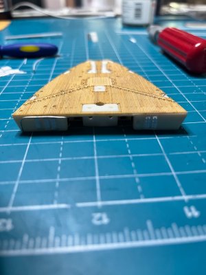
First I decided to improve the central anchor well on the forecastle. I cut off the existing well deck because it looked clunky and out of scale. I decided to reshape the well and make it look more industrial. I also have the China 3D central anchor and Toms PE gratings for the well and wanted a more three dimensional look. Following that train of thought, I decided to remove all the forecastle deck details that will be replaced by China 3D accessories, I also remove the planking mold lines to create a flat surface for installing the wooden deck veneer.

IMG_2923.jpegIMG_2925.jpegIMG_3056.jpeg

IMG_3115.jpegIMG_3056.jpeg

So with the 3D parts I ended up removing nearly all of the details except the winch pad and steam conduits platform. This resulted in the breakwater piece molded on the deck to look out of scale and bulky. So I will removed that portion and will scratch build that piece prior to installing the foreastle to the hull. You can see the #1 hatch from China 3D was less substantial in its mass than the orignial molded kit hatch.

IMG_3108.jpegIMG_3109.jpeg

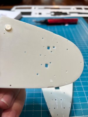
Now I can work on the underside of the forecastle. I added the bulkhead kit parts. But the watertight hatches that were provided for the front were protruding far out from the wall. So I sanded the backs down to a more reasonable scale. I also had to add 5 additional doors and hatches in the interior portion of the forecastle. Using Rivet Counter and Titanic CAD Plans, I add four doors inside and a fifth door just left of the portside watertight doors (there no additional door on the starboard side aft facing bulkhead). I also installed the water / drain line on the Portside that curves first up and starboard, then foreward under the decking with 20g wire.

IMG_3121.jpegIMG_3122.jpeg

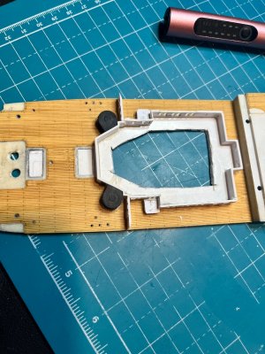
Now I can install the wooden deck and mask the areas for future painting. I wanted to install the decking so that I can add a trim piece 0.5 mm strip to the aft upper edge of the forecastle level with the deck as a border. I wanted to paint this addition at the same time I painted to the rest of the structure.

IMG_3124.jpegIMG_3125.jpeg
I also worked on the stern bulkhead to the central anchor well to flush it out and make it more angular than it was molded in.

IMG_3119.jpegIMG_3120.jpeg

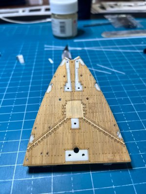
Installing the Artwox deck means that I have to deal with the adhesive backing on the veneer. Now I havent had as much trouble with these type of decks (I believe Pontos and KA uses the adhesive too), I tend to remove the backing carefully, and then apply a thin coat of Gorilla Wood Glue as per the instructions onto the veneer adhesive and allow it to dry for about 5 minutes. This tends to remove some of the stickiness and you can maneuver the piece more. I also applied a thin amount of glue to the plastic deck. When these two piece make contact, they re-activate the wood glue and makes a solid point of adhesion for the pieces. Installing the deck is straight forward by working from the middle, then outward applying pressure to make great contact with the parts. I did not have to use clamps at get a good seal and I am happy with the results. In addition, I installed the wood decks on the poop deck and the well decks parts. In hindsight, i should have waited on the well decks until I was ready to install the other deck details soon after (Saves wear on the decks). As a side note, you need to apply a varnish of your choice to the un-installed veneer decks. This prevents dirt, greesy fingers, and some scratches from soaking in on your decks.

IMG_3113.jpegIMG_3126.jpegIMG_3127.jpeg

The poop deck has actually more modifications with the walls under the poop deck and the bar 3rd class bar needing adding to the structure. There were only a few walls that are somewhat out of scale. I also added the windows and doors found under the poop deck to the 3rd class common areas. I also plan to add edging in the same manner as the forecastle at the forward portion of the upper poop deck.
There is other details I need to add to the underside of the poop deck like the stanchions, the crane supports that are found directly under the poop deck cranes, and of course the ladder under the set of stairs to the well deck. Some ask about those ladders (they can be found under the stairs for the forecastle too) I refer them to an article by Bob Kerns in Titanic CAD Plans that shows a photo where the stairs were removed off to the side so that the cargo hatches can be filled in the well decks. It clearly shows the crew working the cranes with the stairs out of the way and persons climbing the ladders to the poop deck.

IMG_3128.jpegIMG_3116.jpegIMG_3117.jpeg


I will upload more pictures in future posts on the well decks, B-Deck prep, and painting the cranes, bulkheads, and bulwarks with the dadoe line.

Happy Modeling - Pete

IMG_2923.jpeg

IMG_2925.jpeg

IMG_3056.jpeg

IMG_3108.jpeg

IMG_3109.jpeg

IMG_3114.jpeg

IMG_3115.jpeg

IMG_3113.jpeg

IMG_3116.jpeg

IMG_3117.jpeg

IMG_3119.jpeg

IMG_3120.jpeg

IMG_3121.jpeg

IMG_3122.jpeg

IMG_3123.jpeg

IMG_3124.jpeg

IMG_3125.jpeg

IMG_3126.jpeg

IMG_3127.jpeg

IMG_3128.jpeg
 
Last edited:
Amazing progress PeteG! I know I have been silent on this post for a while, but coming back to this thread, so much has been done! It seems every time I take a look at this thread, an entirely new part of the ship has been finished. I can never really put this into words, but this is quite the undertaking. (The best I can do is take pre-molded and pre-colored parts and snap them together (LEGO)). Thank you for sharing this journey with this community, and I hope everything is SHIP SHAPE! (:
 
Amazing progress PeteG! I know I have been silent on this post for a while, but coming back to this thread, so much has been done! It seems every time I take a look at this thread, an entirely new part of the ship has been finished. I can never really put this into words, but this is quite the undertaking. (The best I can do is take pre-molded and pre-colored parts and snap them together (LEGO)). Thank you for sharing this journey with this community, and I hope everything is SHIP SHAPE! (:
Thank You so much. I am finally catching up to where I am currently in the build.
 
I had some bad experience before with the wooden decks on plastic models, and I almost forbid myself to buy them :D But your Artwox Titanic deck in 1:350 makes me reconsider! Thumbsup
 
I had some bad experience before with the wooden decks on plastic models, and I almost forbid myself to buy them :D But your Artwox Titanic deck in 1:350 makes me reconsider! Thumbsup
You know I was a little worried too, but followed YouTube videos by guys like Ben at The Midwest Model Shop and TheModelBoatGuy and it worked
 
Lets talk about the Dadoe Line

Per Wiki, This is a area painted for high traffic areas such as the well decks. Third class passengers used these areas for recreation. Also your main cargo hatches are mostly located on the well decks along with the 3t cranes. So, the paint scheme was designed to hide the dirt, scuffs, and soot that would have surely occurred on an operational cruise ship of that time period.

As we know the top section is painted flat white and the lower section is painted Dark Mast. Now what is the color dark mast??? Its described as a reddish/ rust / brownish/ orche color. I decided to follow Bob Read's articles Color Guide for Olympic Class Ships and An Examination of the Color “Dark Mast” Found on Titanic at Titanic Cad Plans.

1782842683646.png

I found that Scale Colors from Squadron matches what Bob Read presents as above. Now this is acrylic vs enamel paint. However, I have found no issues painting acrylic over enamels that are well cured (Finescale Modler Forum June 8, 2009). I have decided to give arcylic a chance since I believe that in the future enamels will be phased out.

I proceeded to dry fit all the structures (A later post on creating the B-deck structures). As discussed before, I decided on China 3D printed cranes and the fore well aft bulkheads. I needed to set the dadoe line on those pieces, the bulkheads, and the bulwarks. According to AI the dadoe line is said to be at waist level? what is that in 1/350 scale? Therefore, I measured the bulwarks height as they were installed on the hull and found them to be 3.5 mm in height (slightly above waist level in 1/350 scale if normal height at that time was 5'8" tall (4.93 mm)). However, all pictures and articles agree that the bulwarks were painted a solid dark mast color up to its rail cap edge (flat white). Those pieces measured at 3.5 mm height. So that was the height of the top of my dadoe line :)

IMG_3166.jpegIMG_3167.jpegIMG_3168.jpeg

Now I had a bunch of pictures showing me grumble through the masking part, but somehow through the process, I deleted them :(

I painted all the structures with primer (light leaks prevention) and then Tamiya flat white and allowed that to dry for 24 hours.

Suffice to say masking the forecastle and poop deck underneath bulkheads was a journey in patience. I had to do some modifications and additions to get a straight dadoe line in those areas and not make a complete mess out of it. Also, all those structures, the second class library with the aft bulkhead, the fore well deck aft bulkhead, and the crane bases all needed to be built and matched to look correct. There was a lot of dry fitting and measuring to get everything correct. I used my IPhone camera and took a lot of pictures to check if the line was level and straight on all objects from ground level. The use of 1 mm tape was a lifesaver! It allowed me to manipulate the tape around corners, over doors, around bases, and so on....

You can see the color came through really well on the pieces and I allowed them to cure for 24 hours. Unmasking went without a hitch. Touch up was minimal, only at the forecastle doors did a get some slight bleed. I then applied Testors Glosscote on all painted surfaces for future light weathering.

IMG_3201.jpegIMG_3202.jpegIMG_3204.jpeg

IMG_3203.jpeg

Now a tricky part was the B/C Deck aft fore well bulkhead. you can barely makeout in that last pic the corner stay line braces that protruded out from the wall on the corners to the hull well deck bulwarks (wow that was a mouth full). The underside is dark mast and the top is flat white. It was easier to just mask it up and then apply the dadoe color to the underside and allow that to cure at a different time.

Now my question is should I grind out the interior edges on the plastic hull well deck and then install the bulwarks?

The hull thickness on the model is already out of scale (1.5 mm actual), and installing the China 3D pieces is going to make it even further out. This is one of the parts I should have plan and decided upon prior to painting my hull. The China 3D part is only 0.5 mm thick, but that makes the entire thickness at ~ 2 mm. The Titanic's actual bulwark plating was 3/4 to 1 inch thick (0.08 mm at 1/350 scale). Well that isnt going to work because the actual coats of paint will be thicker than the plastic at that rate. So is it movie magic time and I can just mask the exterior, and carefully, at slow speed grind/sand the extra material without harming the exterior paint job (total thickness with bulwark at 1 mm thickness). Or do I attach them as is and move on???

Decisions decisions...

Happy Modeling - Pete
 
Last edited:
Lets talk about the Dadoe Line

Per Wiki, This is a area painted for high traffic areas such as the well decks. Third class passengers used these areas for recreation. Also your main cargo hatches are mostly located on the well decks along with the 3t cranes. So, the paint scheme was designed to hide the dirt, scuffs, and soot that would have surely occurred on an operational cruise ship of that time period.

As we know the top section is painted flat white and the lower section is painted Dark Mast. Now what is the color dark mast??? Its described as a reddish/ rust / brownish/ orche color. I decided to follow Bob Read's articles Color Guide for Olympic Class Ships and An Examination of the Color “Dark Mast” Found on Titanic at Titanic Cad Plans.

View attachment 615902

I found that Scale Colors from Squadron matches what Bob Read presents as above. Now this is acrylic vs enamel paint. However, I have found no issues painting acrylic over enamels that are well cured (Finescale Modler Forum June 8, 2009). I have decided to give arcylic a chance since I believe that in the future enamels will be phased out.

I proceeded to dry fit all the structures (A later post on creating the B-deck structures). As discussed before, I decided on China 3D printed cranes and the fore well aft bulkheads. I needed to set the dadoe line on those pieces, the bulkheads, and the bulwarks. According to AI the dadoe line is said to be at waist level? what is that in 1/350 scale? Therefore, I measured the bulwarks height as they were installed on the hull and found them to be 3.5 mm in height (slightly above waist level in 1/350 scale if normal height at that time was 5'8" tall (4.93 mm)). However, all pictures and articles agree that the bulwarks were painted a solid dark mast color up to its rail cap edge (flat white). Those pieces measured at 3.5 mm height. So that was the height of the top of my dadoe line :)

View attachment 615895View attachment 615896View attachment 615897

Now I had a bunch of pictures showing me grumble through the masking part, but somehow through the process, I deleted them :(

I painted all the structures with primer (light leaks prevention) and then Tamiya flat white and allowed that to dry for 24 hours.

Suffice to say masking the forecastle and poop deck underneath bulkheads was a journey in patience. I had to do some modifications and additions to get a straight dadoe line in those areas and not make a complete mess out of it. Also, all those structures, the second class library with the aft bulkhead, the fore well deck aft bulkhead, and the crane bases all needed to be built and matched to look correct. There was a lot of dry fitting and measuring to get everything correct. I used my IPhone camera and took a lot of pictures to check if the line was level and straight on all objects from ground level. The use of 1 mm tape was a lifesaver! It allowed me to manipulate the tape around corners, over doors, around bases, and so on....

You can see the color came through really well on the pieces and I allowed them to cure for 24 hours. Unmasking went without a hitch. Touch up was minimal, only at the forecastle doors did a get some slight bleed. I then applied Testors Glosscote on all painted surfaces for future light weathering.

View attachment 615898View attachment 615899View attachment 615901

View attachment 615900

Now a tricky part was the B/C Deck aft fore well bulkhead. you can barely makeout in that last pic the corner stay line braces that protruded out from the wall on the corners to the hull well deck bulwarks (wow that was a mouth full). The underside is dark mast and the top is flat white. It was easier to just mask it up and then apply the dadoe color to the underside and allow that to cure at a different time.

Now my question is should I grind out the interior edges on the plastic hull well deck and then install the bulwarks?

The hull thickness on the model is already out of scale (1.5 mm actual), and installing the China 3D pieces is going to make it even further out. This is one of the parts I should have plan and decided upon prior to painting my hull. The China 3D part is only 0.5 mm thick, but that makes the entire thickness at ~ 2 mm. The Titanic's actual bulwark plating was 3/4 to 1 inch thick (0.08 mm at 1/350 scale). Well that isnt going to work because the actual coats of paint will be thicker than the plastic at that rate. So is it movie magic time and I can just mask the exterior, and carefully, at slow speed grind/sand the extra material without harming the exterior paint job (total thickness with bulwark at 1 mm thickness). Or do I attach them as is and move on???

Decisions decisions...

Happy Modeling - Pete
Love the colors Pete!
 
Adding Decals and Weathering the Titanic Hull

So the date I am protraying is April 13th, 1912, Titanic's third day at sea. She has had her portside freshened with paint for the embarkation of the passengers at Southhampton, England prior to April 10th 1912, but now she has been to sea for three days. and has made stops at Cherbourg, France, and Queenstown Ireland.

According to the Weatherguys.com the date of April 10 - 13 was mostly clear skys, mild temperatures and moderate winds.

But sea water on a red and black hull will weather overnight (slightly). And remember that the starboard side was not freshened and had over 9 months exposure to rain and her sea trails. But Pete, Titanic is a new ship! you say. I agree, but inevitability the hull would shown some signs of weathering.

That is my goal is to shown enough that up close (2 -3 feet), you can see the signs of the sea salt's touch on the hull (slight on the port and a little more on the starboard). This is for modulation of the tones of the main colors and provide depth and interest. At longer distances (4+ feet), The color modulation will blend and the Titanic will look prestine as everyone imagines her to be. I dont want the plates to standout as hugh montrosities where the titanic at distance looked sleek.

But First!!! The decals.

The set of decals I used was Peddinghaus 1/350 scale for the Titanic. Several items that standout with these decals is that the name TITANIC is block and not italic or slanting like what is provided in the kit. The waterline marks were accurate for the bow (42') and have the right curve (plus there are other benefits from that set that include all the signage and so on). The aft waterline mark needs to be cut at 37' (the aft waterline mark goes to 42')

This is where you get to see if you made the waterline correct (fingers crossed). These decals were made for the Minicraft Titanic kit in 1/350 scale and are very precise. But I must have not had my pot of coffee yet when I masked out and painted my anti-fouling seaction and my lines at the bow and stern were correct. I had painted the hull before I got the decals so I was worrying a bit.
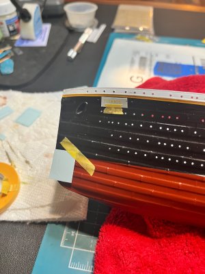
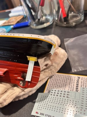
IMG_3258.jpegIMG_3259.jpeg

Now the Peddinghaus decal base is thicker than I anticipated, but when completed, the edges will smooth out with gloss and dull varnishes.
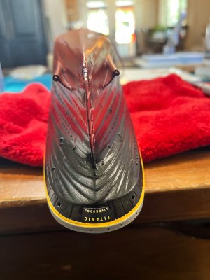
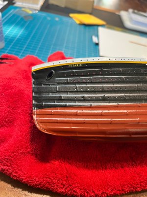
IMG_3261.jpegIMG_3262.jpegIMG_3263.jpeg

The photo of the stern exhibits how my modifications came out with creating the stern transom plates and the name plate (Upside down :P).

Now, Weathering!

White Superstructure
I used an off-white Scale Colors paint to highlight the doors, hatches, and other protrusions on the upper superstructure. This tone difference is enough to compliment the flat white at a distance, but moderates the brightness of the flat white up close, and provides varibility for interest. I added some very soft tone wash to highlight the molded and scraped doors, hatches, and other details (coal outriggers) on the superstructure. Then I took a damp cotton swab and removed most of the wash off after 5 mins. This made the jacklines at the bow standout some along with other details so that the outlines looked like shadows and created depth. I also used AK Interactive light rust on some parts such as the scuppers (very slight) and then addes just a few AK Interactive Sea Salt streaks to shown some very slight wear.
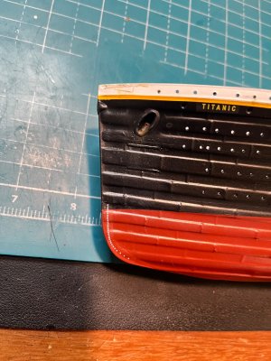
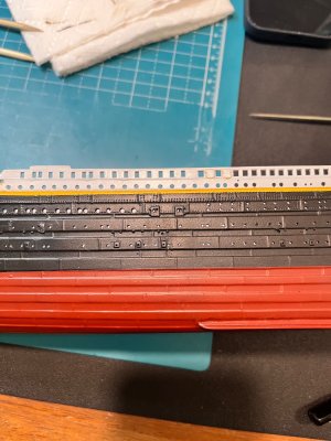
IMG_3289.jpegIMG_3293.jpeg

You can see in that bow pic that I started adding the rust at the port hawsehole. I used AK Interactive medium rust weathering paint. It matches what I believe fresh rust will appear (Bob Reads article explains that even with fresh paint, the rust would become visible within a couple of days with the anchor usage at port of calls). I also started adding the sea spray at the bow's wave creast that slightly flows toward the aft.

Black Hull
This is were my foundation of Flat Black comes in as blackground. I like washes and think I have become somewhat experienced, but I love the effect that drybrushing creates, especially with plates and ridges! It highlights the protrusions that I so carefully preserved during my hull modifications. My plan was to slightly use Tamiya brown wash combined with drybrushing with Tamiya Nato Black. This shoud create depth without becoming obvious. I only used a thinned down Nato Black drybrush on the hull plates very lightly to make them standout just a little. Then I switched to a more pigment verison of Nato Black to drybrush the hatches, doors, eyebolts, and rivets.
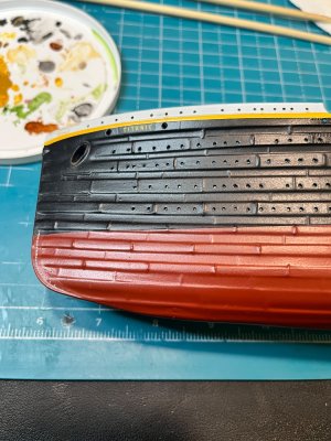
IMG_3301.jpegIMG_3303.jpegIMG_3308.jpeg

You can also see some very slight weathering on the starboardside at the protrustions flowing down toward the keel to mimic streaking. I added the same color mix to all the hawseholes, and every odd window or porthole. I then added very slight rust from the main anchor hawseholes and just a few sea salt weathering to the odd portholes as sea spray and rain streaks.
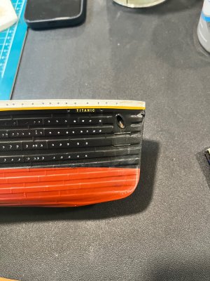
IMG_3298.jpegIMG_3285.jpegIMG_3293.jpegIMG_3308.jpeg

I added a very lighter version of the same weathering on the portside only at key points and, of course the rivets that I so painfully perserved.

Anti Fouling Red Hull
Well!!! let the controversay begin.

I say that because my buddy wanted me to paint the Anti-Fouling Red the pinkish color that Bob Read article very thoroughly explains. You can even get a version of this color from Vallejo Titanic Color Set.

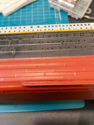
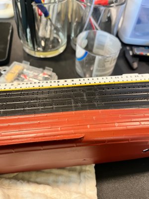
But, I like the darker Tamiya Hull Red as my base. This allows me to modulate the plate colors with a whiter/Pinker red (A drop of white or light grey) lightly drybrushed on protuding plates. You can barely see the affects on this bow pic where the inner plates are slightly darker than the risen plates. This toned down the Hull Red and created some depth. I tried to modulate weathering the plates to be somewhat different and interesting to look at when you stand closer. I did the same tone version around the entire lower hull because the freshened paint only reached down to the waterline, so the anti-fouling red would have been eveny weathered the same on bothside of the ship.

IMG_3289.jpegIMG_3285.jpeg

I did not use a brown wash for the lower plates to keep the whole hull effect a more lighter red. But I can change my mind in the future.

IMG_3303.jpeg

This last pic shows some very slight sea salt weathering with mostly thinner around the waterline. When the thinner evaporates, it leaves a slight mist mimicking the salt accumulation as the ship made its voyage. Again very little so that it creates some realism and interests with you view her up close.

Future weathering journeys.
I plan to continue with the slight weathering on the superstructure, A-deck, B-Deck, and Boatdeck structures. I will be switching to some ash and soot on the upper portions of the the decks that can be exposed to the funnels. Also some tonal washes and off-white to give the doors, windows, handrails, other equipment and devices to add variety and interest to the ship without over doing it. My goal is to be as accurate and realistic as I possibly can with this project.

Future Posts
B/C-Deck structures and the journey that awaited me.

Wish me luck and Happy Modeling - Pete G


IMG_3258.jpeg

IMG_3259.jpeg

IMG_3261.jpeg

IMG_3262.jpeg

IMG_3263.jpeg

IMG_3285.jpeg

IMG_3289.jpeg

IMG_3293.jpeg

IMG_3298.jpeg

IMG_3303.jpeg

IMG_3308.jpeg

IMG_3301.jpeg
 
Last edited:
Good Day Everybody !
I learned how to insert images so that they make more sense in this guide.

Moving on with the hull I started with the doors (mostly adding but some removal as per Rivet Counter guide) and windows and adding the missing portholes. I used Titanic-Cad-Plans, Ken Marshall paintings, Rivet Counter windows and doors, and the Ship Magnificent to try to get an accurate count of the doors, portholes and windows.

First was to add the missing portholes on the stern using the placement measurements as described in Rivet Counter. There are several other websites and youtube videos that discuss these portholes but I found that making a paper template/ stencil taped to the stern and a very sharp awl to create pilot holes for drilling was a better method for me. Then I drilled the stern hawse holes but made a mistake on the diameter and had to correct with tube styrene and re-drilled the holes to the correct size.

I also started etching stern transom plates. This required some time and patience to get the look just right and at the correct positions and spacing. Using the stern plating instructions from The Midwest Model Shop that was at 1:200 scale, I made another paper template with the correct dimensions by using a scale calculator website that converted the 1:200 scale to 1:350 scale. I liked the illusion of the details that the etching created for a more accurate representation of the stern.

Should be noted that I decided not to try and recreate the hull plating patterns in its entirety. I felt like going down that rabbit hole was not worth the ROI and time it would take. Making “representations” that creates an illusion to trick the minds eye to fill in the gaps was time and cost effective.

View attachment 612047View attachment 612048

I also added the stern Pad Eyes for the propellers and rudder I just received from China 3D prints, using the same instructions of the stern plating that included the pad eye positions on the hull (Verified by some period photographs of both the Titanic and the Olympic on the stern).

View attachment 612049


Moving on to the doors required adding B-deck private promenade door on the starboard side and the B-Deck 1st class entrance doors both sides of the hull. You can see I added the hinges to the doors where necessary. These door additions included the coaling doors or coal bunker doors on F-Deck (18 on port and 17 on starboard). I also added the 2 pad eyes just under the E-Deck hull plate stakes for each coal bunker door by just cutting bits from a 0.25 mm rod and installing them 2 each as a set above each door with a 2 mm spacing on each set.

I added etching in the well deck cargo hatches, making the wash ports/ scuppers on those doors, (open on the fore well and closed covers on the aft well cargo hatches). I had to cross reference the Titanic Cad Plans, the bulwarks on the well deck (their openings and hawse holes for the bollards), and other photographic evidence I could find on the correct placements of the cargo doors and scuppers. So many different parts interact with each other and it was really fun to figure out all the issues to incorporate accurate details to my hull and the well deck interior bulwarks. I can draw a bit and found that mapping out all the openings and details on the hull in my build logbook was immensely helpful. This allowed me to wrap my head around all the different factors and make a scaled template for my use.

I also added enhance etching to the B-Deck half hatches on both the forward and aft B-Deck promenades and the associated scuppers (fore rectangular and aft round)

View attachment 612045View attachment 612046

Also, the kit D-Deck 1st class entrance doors had a single "porthole" and not the side by side windows seen on all reference materials. I enlarged and squared the opening to the correct dimensions and added a crafted piece of photo etch brass to make the middle window frame.

Note: There was a lot of plastic residue and burrs from drilling out the portholes. I was using descending grades of sanding paper with sanding sticks and an electronic cordless hand sander to smooth out the portholes and windows (I found that the windows on the hull were out of shape and dimensions and I needed to file each one square) to preserve the molded hull details. In the interior of the hull I used an electronic drill to countersink each hole and remove its burrs to enhance their illumination factors.

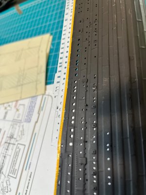
You can see where I also started on the bilge keel and the port and starboard propeller wings but more on those issues on another post

Happy modeling - Pete
Hi Pete!

Great work on all of the hull details. I think your decision to limit your time investment on the stern plating was wise. It’s easy to get lost in the world of Titanic model hull enhancement when there is so…much…more…work to be done on the superstructure. ;) I learned the hard way that most of that detail tends to disappear when the black paint is applied.

I’m building the Trumpeter Titanic. While it’s a different kit, you may still find some useful info in my build log here: https://shipsofscale.com/sosforums/threads/titanic-trumpeter-1-200-by-inkmot.13004/

-Peter (InkMot)
 
Back
Top