
-

SUBSCRIBE TO SHIPS IN SCALE TODAY!
The beloved Ships in Scale Magazine is back and charting a new course for 2026!
Discover new skills, new techniques, and new inspirations in every issue.
NOTE THAT OUR NEXT ISSUE WILL BE July/August 2026 -

Win a Free Custom Engraved Brass Coin!!!
As a way to introduce our brass coins to the community, we will raffle off a free coin during the month of August. Follow link ABOVE for instructions for entering.


You are using an out of date browser. It may not display this or other websites correctly.
You should upgrade or use an alternative browser.
You should upgrade or use an alternative browser.
USS Constitution - Model Shipways
- Thread starter Der Alte Rentner
- Start date
- Watchers 24


Oh for Pete's sake... What happened here?
Everything confirmed to plan, yet the fairlead is sitting on the scrollwork.
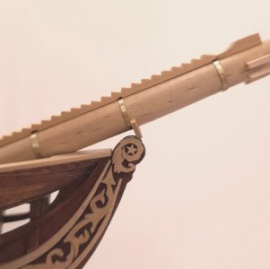
Three options suggest themselves.
1. Leave it alone (by far my favorite!)
2. Remake the fairlead and locate it further forward, say 3.15mm (1/8")
3. Lop off the locating tenon at the aft end of the bowsprit and drop that end lower to increase the angle slightly
and this was my third fairlead of the day. I had issues drilling the 10.5mm hole. That was resolved by setting up the drill press vs. drilling by hand.
Before making the fairlead and chocks, I wanted to see how much effort would be involved in rigging the gammoning "chain" (I opted for rope). It turned out not to be too much of a hassle. But, off it came to start adding the as yet unmade components.
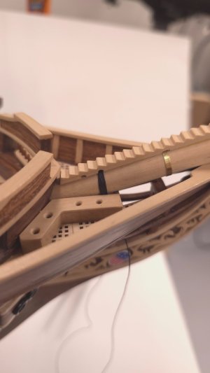
I did the prep work of determining the correct number of holes (7 according to MS plans. 8 according to Bob Hunt). 9 according to Marquardt.
Since Mustafa had seven, I opted for the "consensus" view).
Then I marked the boxwood blank and began fabrication. Drat! I don't have photos of the next steps! Well, if I choose option 2 above, I'll have a second chance at documenting the making of the fairlead...
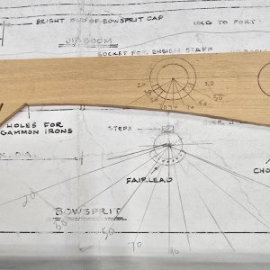
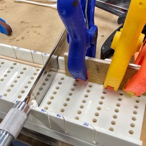
Note: for some things (like cutting the chocks to length), old school is still the best.
Everything confirmed to plan, yet the fairlead is sitting on the scrollwork.
Three options suggest themselves.
1. Leave it alone (by far my favorite!)
2. Remake the fairlead and locate it further forward, say 3.15mm (1/8")
3. Lop off the locating tenon at the aft end of the bowsprit and drop that end lower to increase the angle slightly
and this was my third fairlead of the day. I had issues drilling the 10.5mm hole. That was resolved by setting up the drill press vs. drilling by hand.
Before making the fairlead and chocks, I wanted to see how much effort would be involved in rigging the gammoning "chain" (I opted for rope). It turned out not to be too much of a hassle. But, off it came to start adding the as yet unmade components.
I did the prep work of determining the correct number of holes (7 according to MS plans. 8 according to Bob Hunt). 9 according to Marquardt.
Since Mustafa had seven, I opted for the "consensus" view).
Then I marked the boxwood blank and began fabrication. Drat! I don't have photos of the next steps! Well, if I choose option 2 above, I'll have a second chance at documenting the making of the fairlead...
Note: for some things (like cutting the chocks to length), old school is still the best.
Last edited:


Fabulous modeling Peter.
I know this feeling way too often- it’s the modeling gods I tell you….… Cheers GrantOh for Pete's sake... What happened here?
Everything confirmed to plan, yet the fairlead is sitting on the scrollwork.
2026 July 02: Fairlead fail corrected!
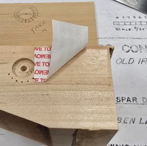
I chose option 2 above: Remake the fairlead and locate it further forward, say 3.15mm (1/8"). So, here’s the documentation on making the fairlead in excruciating detail. In case it’s unclear in the middle photo in the top row below, I used double sided tape to affix the boxwood blank onto a piece of scrap wood – thus I eliminate ragged edges on the flip side of the piece after drilling.
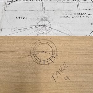
I used double sided tape to affix the 1.56mm basswood blank to a backing board - thus eliminating tear-out on the back side of the drilled holes.
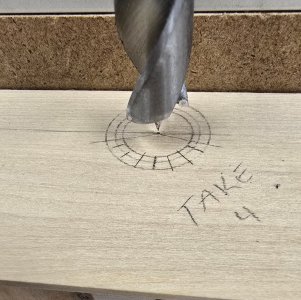
I tried this using a hand drill three times before figuring out there's a reason I got a drill press with fence.

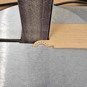
I used a piece of rolled up sandpaper to fine tune the inner arc on the fairlead.
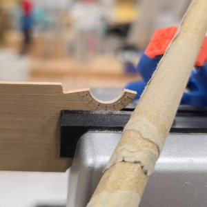
test fit...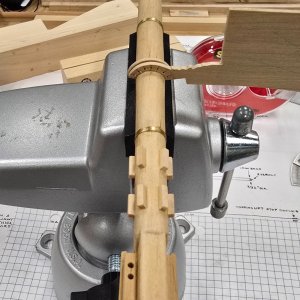
Fine tune the bulk of the fairlead (leaving the final trimming to good old fashioned sanding stick.
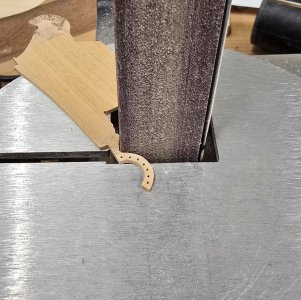
The old fairlead needed to be chiseled off.
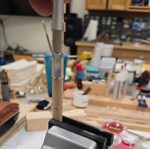
and here's the new fairlead in its new position.
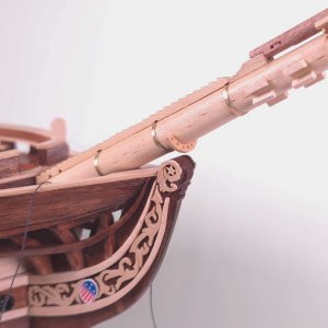
I chose option 2 above: Remake the fairlead and locate it further forward, say 3.15mm (1/8"). So, here’s the documentation on making the fairlead in excruciating detail. In case it’s unclear in the middle photo in the top row below, I used double sided tape to affix the boxwood blank onto a piece of scrap wood – thus I eliminate ragged edges on the flip side of the piece after drilling.
I used double sided tape to affix the 1.56mm basswood blank to a backing board - thus eliminating tear-out on the back side of the drilled holes.
I tried this using a hand drill three times before figuring out there's a reason I got a drill press with fence.
I used a piece of rolled up sandpaper to fine tune the inner arc on the fairlead.
test fit...
Fine tune the bulk of the fairlead (leaving the final trimming to good old fashioned sanding stick.
The old fairlead needed to be chiseled off.
and here's the new fairlead in its new position.

A nice solution, Peter. And I think the right one...


I love to follow your problem solving skills. Your Conny will be a masterpiece when finished. Great job!
2026 July 03: Jibboom and flying jibboom.
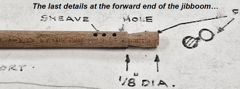
Nothing by way of process photos today. There were a couple of details needing attention on the jibboom. A sheave needed to be added at the forward end, as did a third hole. Also, the very end needed to be reshaped to accommodate the “iron” ring which will hold part of the flying jibboom. I’ve shown enough lathe work in shaping spars and mill work to simulate sheaves, that I didn’t bother with the details of the construction of the flying jibboom.
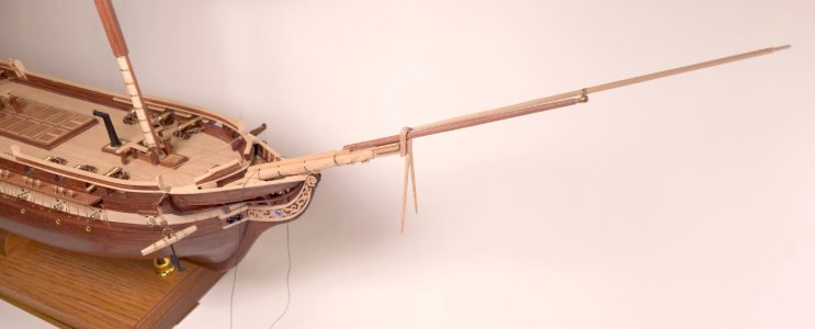
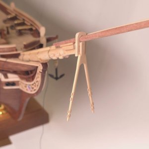
The flying jibboom should be the last item requiring lathe work on this model. Here it is attached to the jibboom and bowsprit cap. I got so wrapped up in the brasswork, that I forgot to take pictures of the flying jibboom irons – that connected double circle in the plan photo above. Basically, I just bent some brass strip around an 1/8” drill bit to get me the loops. Some tweaking with pliers, and the application of some 5-minute epoxy, was all that was required at that end. To affix the other end of the flying jibboom to the cap, I made a staple, drilled a couple of holes, applied some C/A glue and drove the staple home with a pair of pliers.
Here’s everything in place. The cap has not been glued in, so I can remove the jibboom, flying jibboom assembly to store it safely until I’m done rigging everything aft of the cap.
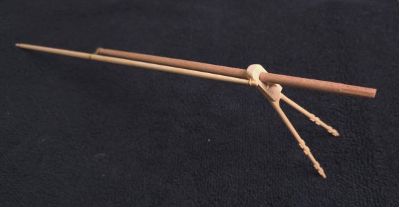
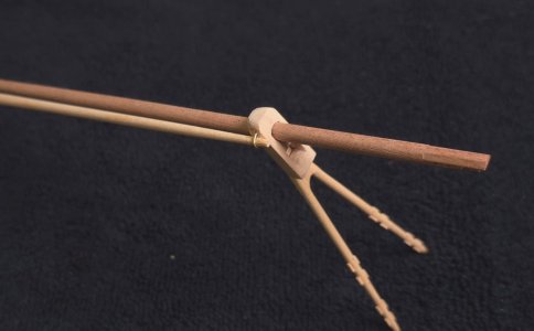
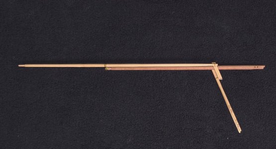
Nothing by way of process photos today. There were a couple of details needing attention on the jibboom. A sheave needed to be added at the forward end, as did a third hole. Also, the very end needed to be reshaped to accommodate the “iron” ring which will hold part of the flying jibboom. I’ve shown enough lathe work in shaping spars and mill work to simulate sheaves, that I didn’t bother with the details of the construction of the flying jibboom.
The flying jibboom should be the last item requiring lathe work on this model. Here it is attached to the jibboom and bowsprit cap. I got so wrapped up in the brasswork, that I forgot to take pictures of the flying jibboom irons – that connected double circle in the plan photo above. Basically, I just bent some brass strip around an 1/8” drill bit to get me the loops. Some tweaking with pliers, and the application of some 5-minute epoxy, was all that was required at that end. To affix the other end of the flying jibboom to the cap, I made a staple, drilled a couple of holes, applied some C/A glue and drove the staple home with a pair of pliers.
Here’s everything in place. The cap has not been glued in, so I can remove the jibboom, flying jibboom assembly to store it safely until I’m done rigging everything aft of the cap.
Exquisite modeling, Peter. That wishbone is pretty impressive - best to put it away for safe keeping!


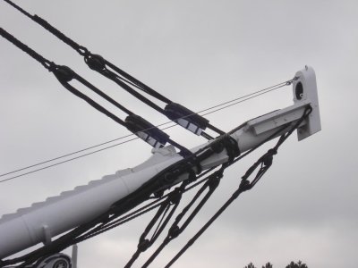
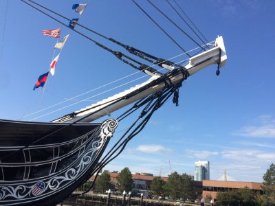
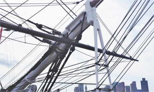
Thanks Jon,
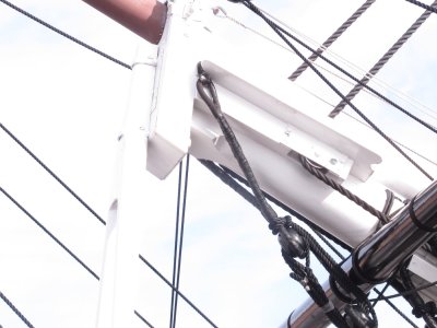
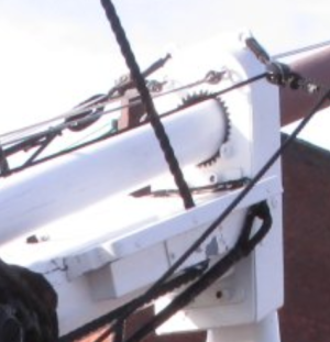
What exactly is happening at the forward end of the bees in the first photo? I thought that was an eyebolt, but closer inspection suggests otherwise. Got a picture of the upper face of the bees?
What exactly is happening at the forward end of the bees in the first photo? I thought that was an eyebolt, but closer inspection suggests otherwise. Got a picture of the upper face of the bees?
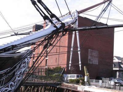

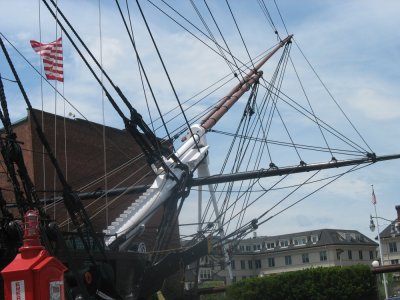

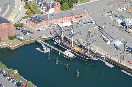

So, not a pair of eyebolts after all.
Just a small section of chain? connecting the bobstays? At least now I know what the indentations at the forward end of the bees are for.
Also interesting to note the different numbers of ropes passing through the fairleads in the 2nd and 3rd photos.
Just a small section of chain? connecting the bobstays? At least now I know what the indentations at the forward end of the bees are for.
Also interesting to note the different numbers of ropes passing through the fairleads in the 2nd and 3rd photos.

- Joined
- Oct 9, 2020
- Messages
- 2,549
- Points
- 538

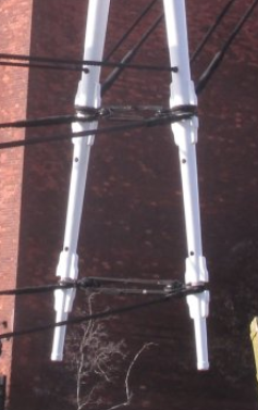
In regards to the dolphin striker, it seems that we have a number of holes to drill, and I see them in the photo of the actual one, but only the top holes are used. I wonder what the purpose of the other holes are. I am tempted to not even drill those bottom holes especially since the bottom part of the striker is so fragile.
Last edited:
Every time I have that thought, and express it here, someone posts a photo showing exactly where that hole, or sheave, or eyebolt is being used. Better to have it and not need it, then need it and not have it. For what it's worth, if you used boxwood to make the striker, you wouldn't have concerns. It's pretty sturdy stuff.


- Joined
- Oct 9, 2020
- Messages
- 2,549
- Points
- 538
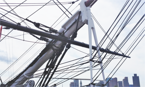
I don't get it. One pic they are 't used and another they are. Anyways, I'll drill them.This is in Jon's first set of photos, and all three of the dolphin striker's holes appear to be occupied.
View attachment 616859
2026 July 10: Experimenting with XKen’s brass “iron” work.
In order to attach the jibbooms to the yards, I’ll need to learn how to make the “irons” that will be mounted to the yards. Here are two excerpts from Ken’s build log illustrating the goal.
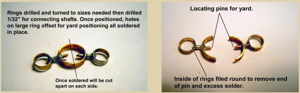
Here’s my proof of concept attempt…
I was able to find some brass tubing with inside diameters close to those I’ll need for the yards and jibbooms. If I have to, I suppose I can drill out the center of some solid round stock after turning it to the appropriate outside diameters. But maybe I’ll get lucky and not have to go that route. For the main mast yard and jibboom, I seem to be covered. After selecting the drill closest to, but slightly larger than the 0.60mm brass rod I have on hand, I drilled holes into the brass tubes. Here’s the larger tube for the yard. I got a bit sloppy, and drilled one side too close to the end of the tube, so can’t exactly duplicate Ken’s example.
(Paul, you jumped in too quickly! I never get these posts right the first time. Here are the missing photos)
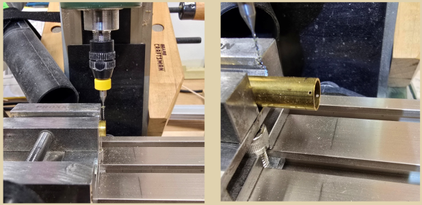
Next, slice off the end, centering the hole on the rim…
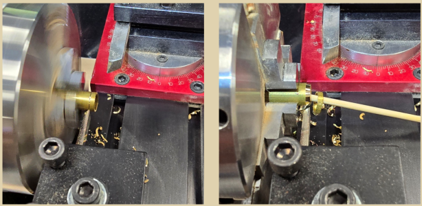
Then to make use of my new RSU (resistance soldering unit) from American Beauty, I set up to do the soldering. This proved to be much more difficult than these photos suggest. Those pinpoints on the soldering tweezers are difficult to position unless everything is held solidly in place.
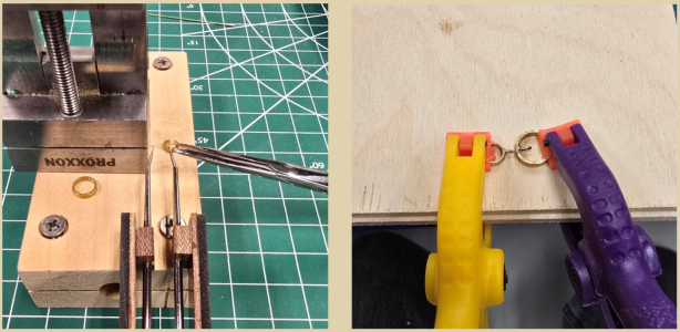
The photo (above right), looks pretty good, eh? It wasn’t until I removed the clamps that I saw that the plastic melted from the soldering. I’m going to have to find a better way, or go through a bunch of these clamps to get the job done.
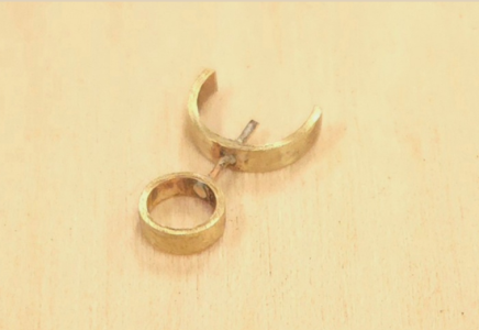
After some tweaking with files and emery cloth, here’s the result. The diameter of the smaller cylinder is about a .165mm larger than that of the jibboom it will receive. That’s perfectly good. Likewise, the diameter of the half-pike (did I spend too much time watching the Winter Olympics last year?) will fit the yard nicely. The pin should make placement easier. We shall see.
P.S. If anyone is wondering what the RGB values for the background color are here, they are:
R 224
G 210
B 175
I changed the "Page Color" under Design in Word to those values before I pulled screen shots to insert here. Plugging in those values matched SoS's background color perfectly. (Update 4, if you're keeping count, Paul - um, make that 5. Yeech!
  )
)
In order to attach the jibbooms to the yards, I’ll need to learn how to make the “irons” that will be mounted to the yards. Here are two excerpts from Ken’s build log illustrating the goal.
Here’s my proof of concept attempt…
I was able to find some brass tubing with inside diameters close to those I’ll need for the yards and jibbooms. If I have to, I suppose I can drill out the center of some solid round stock after turning it to the appropriate outside diameters. But maybe I’ll get lucky and not have to go that route. For the main mast yard and jibboom, I seem to be covered. After selecting the drill closest to, but slightly larger than the 0.60mm brass rod I have on hand, I drilled holes into the brass tubes. Here’s the larger tube for the yard. I got a bit sloppy, and drilled one side too close to the end of the tube, so can’t exactly duplicate Ken’s example.
(Paul, you jumped in too quickly! I never get these posts right the first time. Here are the missing photos)
Next, slice off the end, centering the hole on the rim…
Then to make use of my new RSU (resistance soldering unit) from American Beauty, I set up to do the soldering. This proved to be much more difficult than these photos suggest. Those pinpoints on the soldering tweezers are difficult to position unless everything is held solidly in place.
The photo (above right), looks pretty good, eh? It wasn’t until I removed the clamps that I saw that the plastic melted from the soldering. I’m going to have to find a better way, or go through a bunch of these clamps to get the job done.
After some tweaking with files and emery cloth, here’s the result. The diameter of the smaller cylinder is about a .165mm larger than that of the jibboom it will receive. That’s perfectly good. Likewise, the diameter of the half-pike (did I spend too much time watching the Winter Olympics last year?) will fit the yard nicely. The pin should make placement easier. We shall see.
P.S. If anyone is wondering what the RGB values for the background color are here, they are:
R 224
G 210
B 175
I changed the "Page Color" under Design in Word to those values before I pulled screen shots to insert here. Plugging in those values matched SoS's background color perfectly. (Update 4, if you're keeping count, Paul
- um, make that 5. Yeech! )
Last edited:

Excellent work, Peter! Ken is OBVIOUSLY the king of all-things brass, so you can't go wrong following his lead.
I have done horribly in my past RSU soldering efforts, so I gave it up. But may give it another whirl when the time comes. To my credit, though, I never melted any plastic from my clamps... <shrug> I do like, though, how you used the Proxxon vise to hold the pieces to solder. It can take the heat much better than the clamps.
Nice work overall, Peter. Continuing to watch!
I have done horribly in my past RSU soldering efforts, so I gave it up. But may give it another whirl when the time comes. To my credit, though, I never melted any plastic from my clamps... <shrug>
I do like, though, how you used the Proxxon vise to hold the pieces to solder. It can take the heat much better than the clamps.Nice work overall, Peter. Continuing to watch!

- Joined
- May 10, 2026
- Messages
- 18
- Points
- 13

I am just completing my first kit (OcCre's HMS Beagle) which has come out quite nicely. I have experience with plastic models from my childhood, but nothing since, and never in wood, though I am a somewhat experienced woodworker. I am very interested in following your and others' build logs as I move to my next kit- the MS USS Constitution. I would prefer to build her as her roughly 1812 version. Can anyone direct me to a good log or other instruction in doing so? Thanks in advance!I'm one of the current refugees from ModelShipWorld.com. I'm about three years into the build, and while my build log from the now hosed site is likewise hosed, I have been keeping my own personal build log on my desktop PC. I'm trying to decide if I post my build log here going forward. And if so, is it worthwhile for me to upload the 200 plus hundreds pages from my pdf files here, or whether I just start the log from where I stand today. Some friends and builders I've come to know well at MSW also post here, so I'm thinking I might follow suit.
My work flow has been that when I work on Connie, I take photos on my phone, from there I've uploaded them to the MSW site and posted that day's log. When I get home, I copy the pictures and text from that build log and add them to my personal log. Right now I'm a little behind, in that I'm a about a month behind from where I left off at MSW. I'll have to see if I can use the same workflow for this site that I used there, though I feel that I probably can. Then it's a matter of how far back I go in posting my build here.
Stay tuned?