• Ships of Scale has incorportated an extra level of security when you log In. Please follow on-screen prompts to acknowledge that you are not a robot via a "Check Box" or a "Pictorial Check Box Puzzle". This is needed due to higher level of AI Activity Security.
  • SUBSCRIBE TO SHIPS IN SCALE TODAY!

    The beloved Ships in Scale Magazine is back and charting a new course for 2026!
    Discover new skills, new techniques, and new inspirations in every issue.

    NOTE THAT OUR NEXT ISSUE WILL BE July/August 2026
  • Win a Free Custom Engraved Brass Coin!!!
    As a way to introduce our brass coins to the community, we will raffle off a free coin during the month of August. Follow link ABOVE for instructions for entering.

USCG Harriet Lane - Model Shipways 1:96 by DocTom

Post 16 - Some Answers

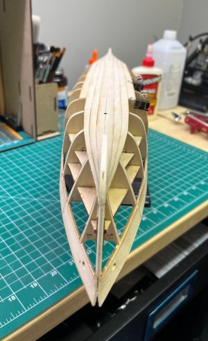
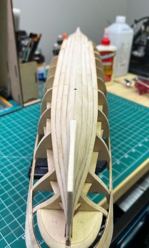
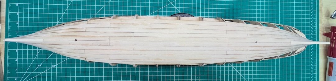
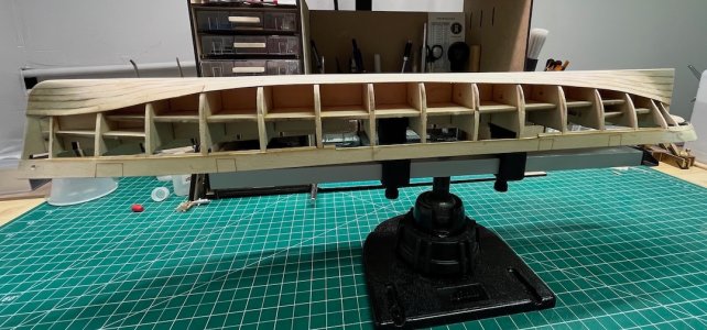
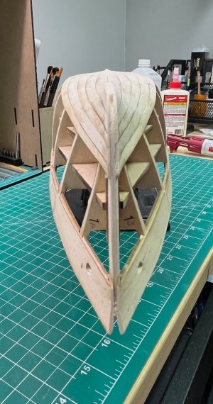
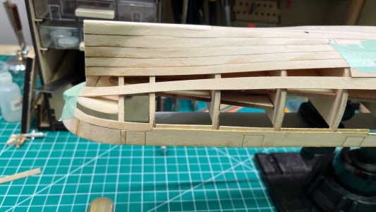
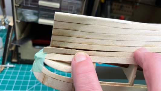
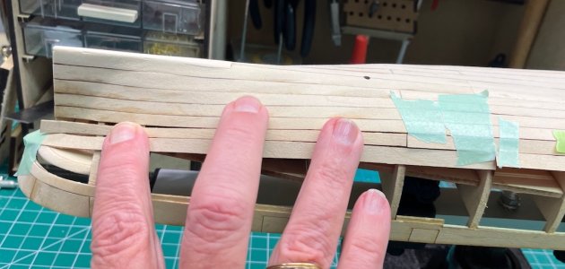
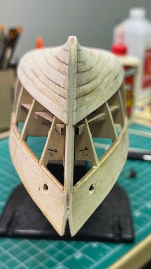
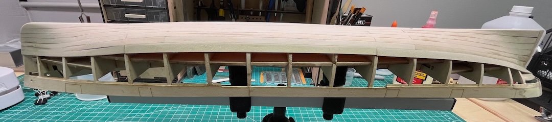
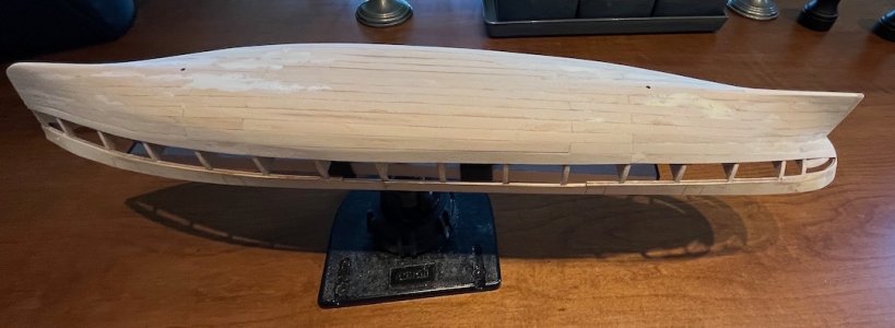
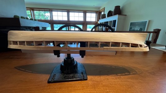
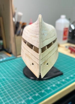
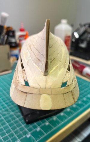
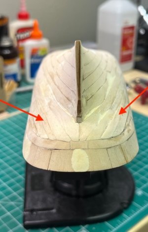
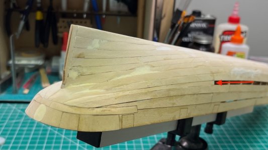
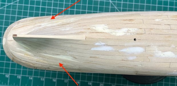
Strake 3 and 2/3 of strake 4 are now on. I've settled into a rhythm of fit and bend the aft pieces, glue them on, while they're drying fit and bend the center pieces, etc. Strakes 3 and 4 are not nearly as oversized as #2, just a few mm at each end. I decided to trim the front pieces where they meet the center pieces, which I now know was the wrong choice (more of that below). Harriet currently looks like this:
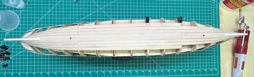
3.66 strakes.jpeg

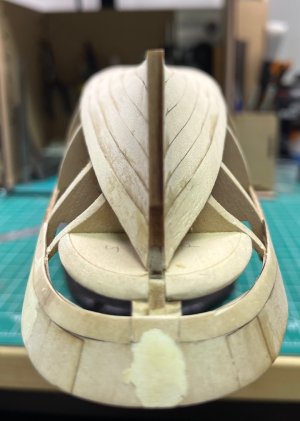
Eying down the bow.jpeg not too bad.jpeg

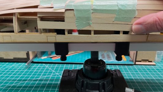
The two sides are pretty even at the stern
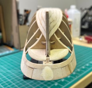
Even at the stern.jpeg

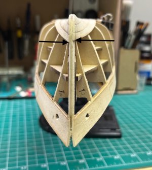
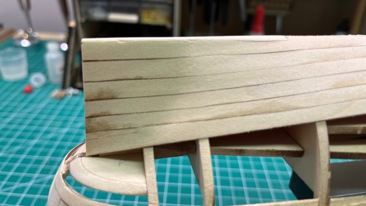
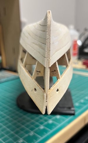
but not at the bow
Off at the bow.jpeg

After I closed up the shipyard for the day I saw a response to my question of yesterday on DDM from someone who has built the Harriet Lane, and lost his build log in the MSW crash. He mentioned that all the bow port planks were wider than the starboard bow planks on his model. I clearly have the same issue. He reduced the port planks to match the starboard ones. I think reversing the port and starboard 4 and (maybe) 5 planks will even me out, and then I can shape the rest to be equal.

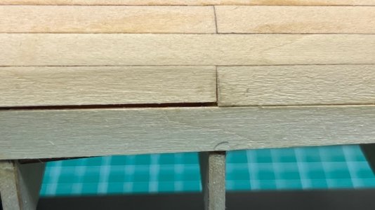
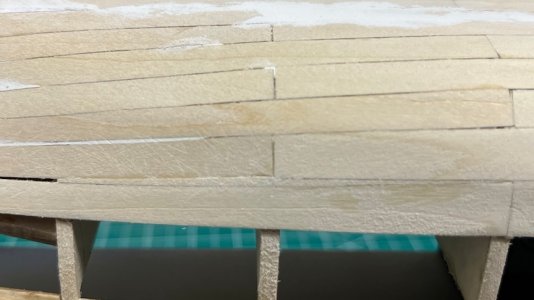
He also recommended trimming the excess off the planks at the bow and stern, so the width midships is equal. In retrospect I should have come to the same conclusion, because trimming the back end of the bow planks has made them thinner than the front end of the central planks, and the subsequent gap will need to be filled.

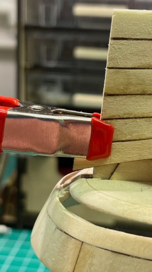
Overall the planking is going fairly easily. I sand the bevels on the abutting edge before I bend the plank. I bend the planks by wetting them briefly, clamping the bow or stern end, and using my planking iron to coax them into shape on the hull. This lets me adjust things as I go and has the advantage of drying the plank quickly so I can glue it almost immediately, without waiting for it to dry on its own. I make final adjustments with sanding sticks before applying glue. I have been gluing from 2-3 bulkheads at a time, working from the bow or stern inward. The central planks have needed minimal shaping so far.

There is one other potential planking issue. The instructions clearly show that strake 6 should fit against the bottom of the knuckle piece at the stern. Based on where the planks sit after strake 4, that is clearly not going to happen. Strake 7 is designed to lie against the knuckle. I will need to figure out how to deal with the gap.

So the answer to my question in Post 15 is to trim at the bow (or stern). In addition I have relearned the need to check that supposedly symmetrical parts are really symmetrical before you glue them on. Two good lessons!
 
For what it's worth, I trimmed mine at the back end to reserve the slant of the planking at the bow.
 
Post 12 - Mail Call

I have glued on 18 of the 32 required bulwark inner filling strips, but the exciting news is that this arrived in the mail today, direct from Ebay:

The whole process is very old-fashioned. You need the paper catalog to see which plans are available, and you need to send a check or money order (really?) by snail mail. No PayPal, credit cards or ordering online.
Tom, this is a really cool resource (despite it being stuck in the stone age LOL). Nice find! As you said, I hope the plans are above and beyond that of kit content.

Your model is looking great!
 
Post 15 - A Question
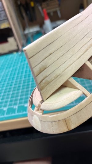
I've finished off the bow and stern ends of the garboards, and started on the 2nd strake. I began at the stern, as the aft piece lined up almost perfectly with the middle of a bulkhead, as did the central piece. This leaves a significant amount of excess plank at the bow. Should I trim it at the back end where it meets the central piece
View attachment 622627
or at the bow?
View attachment 622628

I'm thinking at the back end, to preserve the taper of the plank as it nears the bow, but if anyone who's built this model has any thoughts, I'd appreciate your wisdom.
Fielder’s choice on where to cut. How about a small block glued on the bulkhead where the plank meets it for a bit of support?

Challenges have been handled deftly. Enjoying the work. BZ.
 
Post 17 - Planking, Part 3

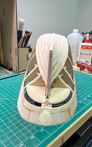
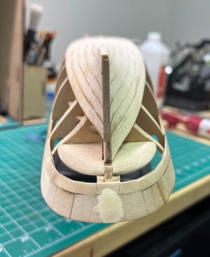
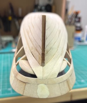
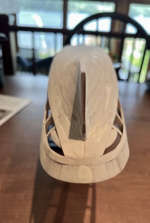
Strakes 4 and 5 are now on. I had to do some more fairing of bulkhead 11, and add a shim to the port side of bulkheads 7 and 5 to keep everything even and flowing relatively smoothly. My port side 1-4 fore planks are indeed wider than the starboard ones. Plank 5 is the same on both sides! I reversed the port and starboard 4 fore planks, which evened things out somewhat, but not completely. I've also done some preliminary sanding so I have a sense of where I will need filler.
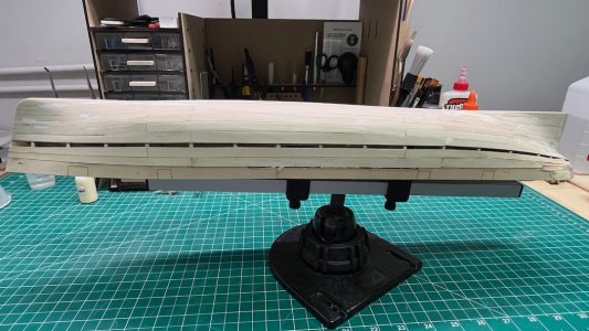
It's starting to look like a hull.
5 strakes.jpeg
Side view of 5 strakes.jpeg
Bow view 5.jpeg Stern View 5 B.jpeg

I've also bent the aft plank 6, which brings me to the next problem I have to solve. The aft end of plank 6 is designed to touch the stern knuckle. Mine will not, as you can see here:
The problem.jpeg

My initial measurement shows I am 4 mm shy. I'm still not sure how to address this. My current thinking is to make a wider set of the #6 strakes. I can use the current strakes for a guide. I could also add an additional strake, but I'm not sure how I would shape it. The third option is to attach strake 6 where it should be, and then spline a plank to fit between 5 & 6, but I'm not sure how I would determine where strake 6 should lie (maybe just 4 mm below strake 5 everywhere?). Option 4 is to start planking down from the bulwarks and then fashion a plank to fill the gap between 7 & 6, but I don't think I can shape 7 without the adjoining plank in place. Any advice would be greatly appreciated!
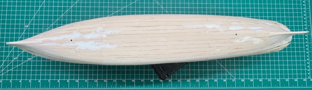
 
If I remember correctly, I also had to add additional planking to fill in the gaps. Since I then put wood filler over the entire hull, sanded it down and painted it, you do not see these additional planks.
 
Post 18 - Planking Part Part 4 and Some Interesting Mail

In order to figure out how to deal with the mis-aligned strake 6, I did a test by temporarily taping the central pieces of strakes 6 and 7 to the hull. When I lined up the aft piece of Strake 7 with the center piece it fell very naturally to the knuckle.
IMG_5665.jpeg
When i laid in #6, it became obvious that what I need is a stealer:
IMG_5664.jpeg

I also taped on the remaining center pieces. It is as I suspected: the planks aren't wide enough to cover the hull. I will need to add an extra plank, probably between 9 and 10.
IMG_5666.jpeg

Instead of making a stealer I just made a wider plank 6, after I figured out how big the stealer should be. You can see the line on the plank where I added the extra height (or depth, since it's upside down).
IMG_5670.jpeg
IMG_5672.jpeg IMG_5671.jpeg
That felt like I did something good!

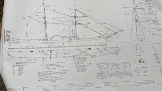
My mail today included a tube from the Smithsonian Institution containing War Ship Plan 563 - The Harriet Lane!
Rigging Plan.jpeg
Drawn in 1964 by Merritt Edson. It's basically a rigging plan and unfortunately doesn't give any info about whether there was a pivot gun forward of the foremast or where and how many lifeboats she had in 1858. It does show the wheel at the very stern. It has measurements for the spars, and sizes for the chains and various rigging lines. It may be useful if I decide to do more advanced rigging than Model Expo includes (although it's hard to know how historically accurate it is).

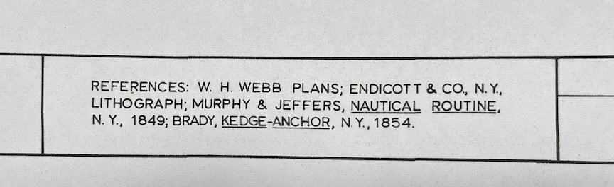
It also has an intriguing citation:
Maybe the original plans?.jpeg
I'm going to try to track them down.

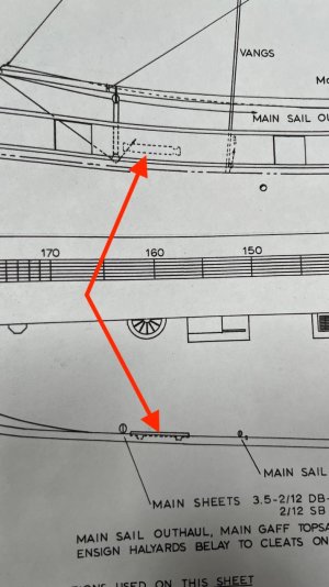
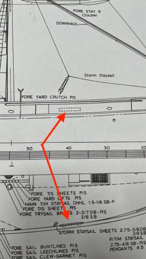
A question for the group. Does anyone know what these elements on the bulwarks are? There's one fore and aft.
Mystery Structures.jpeg
Mystery 2.jpeg

IMG_5663.jpeg
 
As you continue the planking, remember to keep the slot for the paddlewheel sponson and not fill it in like I did. In your last photo, one end of the slot is located just above the rightmost gunport. Could the mystery object be a rack of belaying pins?
 
Hey Tom, lookin' good! As for that mystery feature, a quick Copilot visual search yielded the following. New to me if accurate!

It is the sheet lead location for the storm staysail — the point on deck where the storm staysail’s sheets run or are belayed.

And it created this illustration - seems to make sense?

Copilot_20260804_091022.png
 
Hey Tom, lookin' good! As for that mystery feature, a quick Copilot visual search yielded the following. New to me if accurate!

It is the sheet lead location for the storm staysail — the point on deck where the storm staysail’s sheets run or are belayed.

And it created this illustration - seems to make sense?

View attachment 624062
Maybe, but the plan shows a block for the storm staysail sheets just aft of it.
 
Post 19 - Planking Part 5

The remaining pieces of strake 6, and strake 7 were added over the past 3 days. I again made a new aft piece of the starboard strake 6 to fill the gap to the stern knuckle (only 3 mm on this side).
6 strakes stern view.jpeg

I have been doing some sanding as I go along, which is showing the areas where I will need some filler.
Going has been slow as the stern pieces of # 7 required a lot of shaping to fit. Ideally they should be edge bent, but the preformed pieces are too wide to do that (I tried). I hope this is the last hull I plank with preformed planks! I reversed the port and starboard sides of the front pieces of 6 and 7, and the bow is now fairly even:
7 Strakes bow view.jpeg
I will alternately reverse the fore pieces on the remaining strakes to try and keep them even.
Some other views:

7 strakes bottom view.jpeg
7 strakes side view.jpeg
I purposely left a gap at the bow end of #7 to even out some of the waviness.

I also added the aft piece of strake 8. It also should have been edge bent. I ended up doing a lot of sanding to shape the edge abutting #7. The curves at the stern now begin to ease off, so I hope the remaining strakes will go faster.
7 strakes stern vie.jpeg

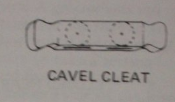
I posted my query about the mystery objects on the plans I obtained from the Smithsonian Institution. Several members pointed out that they are cavels, large cleats mounted to the bulwarks for the mainsail sheets and mooring lines.
1785890709479.png

I'm hoping my next post will show a completely planked hull!
 
Last edited:
Post 20 - Planking Part 6 (part 6, really? This is going way too slowly!)

I'm managing about 1 strake every 2 days lately, a combination of too many summer distractions here in the Berkshires and my mounting frustrations with the preformed planks provided by Model Shipways. I have now completed the 8th strake. One issue is that the ends of the forward, central and aft planks aren't the same width, leading to gaps:
Issue with preformed planks.jpeg
I've filled some of them with stealers
Filler piece.jpeg
and some I plan to fill some with Durham's putty. I did some preliminary filling and sanding at the stern. Harriet had her first excursion outside for the sanding session. Here's how she stands today:
8 plank bow.jpeg
prelim filler stern.jpeg
8 strake hull.jpeg
8 strake side view.jpeg

You can see one of my major distractions - the Stockbridge Bowl - in the background.
Clearly more filling and sanding is needed. There are two strakes left. I will clearly need to add a third of my own. My plan is to attach the 10th strake below the bulwarks (as it is clearly designed to go there) and then decide if I should put the filler strake between 8 and 9 or 9 and 10, depending on where 9 lies the most naturally.

I've been thinking about the deck. UPS delivered possible decking planks today. deck planking?.jpeg
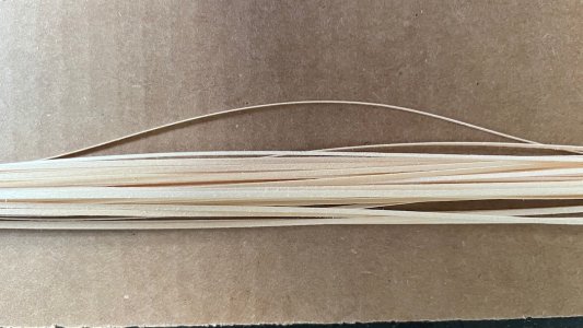
They are basswood, from Northeastern Scale Lumber, an outfit that seems to mainly cater to the model railroad community. Very reaonably priced. They are claimed to be only 0.012" (1/83rd inch) thick. 1/16" (scale 6') wide. I'm hoping they will let me plank the deck without messing up the location of the guns in the gun ports. I'll have to see if I can work with such thin planks.
 
Post 21 - Planking Part 7

It's almost done! I added Strake 10, and decided Strake 9 worked best adjacent to it, leaving the gap between 8 & 9. As always, the stern was the challenge, and the preformed planks required significant shaping to get them to fit. I continued to bend them with heat and a little moisture added with my finger, rather than soaking the entire plank. The planking is not as tight as earlier, but that's why I have Durhams putty!
Strake 9 & 10 bow.jpeg Strake 9 & 10 stern.jpeg
Strake 9 & 10 side.jpeg
Strake 9 & 10 top.jpeg

I had raised the bulwarks to correct the issue of too low gun ports (see Post 9), so I expected a gap. The gap measures 11/64 most places. I raised the bulwarks 6/64, so I would have had a gap no matter what. I spiled the two planks using the masking tape and compass method Toni Levine describes in the NRG Half-Hull Project (David Antscherl does the same with card stock and a compass in his NRG planking tutorial). It worked out fairly well, considering this was the first time I had done this.

Spiled stern.jpeg
Spiled 3:4 view.jpeg
Spiled Top view.jpeg


I'm hoping to finish the planking tomorrow, so I can show a filled and sanded hull with my next post.

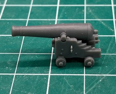
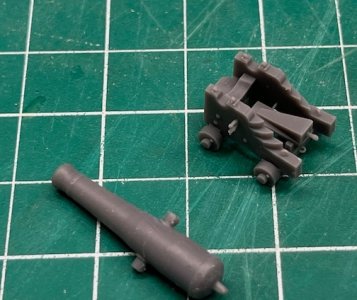
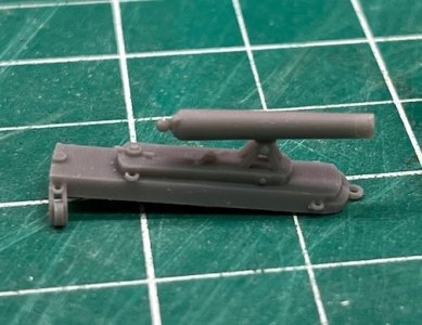
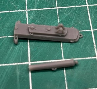
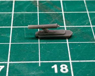
The Post Office recently delivered some 3D printed guns to my PO Box (we live in a quaint New England small town where they don't deliver the mail - you need to go to the post office to pick it up and gossip with the neighbors). I had downloaded the .SML files @JerryTodd has graciously made available on Thingiverse. I don't have access to a 3D printer, so I found someone on Etsy to print them for me. I am building the Harriet Lane as she looked when launched. The USCG historian says she was armed with a 32 pounder pivot gun
3D 32 pounder.jpeg 32 pounder pieces.jpeg
(I'm still not sure how a pivot gun will fit on the deck as published by Webb so I bought the 32 pounder itself); four 24 pounder Howitzers
24 pounder howitzer.jpeg Howitzer pieces.jpeg

and a 12 pound boat howitzer
12 pounder boat howitzer.jpeg

The guy who printed them for me couldn't do the extension screws (too thin at this scale he said). I may fashion them from wire, or try someone else to print them.

That's it for now.
 
Tom, your planking is looking very nice. You are putting a lot of time and consideration into it. As for the 3D printing you may want to see if your local library has one. My library has a Bambu 3D printer as well as a laser engraver. I have used to laser to make plaques for my models. I am currently using the library printer to make a rope walk one of our other members has been kind enough to share. They charge me $2 an hour and throw in the filament.

Rob
 
Tom,
According to the book, U.S.C.G. and Revenue Cutters, 1790--1935, at launch in June 1861 she had 3- 32 pounders and 4- 24 pounders but in Feb. 1862 she had 3- 9 inchers and 1- 30 pounder rifle. Not sure that there was a pivot system on the first iteration of the ship. Also, looking at Webb's plan the paddlewheel has twenty floats not the lesser amount the kit provides and the wheel rims were thinner, being metal, but you probably have discovered this through other people interested in your build. I'm getting ready to start this build and plan to plank to scale with 1/64th veneer over the kit planking (which is much too wide), after a slight sanding down to keep the hull to scale. Cheers.... really like what you are accomplishing.
 
Tom,
According to the book, U.S.C.G. and Revenue Cutters, 1790--1935, at launch in June 1861 she had 3- 32 pounders and 4- 24 pounders but in Feb. 1862 she had 3- 9 inchers and 1- 30 pounder rifle.
Thanks for the kind words. The planking has taken far longer than I thought. I know the preformed planks are designed to make it easier, but after my 4th model with them, I think they just make it harder. Your idea of veneer is intriguing, but since I'm planning to copper plate the lower hull I'm hoping a good filling and sanding will make the rest look OK.

I think the info in Canney's book is incomplete (I have the book). Remember, the Harriet Lane was launched in 1857, not 1861. 1861 is when she became a US Navy vessel. The USCG History webpage on the Harriet Lane states she was launched on 19 November 1857 and comissioned on 28 February 1858. They list her armamanent as:
Armament:
1858: 1 x 32-pdr pivot gun; 4 x 24-pdrs; 1 x 12-pdr
1861 (1 June): 3 x 32-pdrs; 4 x 24pdrs
1862 (Feb): 3 x 9”; 1 x 30-pdr

However, the Harriet Lane is notorious for being poorly documented. I agree the published plans make it hard to see how a pivot gun fit on the deck.

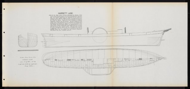
Do you have a plan by Webb that shows the paddle wheels? The only plan of the Harriet Lane actually drawn by William Webb that I know of is this:
IMG_0291.jpeg

which obviously has no info about the paddle wheels. It would be great if you've found more detailed plans.

Hope you post a build log when you're ready to start.

Tom
 
Post 22 - Planking Part 8 - Finished!

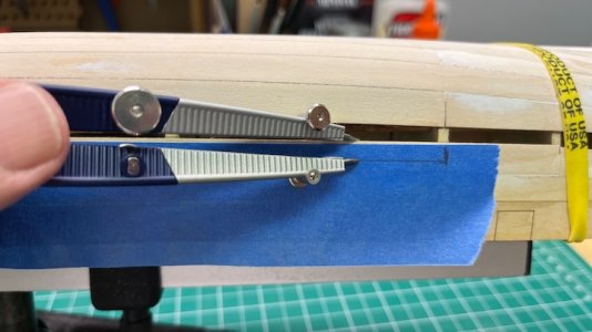
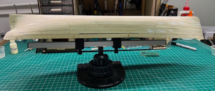
After spiling the remaining filler planks, Harriet's hull is now completely covered. It only took 18 days! For anyone following who doesn't know the spiling technique described by Toni Levine and David Antscherl, it's fairly easy. First, place a piece of masking tape (or paper stock) on the plank whose edge you need to replicate. Use a compass set to a convenient width to trace the edge of the plank on the tape:

Spiling 1.jpeg
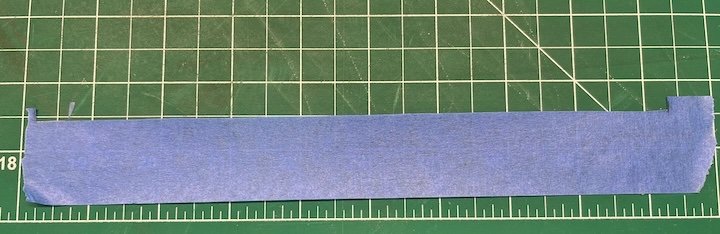
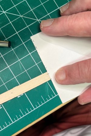
Mark the location of one edge of the bulkheads on the tape, and then place it on your cutting mat and cut along the line. I did it freehand with a #11 blade
Spiling 2.jpeg
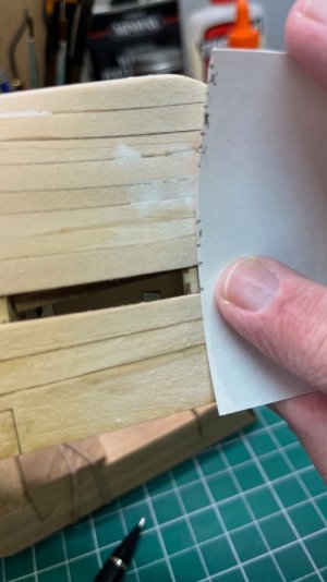
Put the tape on a piece of wood, trace the edge and then cut the wood along it. With a little sanding this will fit against the plank in place. Then use a piece of card stock (I used an index card) to measure the gap between the two planks at each bulkhead
Spiling 3.jpeg
and transfer it to the wood
Spiling 4.jpeg
connect the dots, cut along the resulting line, and with a little more sanding you have a plank that fits perfectly in place (almost):
Spiling 5.jpeg
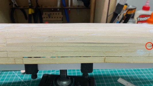
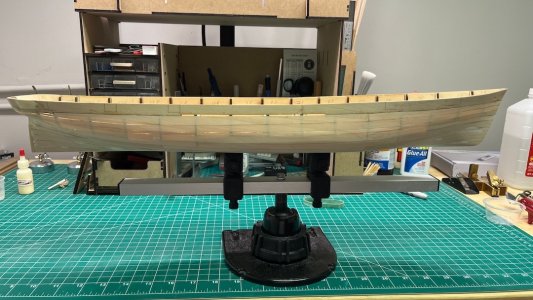
I cut the planks freehand as well. Go slowly and not too much pressure with a fresh blade. You can see my knife slipped at the very end. That's why God invented filler :oops: I had to put a couple of shims on bulkheads 7, 8 & 9 to get this plank flush. I should have used this technique to plank the entire hull. The preformed planks are supposed to make it easier, but there is so much variation in how everyone fairs their hull (and with Model Shipways so much variation in plank sizes) that I think they end up making it more challenging. However, she is now fully planked, front and back:
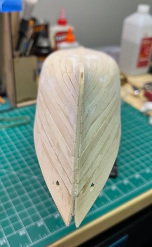
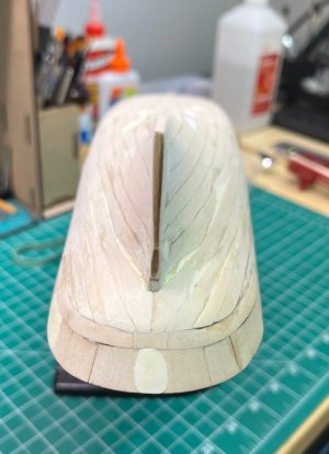
Planked bow.jpeg Planked stern.jpeg
port and starboard:
Planked port.jpegPlanked starboard.jpeg
bottom:
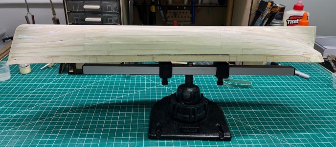
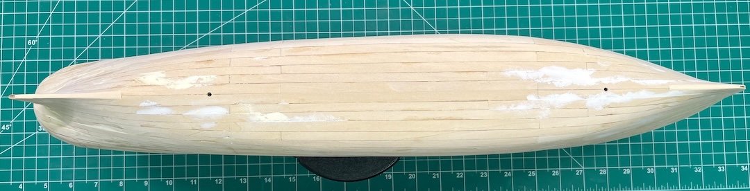
Planked bottom.jpeg
and finally out of Poseidon Adventure mode!

Upright!.jpeg
Now on to the filling (you can see the gaps) and sanding. I've done some already so I hope it won't take another 18 days. The instructions call this a marathon, and it was. But incredibly rewarding when I saw her in her fully-planked glory!
 
I have been following your post with great interest, I am in the last stages of my build on the Lane. I had a lot of the same issues you encountered with the planking the "planks" that were suppose to fit. You did much of the same problems solving as I did which also included some additional planks to complete. I am building straight from the instructions and did a painted hull so my mistakes and fillers were covered up with a couple of coats of copper. As I say "good enough for who it's for". Good luck on the rest of your build as I will enjoy seeing how it turns out for you.
 
Back
Top