• Ships of Scale has incorportated an extra level of security when you log In. Please follow on-screen prompts to acknowledge that you are not a robot via a "Check Box" or a "Pictorial Check Box Puzzle". This is needed due to higher level of AI Activity Security.
  • SUBSCRIBE TO SHIPS IN SCALE TODAY!

    The beloved Ships in Scale Magazine is back and charting a new course for 2026!
    Discover new skills, new techniques, and new inspirations in every issue.

    NOTE THAT OUR NEXT ISSUE WILL BE July/August 2026
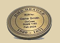
  • Win a Free Custom Engraved Brass Coin!!!
    As a way to introduce our brass coins to the community, we will raffle off a free coin during the month of August. Follow link ABOVE for instructions for entering.

His Majesty's Ship Fowey (44) 1744 by AllanKP69

Allan, since, this is a commission, I assume that time is money. Therefore, for the frames that will be planked over, why not use the Hahn method of assembling two ply blanks from mitered straight pieces and then cutting to shape with your scroll saw?
Too late, :) I have more than half the frames made. I did try the Hahn method 20 years ago. I doubt I would ever use it again. Unnecessary waste of materials IMHO
Allan
 
I haven't had time to read through this entire thread, but it's on my "must do" list. While everybody else is offering suggestions, I'll add a thought.

The electrostatic copying process (Xeroxing) consists of transferring a "meltable" powder onto a sheet of paper which is then heated to melt the powder in place, forming the letters or other image. Most copiers have a "density" or "darkness" setting that regulates the amount of powder applied to the paper.

A electrostatic copy may be easily transferred to another surface by placing the page face down on the surface to which you want to copy it and heating the back of the page with an iron. The heat again melts the powder melted on the copy and it sticks to the surface you want to transfer it to, creating an exact reverse image of what was on the original copy. While I've yet had occasion to use this process in transferring patterns to wooden workpieces such as frames and timbers, I see no reason why it shouldn't work. Simple as the process is, experimenting with the process in this application shouldn't be much of a bother and promises to eliminate a lot of the trouble gluing paper patterns to the wood for cutting out frames and timbers. Of course, if you don't have a means of easily reversing your original pattern, you need only to remember that you are cutting out the pattern in reverse, i.e., from the back side of the piece you are making.

If you try it and you like it, let us know! :)
 
Thanks Bob,
As the siding varies for floors, middle futtocks and top timbers the problem I foresee is that I would have to draw the frame, save each floor and futtock as a separate drawing block then gather the appropriate blocks on another drawing and arrange them to maximize wood usage, then heat transfer them to the appropriately thicknessed board. As the frames are all drawn and 70% made at this stage I am OK with the label paper for the rest of the project, but I will give it a try to see how it compares. Back to you sooner than later....
Allan
 
Bob, I gave up. As a target, I used my method of printing on label paper first. To print a frame on a sheet of label paper then slice each part of the frame from the sheet and stick it on a piece of wood timed out at just under 10 minutes. To redraw every frame to have all the pieces separate so I can transfer the ink onto the sheets of various thickness wood was long. I quit after redrawing took 15 minutes for one frame and that did not include printing and transferring onto the wood. I did try a hot rub to see how the ink transfers and it was a mess. First the iron was too cold, then too hot. The paper moved and was ruined. The lines were not nearly as clear as using label paper. Thanks for the suggestion though, I really appreciate your input. Maybe I did it all wrong, but it did not work for me. As it works for you could you please post a tutorial with pics. It would be a great addition to the Tricks of the Trade subject here at SoS.
Allan

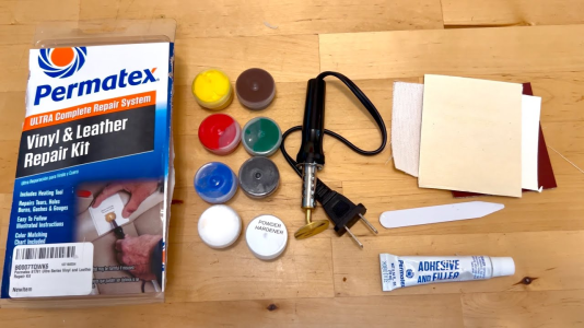
Bummer! Sorry to send you off on a wild goose chase. I haven't done it in some time. It worked when I did it last, although I turned up the density all the way on my printer to get as much printing medium on the printed page as I could. I taped the copy to the workpiece so it wouldn't move when I ran my heating iron over it. I used a little heating iron that came with a Permatex vinyl upholstery repair kit I bought to fix a tear in a car seat ages ago. The Permatex kits are ten or fifteen bucks (or were... maybe $25 these days) and are a stock item at any auto parts store. As pictured below, the heating iron is designed for localized heating at medium heat that won't burn car seat vinyl fabric. It has a flat brass disk about the size of a quarter that heats up. I can't remember the repair kit being all that effective, but the little heating iron that came with it was a keeper. I've used it on occasion for similar tasks ever since. :) When I get past dealing with my upcoming kidney stone surgery, I'll try to get to doing a "how to" on it. Good idea!


1785881655579.png
 
Does an inkjet printer use this same tech? Does a laser Printer?
This is getting a little bit outside of my wheelhouse, but based upon what I've looked up, and absent actual testing, I would think that an inkjet printer should also work because it uses the same "fused plastic powder" process for making a print. In short, if your printer turns out paper prints that are warm to the touch, it should work for the secondary transferring of images.

*************************************************************************************************************************************
Here's what AI has to say about how the electrostatic copying process works:

"Electrostatic printers use electrical charges to transfer toner or ink onto a surface... . A photoconductive drum or belt... is initially given a uniform electrostatic charge. A laser or LED light selectively exposes areas of the drum according to the digital image or text. The light neutralizes the charge in the illuminated areas, leaving the unexposed regions charged. This forms a latent electrostatic image, which is invisible but contains the electrical pattern needed to attract toner particles. Toner particles ... are applied to the drum. These particles are attracted to the charged areas, making the latent image visible as a layer of toner. Electrostatic principles are also used in continuous inkjet systems, where individual ink droplets are charged and steered by deflection plates to form precise images. In color printing, this process is repeated for each toner color ... to build a full-color image. The charged toner is then transferred from the drum to the paper or other substrate. Finally, the toner is permanently bonded to the paper through a fusing process involving heat and pressure. Heat melts the toner particles, embedding them into the fibers of the paper, while pressure ensures a smooth, durable finish."

******************************************************************************************************************

The process I described above is simply the further step of transferring the fused printing medium, melted plastic powder on paper, to a further smooth wooden surface (or other substrate) by adding heat and pressure to re-melt the printed fused powder so it transfers the image (in reverse) to the adjacent surface.

Most printers will have an image intensity adjustment feature which will regulate how light or dark the printed image will be. In this application, it is advisable to experiment to determine whether on the particular machine used a darker image, which should cause the machine to deposit more printing medium (powder) will produce the best results based on the theory that the more printing medium is on the original, the easier it will be to get a good transfer to the secondary transfer surface.


The Permatex vinyl repair kit works on the same principle as the electrostatic printer to melt plastic medium to "putty" tears in vinyl upholstery fabric, plastic auto dashboards, and the like. The heating disk on the provided plug-in iron gets hot, but not so hot that it can scorch or burn the material. I would estimate it is equivalent to the heat from a clothing iron on "low" temperature setting. (Your mileage may vary, so experimentation is advised.) The "original" from the machine is placed, printed side down on top of the surface to which it is to be transferred. The "original" must be secured with its edge taped or pined so it does not move when the back unprinted side is gently burnished with the heat source. Otherwise, the re-liquified printing medium will smear and make a mess of it. The "original" must be left in place until it cools sufficiently for the printing medium to return to its solid state, as it does before the "original" comes out of its printer. The original can then be removed from the target surface and a reverse image of the "original" should be transferred to the target surface.

This technique can be used for transferring parts drawings to the wood pieces what are to be cut out from the patterns, but again, it is important to remember that the transferred image from an "original" will be reversed on the target surfaces. Therefore, the part will end up being as if the cutting was done from the reverse side of the part and the part must be turned over to orient it as the pattern was originally pictured on the original pattern image.

Of course, if one has software which permits a digital image to be inverted before printing to yield a printed reverse image, this feature will eliminate the inverse or "mirror image" issues discussed in the paragraph above.

*********************************************************************************************************************
AI generated instructions for reversing image to create "mirror" images:

Methods to Invert or Flip an Image for Creating Transfers or "Mirrored" Images​

Using Microsoft Paint (Windows)​

  • Open your image in Paint.
  • Select the entire image or canvas.
  • Go to the Home tab, click Rotate, and choose Flip Horizontal for a left-right mirror or Flip Vertical for top-bottom inversion.
  • Optionally, use Invert Colors under the Colors menu to create a negative effect, which flips light and dark areas for artistic purposes.
  • Save the flipped image and print directly.
Using Windows Photos
  • Open the image in Photos.
  • Click Edit > Flip to mirror the image horizontally. the Print dialog to select your printer and print the mirrored image.

  • Using macOS Preview

  • Open the image in Preview.
  • Click Tools in the menu bar and select Flip Horizontal.
  • Save the flipped image and print

  • Using Adobe Photoshop

  • Open the image in Photoshop.
  • Navigate to Image > Image Rotation > Flip Canvas Horizontal.
  • For layered images, you can also use Edit > Transform > Flip Horizontal.
  • Save a new copy to avoid overwriting the original and print

  • Using Online Tools

  • Platforms like Canva, Photopea, and Pixlr allow you to flip images online for free.
  • Ensure the image resolution is high (300 dpi or more) for quality printing

Tips for Printing Flipped Images​

  • Check the purpose: Only flip images when necessary, such as for iron-on transfers or mirrored designs.
  • Preview before printing: Use your printer’s preview function to confirm orientation.
  • Mind text: Text must be mirrored to appear correctly on the final product.
  • High resolution: Use high-quality images to avoid pixelation after flipping.

  • By following these steps, you can successfully invert or mirror your image to achieve the desired print outcome.
**********************************************************************************************************************
This technique can also be used for other modeling applications. It is especially helpful for transferring intricate details for laying out carvings. It can create highly detailed scale nameboards and transom "name and homeport" lettering, painted scrollwork on trailboards, and any other fine scale lettering on a model, such as signage and even manufacturers' labels on deck equipment and so on. In some instances, it may even work on very fine material for making flags. The process is limited to the extent of the modeler's creativity. While another way of achieving similar results is to use the blank transparent decal transfer sheets made for use in electrostatic printers, if the electrostatic heat transfer process is suitable for the application, it's a good alternative to avoid the often-maddening problem of getting the decal to be truly invisible on the applied surface and the disappointing delayed yellowing, peeling, and/or cracking of the transparent decal material due to the decal medium's poor archival quality.

​

 
Last edited:
Something to which I had never given much thought before is regarding bolts used to go through chocks and scarphs on frame assemblies. I have done a bit of searching but cannot find if the bolts were copper or iron in the mid 18th century, specifically about 1744. Anything I could find on sizes give a range of 1" diameter to 1.5" diameter depending on the size of the futtocks. The size difference is negligible at 1:48 (0.021 to 0.031) Barring contemporary information for a 44 I am going with 1 1/4", (0.026" - 0.67mm) The closest copper wire I can find is 22 gage (0.025) which should look right.

In 1744 were iron or copper bolts used? I plan to use copper wire then either blacken them in situ with liver of sulfur to look more like iron or a vinegar and Miracle Gro fertilizer solution for a green patina but I am not sure which is more appropriate. This is probably somewhat minor stuff in the end, but as they will be in view on the exposed frames in the dead flat I would like to get this right.

Thanks for any input.

Allan
 
I think that practical and economical factors would determine the material used.

Copper is expensive and not all that strong.
Cast iron was less expensive and easily fabricated.
The frames were not supposed to be continuously submerged so aggressive erosive rusting should not have been a problem.
Wood does not spall. If the iron rusts and swells - it compacts and is less likely to let go of the iron.

Thinking like the heavy industry shipyard managers of 18C. England (with no engineering 101 background):
Tool steel for thread cutting was probably expensive.
Square cast iron spikes. A tapered half tip. A flat head.
Drill a round hole thru the frame assembly that was the diameter of the flat to flat dimension of the square cross section of the spike. Grease the hole with hydrophobic gloop. Drive the spike until the head is flush. Place a washer down the protruding tip. Hammer it - roved over or ductiled to a puddle - whichever was less work.

The bends would probably have had this done on the yard floor before pulling them vertical.
I have no guess as to how the filling frame floaters could have been attached to the bend beside them - if they were.
 
Per the book “Ships’ Fastenings by Michael Mc Carthy bolts used to assemble double, “sistered” frame pieces were iron. Of course once ships began to be copper sheathed use of iron underwater became problematic.

Metallurgy 101- the iron used would have been wrought, not cast iron. Wrought iron is an ancient material made by stirring, “puddling” semi melted iron. The result is an amalgamation of iron and slag. It is ductile at room temperature and has quite good corrosion resistance.

Steel is an alloy of iron and carbon. The amount of carbon determines the ductility and ability to harden by heat treatment the alloy. Steel was available since ancient times but in very small quantities as it was very expensive. For example the barrels of muzzle loading rifles were made of iron. Use of steel was restricted to the lock mechanism. The invention of the Bessemer Converter and the Open Hearth method in the second half of the Nineteenth Century reduced the cost of steel to where its use became widespread.

Roger
 
Roger has the best answer above. The primary fastener material for ship's timbers in the eighteenth and nineteenth century (and for quite a while longer) was wrought iron, which is not excessively prone to rusting (unlike the far more expensive to make steel.) (Bronze and monel metal keelbolts fastening lead keels was a later innovation in "yacht quality" construction.) Copper was expensive and relatively soft compared to iron and so not used at all. The iron rods which were to hold against axial tension (parallel to their length) were often secured at one or both ends by hammering over an iron rove placed on the iron rod. The iron rods, called "drifts" were often driven in pairs, or larger multiples, at opposing angles to each other. Two drifts driven close together at, say, 30 degree angles to each other in opposite directions would create a fastening that would hold two timbers together far more securely than one drift driven straight down. For example, floor timbers would be secured with pairs of drifts driven at angles forming a "V" in line athwartships. The protruding tops of these drifts would then be peened over roves. This would create a very much stronger connection between the floor and top of a keel timber than a single drift driven straight down into the keel in axial tension.

For fastening timbers such as futtocks, where the tension on the fastening would be in shear (perpendicular to the joint,) the strength of the fastening would be relative to the diameter of the fastener, so the roves would probably have been omitted. The relatively rough edges of hand-wrought iron bar stock would be driven into tightly fitting holes, so where the fastening would be in shear tension, the fastening's pulling out was highly unlikely, if not categorically impossible.

Driving drifts was somewhat of a highly skilled shipwright's specialty because the hole that was bored for the drift had to be tight enough to hold the drift tightly, but not so tight that it could not be driven to the desired depth. It was not entirely uncommon to have a auger bit "freeze" in a deep bore hole and have to be "abandoned" by cutting off shank, filling the open spaces of the bore with molten tar, and plugged and another bore made. Because a drift properly driven into a timber was virtually impossible to withdraw, there was no need to thread the rod to place a nut on the end of it (which would only make sense if later disassembly of the joined parts was contemplated.)

While wooden ships were commonly "recycled" for their spars and rigging, etc., after stripping by the breakers of all accessible recyclable parts, they were usually "burned for their fastenings" to reclaim the heavy iron drifts used to fasten the framing timbers that were impossible to disassemble.

I learned these bits of trivia from an old master shipwright who took pity upon me while was trying to salvage a lead keel from the keel an old wooden boat in the knacker's yard when I was just a young kid.

 
Last edited:
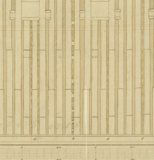
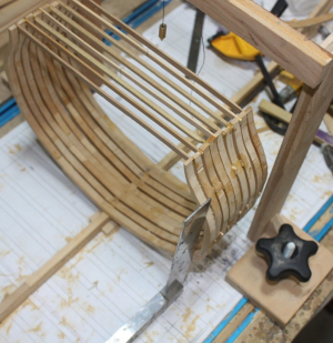
Raising frames.... The moulded dimensions of the frames are about 0.5-1mm oversized so there is a lot of room for fairing. Frames further forward and aft will have more "meat" to be able to fair them to the final beveled shape. In my experience I have found using a plumb bob and machinist squares for every frame are essential, including preventing cumulative error. Temporary cross spalls make sure the breadth is correct and temporary spacers for the proper spacing along the length of the frames can be seen. The cross pieces will be removed later and the spacers will be redone and glued in place based on drawings such as the one below. In the case of Fowey the archeologists and I came to the conclusion that the spacing midships had three frames butted together at the floors and first futtocks, then two frames with a space, then two butted, &c.

Regarding the spacers, I cannot find anything describing these before the last half of the 18th century so far. If anyone has any information I would appreciate hearing about it.

The more I study the look and strength of the final hull I will likely including the garboard and two or three strakes adjacent the entire length as well as several at the sheer rail. This will still leave the framing in the deadflat well exposed as was requested.

Allan

Example of spacers between frames on another ship circa 1775
1787226111748.png
1787226129215.png
 
Last edited:
Thank you very much. :) I actually hate this part of the build, before the fairing is done as it looks so rough, but such is our lot in this hobby.
Ah, the challenge of patience...

As I lack that trait in its fullest form - I found that doing some preliminary fairing of the inside of the hull was helpful as I went along. As you know, access becomes an issue later.
 
As I lack that trait in its fullest form - I found that doing some preliminary fairing of the inside of the hull was helpful as I went along. As you know, access becomes an issue later.
Thank you Paul,
I agree completely. For the dead flat it is not a problem, but for the frames fore and aft of the dead flat I do some beveling before raising the frame. When drawing the frames I did show the amount of bevel I need to do so it will take care of most of the work off the ship. You are right, it is MUCH easier to do off the ship, just need to be careful not to over sand and then have to make a whole new frames....... and yes, regrettably, I have had it happen more than once on previous projects.
 
Back
Top