• Ships of Scale has incorportated an extra level of security when you log In. Please follow on-screen prompts to acknowledge that you are not a robot via a "Check Box" or a "Pictorial Check Box Puzzle". This is needed due to higher level of AI Activity Security.
  • SUBSCRIBE TO SHIPS IN SCALE TODAY!

    The beloved Ships in Scale Magazine is back and charting a new course for 2026!
    Discover new skills, new techniques, and new inspirations in every issue.

    NOTE THAT OUR NEXT ISSUE WILL BE July/August 2026
  • Win a Free Custom Engraved Brass Coin!!!
    As a way to introduce our brass coins to the community, we will raffle off a free coin during the month of August. Follow link ABOVE for instructions for entering.

Received my Proportional Divider, but How-to?

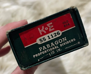
In summary, what you want to look for on eBay is a Keuffel and Esser 10" "Paragon" proportional divider with "110" decimal scaling.
Thanks Bob. I also love drafting tools and want to own the best ones. I shortly used them in my Engineering career when switched to CAD in about 1996. Just purchased a divider you recommend on eBay US. Looks like as new condition in pristine original casing. Even the carton box is available.

1788306439012.png

1788306489905.png
 
The info can be found ,I think) with this url: (https://shipsofscale.com/sosforums/threads/ship-line-development.15656/page-2) . An artical iin Wikipedia explors the subject: Transversal (instrument making)
I first found the method in Chapelle's Yacht Designing and Planning. I'm finding that another member with better knowledge of the subject has written about it here in SOS. Also, find some references from google AI. I'd go to the office and look up Chapelle's illustration and explanation. but I have to go fix breakfast now.

To answer Allegheny's question.​

 
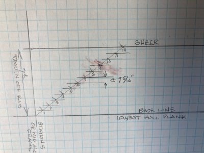
Wouldn't you know, my desk top is evidently on holiday tonight. I made a sketch showing how a draftsman would divide an odd measurment into a disired number of transversal joists , stair treads or risers, or planks on a particular section or rib of a boat. The angled line is drawn using a ruler with any regular divisions equaling the number of planks. The desired plank widths are measured vertically from the bottom line to the tic. Also is shown the graphic representation of an old style "scale". I'm posting pictures from my phone of what I spoke of. I hope they answer your basic question.
Now, if you have the proportional dividers, it doesnt matter if the measurements you take are absolute, it is all relative to the drawings you're working from. If the parchment, reprodution or velumn you're working from, the accuracy of the scale you're using is a set of ratios, so as long as there is consistancy, you're ok. This would matter to a builder because he might be workng from loftings drawn on a floor, a wall, or heaven forfend. strings and marks in the dirt. As long as you're working with drawings and divisions, try getting a 10 point dividers. Also, I don't believ it's necessary to mark every frame. Set up the ends and the middle and use a temporary batten to see where the plank should lay and where it would be good to alter the width.
When it comes to laying out your planks, lining off, remember that the boat and the build work the best with evenly sized planks down from the sheer to the water line, for both looks and function. When you get much below that in most designs, you have to start patterning or spiling your planks, and setting up widths for wild edge set and nibbing the ends where they run into the stem or the tuck. With a model, this is the area where filler and or copper plate can hide everything. I suppose with admiralty models, shortcuts are no good, but for your picture window or credenza in smaller scales, the difference is lost.

rIMG_2901.JPG

IMG_2902.JPG
 
Last edited:
Wouldn't you know, my desk top is evidently on holiday tonight. I made a sketch showing how a draftsman would divide an odd measurment into a disired number of transversal joists , stair treads or risers, or planks on a particular section or rib of a boat. The angled line is drawn using a ruler with any regular divisions equaling the number of planks. The desired plank widths are measured vertically from the bottom line to the tic. Also is shown the graphic representation of an old style "scale". I'm posting pictures from my phone of what I spoke of. I hope they answer your basic question.
Now, if you have the proportional dividers, it doesnt matter if the measurements you take are absolute, it is all relative to the drawings you're working from. If the parchment, reprodution or velumn you're working from, the accuracy of the scale you're using is a set of ratios, so as long as there is consistancy, you're ok. This would matter to a builder because he might be workng from loftings drawn on a floor, a wall, or heaven forfend. strings and marks in the dirt. As long as you're working with drawings and divisions, try getting a 10 point dividers. Also, I don't believ it's necessary to mark every frame. Set up the ends and the middle and use a temporary batten to see where the plank should lay and where it would be good to alter the width.
When it comes to laying out your planks, lining off, remember that the boat and the build work the best with evenly sized planks down from the sheer to the water line, for both looks and function. When you get much below that in most designs, you have to start patterning or spiling your planks, and setting up widths for wild edge set and nibbing the ends where they run into the stem or the tuck. With a model, this is the area where filler and or copper plate can hide everything. I suppose with admiralty models, shortcuts are no good, but for your picture window or credenza in smaller scales, the difference is lost.

rView attachment 631554

View attachment 631555

Dear @18Lyman ,

Thank you very much for the sketch of the method you were trying to describe.
The method's description along with the sketch helped me immensely.

Thanks!
 
The most useful thing that I use my proportional dividers for is finding the width that planks have to be tapered down to. You can do this without measuring and calculating by using the following method. Lay a strip of paper on the bulkhead that is to have the planks laid across. Mark two pencil lines accurately with a very sharp pencil, one at the keel end of the strip and another at the opposite end. You now have the total width of all the planks. If you want 9 planks in that space, set your dividers to 9 ON THE LINE SCALE. Then open them so that one LONG pointer is at one of the pencil marks and the other long pointer is at the other pencil mark. The distance between the SHORT pointers is the width that each of the 9 planks must be tapered to. You can, of course, use any number depending on how many planks you must fit onto the bulkhead. Basically, the numbers on the line scale divide a line into that many pieces. I would urge you to seek out an old pair of metal, engineering/draftsman’s dividers. They are more expensive than the plastic variety but they are absolutely beautiful and far more accurate for our hobby in my experience. I think that the plastic ones are aimed more at artists who use them to measure proportions by holding tips to pass the permit test them out at arms length rather than sticking the pointers into solid materials.
How to do to seek out an old pair of metal?
 
Hallo,1791264455629.png

Sehr interessanter Artikel. Ich habe evtl. eine sehr banale Frage zu „alten“ Maßstabsangaben / Darstellung und hoffe hier auf euer fachliches Wissen.
Kann mir bitte jemand das „Lesen“ und die „praktische Anwendung „der alten Maßstabsdarstellung erklären und aufzeigen? Ich wäre darüber sehr dankbar.
 
Hallo,View attachment 641704

Sehr interessanter Artikel. Ich habe evtl. eine sehr banale Frage zu „alten“ Maßstabsangaben / Darstellung und hoffe hier auf euer fachliches Wissen.
Kann mir bitte jemand das „Lesen“ und die „praktische Anwendung „der alten Maßstabsdarstellung erklären und aufzeigen? Ich wäre darüber sehr dankbar.
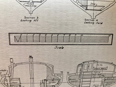
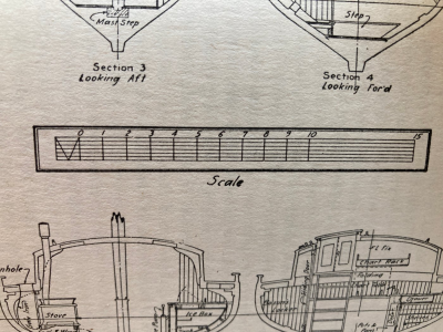
The scale shows the lengths in feet at the scale of the plans. If the plans' scale is e.g. 1:48, the distance from 0 to 1 (1 foot =12" in reality) would be 1/4" (inch).

Die Skala zeigt die Länge in Fuß im Planmaßstab. Wenn die Pläne im Maßstab 1:48 gezeichnet sind, ist die Länge von 0 bis 1 (1 Fuß) auf der Skala 1/4" (Zoll).
 
Die Skala zeigt die Längen in Fuß im Maßstab der Pläne an. Beträgt der Maßstab der Pläne beispielsweise 1:48, beträgt also die Entfernung von 0 zu 1 (1 Fuß = 12 Zoll in der Realität) 1/4 Zoll.

Die Skala zeigt die Länge in Fuß im Planmaßstab. Wenn die Pläne im Maßstab 1:48 gezeichnet sind, ist die Länge von 0 bis 1 (1 Fuß) auf der Skala 1/4" (Zoll).
Danke Dir für die Erklärung. Ist deine Ausführung bezogen auf die obige Maßstabsanfabe / Maßstabsdarstellung ?
 
Danke Dir für die Erklärung. Ist deine Ausführung bezogen auf die obige Maßstabsanfabe / Maßstabsdarstellung ?
Das ist ganz allgemein; eine solche Skala findet sich meist auf Plänen. Du brauchst halt den Maßstab (1:48, 1:72, 1:87). Die auf dem Plan gemessene Länge, z.B. 6,35mm bei 1:48 entspricht dann 1 Fuß im Original.

It's not specific, such a scale is shown on most plans. You need the scale in which the plans are drawn. If the scale is 1:48 (3/16") and you measure 6.35mm (1/4") for 1 division of the scale, this means 1 foot in the original ship (1:1).
 
It is what one might call a “universal” scale. It represents feet and inches for what’s on the drawing. Using dividers one can easily pick unknown dimensions off and measure on the scale. If the drawing for some reason shrinks or is reproduced to a different size the scale can still be used as it changes size as well.

Roger
 
Back
Top