


• Ships of Scale has incorportated an extra level of security when you log In. Please follow on-screen prompts to acknowledge that you are not a robot via a "Check Box" or a "Pictorial Check Box Puzzle". This is needed due to higher level of AI Activity Security.
  • SUBSCRIBE TO SHIPS IN SCALE TODAY!

    The beloved Ships in Scale Magazine is back and charting a new course for 2026!
    Discover new skills, new techniques, and new inspirations in every issue.

    NOTE THAT OUR NEXT ISSUE WILL BE July/August 2026
  • Win a Free Custom Engraved Brass Coin!!!
    As a way to introduce our brass coins to the community, we will raffle off a free coin during the month of August. Follow link ABOVE for instructions for entering.

HANNAH

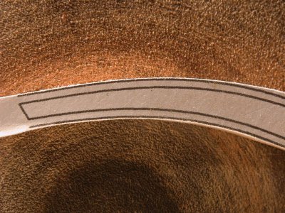
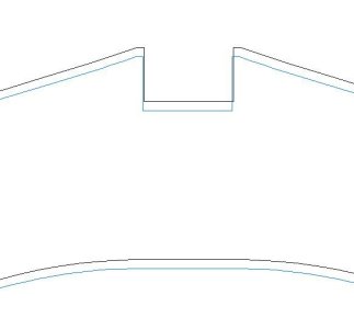
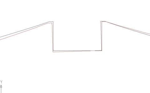
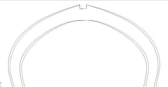
Here are two pictures associated with the Rattlesnake keel / plan / assembly jig. In the semi kit, the keel parts are laser cut as is the assembly jig. So here it is most important that the keel notches matches the jig than the plans. There seems to be creep when placing the laser cutting over the plans:

Keel against Plan.jpg

But there is no visible creep when keel is compared with the jig:
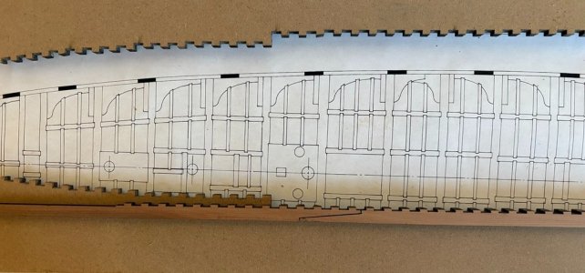
Keel against Building Jig.jpg

I did not check to see if the plans for the keel and the jig are in alignment. However, the difference between plans and laser cutting could be a function of the plans changing shape with moisture content. What's most important is the jig and the keel are consistent. If one was scratch building both the jig and keel, again it would be a matter of consistency as Dave notes above.

Notice that care must be taken in assembling the two sections of the keel at the scarf joint. This must be done to preserve the width of the notch bisected by the joint. If this is not done, that notch will be the incorrect size, but more importantly it will no longer be possible to align all of the notches in the keel with the respective notches on the jig. If you align the fore part of the keel, all the aft slots will be out of alignment and vice versa. If you align at the notch over the scarf joint, the rest of the notches - fore and aft - will not align.

So here I see a tradeoff of having the laser cut part and scratch building the keel. If the keel is scratch built, the scarf joint can be done very nicely to join two pieces of stock a bit longer in total than the finished keel. The notches can then be created with no chance of the joint causing spacing problems. Again the notches would need to be made consistent with spacing of the assembly jig. The keel would then be trimmed to the final dimension.
 
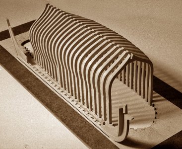
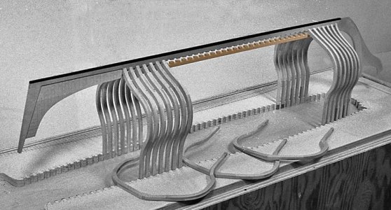
when i comes to the actual building of the hull there are two approaches the Hahn way which is to cut and finish each frame including the bevels then set that finished frame into the hull.

xconfed78.jpgxconfed77.jpgxconfed70.jpg

The second method is to cut the frames with extra wood beyond the frame shape then assemble the hull and sand the hull as one unit.

You still have to be careful to maintain a consistent shape of the frame you cannot be sloppy about cutting out the frames


ps1.jpg

Try and keep the same extra wood along the frame line.

ps3.jpg
 
i would not call it a flaw or error in the Hahn system because it works so i will say the Hahn way and everyone else's way.

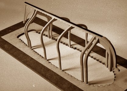
First setup is placing the first and last frames in the jig square and level.


2hannah21.jpg

the issue here is you have to remove the keel to install the rest of the frames which removes you reference point where the frame fits the keel notch.

2hannah23.jpg

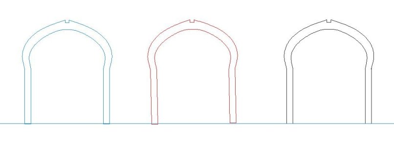
In order to get every frame perfectly in line depends solely on the accuracy in which you cut the frame. Looking at 3 frames sitting in the jig if you the slightest off on the length of the frame legs the hull will be off.

lineup1.JPG


taking the blue frame, If you short on the legs the notch will be at a different level

lineup2.JPG

the red frame if one leg is shorter or longer the frame will tilt in the jig

lineup3.JPG

that very small tilt has a big effect on the placement of the frame in the hull. Zooming out you can see what happens.

lineup4.JPG

By cutting the frames over size will allow for micro adjustments when it comes to sanding the hull. but if you finish the frames before you build the hull there is zero tolerance in building.
 
There are a number of work arounds to the original Hahn system such as this one why not after setting up the first frames at each end and one in the center glue the keelson in place. Notches in the keelson match the notches in the keel so now you have a reference point at the keel. Why not cut the frame pieces over size then assemble the frames giving yourself more room to finish the frames and save on the wood from the blank method? All in all the builders kept to themselves and solved problems.

xconfed79.jpg

i met Harold Hahn back in the 1970s and we remained friends till the end. during that time The Lumberyard for model shipwrights sold a lot of timbering set of his models but in all that time very few ever showed up in build logs. Some reasons are the builders were in a separate group either they graduated from kit building or were scratch builders from the start so they had no need to create a build long on a forum that focused on kit building another reason was a lack of detailed instructions Harold expected you to know what you were doing before you started the build. In the early days Harold and the Nautical Research guild were tight, and all his articles appeared in the journal. Then the nit picking and the final falling out and Harold and the NRG went their separate ways. Building of the models continued but the builders remained silent and did not want to be involved with the controversy around the Hahn system or because he put little figures on the models which at the time was considered a sin against the traditional admiralty style. Other reasons were and still are the system is workable but accurate craftsmanship is required and the carvings were a detail few builders could accomplish.

CAD drafting, laser cutting and 3D printing evolved the hobby and the Hahn system has been reworked into the Hahn system 2.0
 
Last edited:
What I find interesting, is that "jig" systems are showing up in a lot of kits these days, and they were never part of the traditional POB kits over the years
Of course their usefulness with a handful of frames would be minimal. `
Still, how often do we hear about the struggle with squaring up the bulkheads/frames of traditional kits?

It seems to me that Hahn was the pioneer with this type of system.

Your work is a great example of usefulness of this type of build.
 
It seems to me that Hahn was the pioneer with this type of system.

that is true it was Harold Hahn who introduced building hulls in a jig and the kit industry ran with the idea and came up with variations
Of course their usefulness with a handful of frames would be minimal. `
Still, how often do we hear about the struggle with squaring up the bulkheads/frames of traditional kits?


the Hahn system was for POF, the kits using POB is an entirely different type of build
 
It doesn't mean they can't benefit from a jig that aids squaring. Which in the end, is what the Hahn system does.

If you take a look at the build log for NRG Rigging project, you will see my jig that squares up the seven frames/ bulkheads.

View attachment 645240

i get what you are saying here the Hahn jig system is not part of the hull structure, you're building a hull IN a jig. What you are showing is the bulkhead structure and the piece to line up the bulkheads is part of the structure. Which serves the purpose of locking in the bulkheads square to the center profile. I have seen this 30 years ago and it works for a POB hull.
 
Last edited:
Back
Top