Thanks, Daniel. I hope so, but the new shop will be much smaller than I wanted. That’s a story unto itself…From the looks of the framework, you're going to have one beautiful new home Namabiiru.
-

Win a Free Custom Engraved Brass Coin!!!
As a way to introduce our brass coins to the community, we will raffle off a free coin during the month of August. Follow link ABOVE for instructions for entering.
You are using an out of date browser. It may not display this or other websites correctly.
You should upgrade or use an alternative browser.
You should upgrade or use an alternative browser.
Wow! That is a REALLY nice base! Now the pressure is on to have the ship model sitting on it be worthy...
It took 15 months to build the house I live in right now - that's 8 days in Japanese time .
.
It took 15 months to build the house I live in right now - that's 8 days in Japanese time
Thank you, Paul. The base, like the ship that will sit on it, has plenty of blemishes which I hope few other than myself will notice.Wow! That is a REALLY nice base! Now the pressure is on to have the ship model sitting on it be worthy...
It took 15 months to build the house I live in right now - that's 8 days in Japanese time.
- Joined
- Jun 17, 2021
- Messages
- 3,100
- Points
- 588

Having restored a lot of 18th and 19th c. American furniture where figured maple was very popular and iconic, your choice of figured maple is perfect for an18thc. American Revolutionary War Privateer! Even the bracket feet are period correct!In addition to assorted bits and bobs of progress, I made good progress on the base.
View attachment 544554
The pedestals and feet aren’t attached yet. I’ll do that after I’ve drilled holes for screws and a switch and routed channels for wiring underneath.
The base itself is made from a slab of what I think is Birdseye Maple my Dad let me scrounge from his basement many years ago.
Thank you, Peter that’s very encouraging. In truth, it was a combination of what I had on hand and TLAR design.Having restored a lot of 18th and 19th c. American furniture where figured maple was very popular and iconic, your choice of figured maple is perfect for an18thc. American Revolutionary War Privateer! Even the bracket feet are period correct!
- Joined
- Nov 27, 2024
- Messages
- 72
- Points
- 88

The ship base looks very nice, I feel like it could work as is. I didn't realize you were planning to rig up some lighting for it, though. I guess I need to catch up.
Thank you. The base itself won’t be lit, but the wiring for the ship’s interior will be run through the base.The ship base looks very nice, I feel like it could work as is. I didn't realize you were planning to rig up some lighting for it, though. I guess I need to catch up.
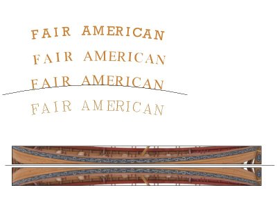
For the next project, if you have any kind of CAD program you they usually have hundreds of fonts from which to choose. You can size every thing perfectly and print on black or any color paper then apply to the counter. The below are a few examples. The scroll work is another thing that can be done with the computer printer. I downloaded a photo from RMG of a ship's boat and cropped it. I then inserted it into the drawing and sized it for the boat model. It was then copied as a mirror image so I had port and starboard then printed. I next trimmed the scroll work and glued to the model.
Allan
Allan

I love your choice of font.View attachment 545977
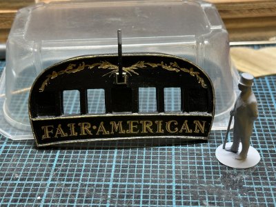
Mr Basswood inspects the newly completed nameboard. The font is not a perfect match and a little big, but it was the closest I could find.
At last, the transom is nearly ready to be installed.
Thank you, Allan. I’ve used that technique on other models. I did mess around with Powerpoint to get something pretty close when I thought that a Cricut stencil might work, but I decided printing gold on paper was not going to look convincing. Not sure this does either, but at least it’s gold.For the next project, if you have any kind of CAD program you they usually have hundreds of fonts from which to choose. You can size every thing perfectly and print on black or any color paper then apply to the counter. The below are a few examples. The scroll work is another thing that can be done with the computer printer. I downloaded a photo from RMG of a ship's boat and cropped it. I then inserted it into the drawing and sized it for the boat model. It was then copied as a mirror image so I had port and starboard then printed. I next trimmed the scroll work and glued to the model.
Allan
View attachment 545978
Last edited:
Thank you, Daniel. It’s a bit more baroque than what is shown in the plans, but does seem to go with the the rest of the gold embellishments.I love your choice of font.
Thank you, Günther!Hey Namabiiru,
Really beautifully drawn. It looks great.
I’m sure many readers were observant enough to notice in my last update that there were no window frames in my “complete” transom, but were equally polite not to point out my glaring omission.
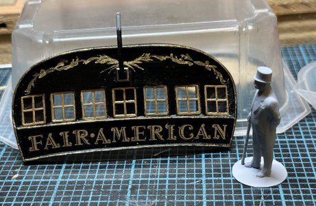
Mr Basswood, however, was not so polite. I can only surmise from the language he used that he was at one time a sailor prior to owning his own shipyard. He said he’s going to dock my pay for this.
Anyway, lucky to have caught it when I did because it turned out, contrary to my normal standard of precision, that the perfectly fitted window frames didn’t actually leave enough clearance for the layers of paint and varnish. Some surgery was required to get the frames to go in.
- Joined
- Jun 28, 2020
- Messages
- 457
- Points
- 323

Namabiir,I’m sure many readers were observant enough to notice in my last update that there were no window frames in my “complete” transom, but were equally polite not to point out my glaring omission.
View attachment 546116
Mr Basswood, however, was not so polite. I can only surmise from the language he used that he was at one time a sailor prior to owning his own shipyard. He said he’s going to dock my pay for this.
Anyway, lucky to have caught it when I did because it turned out, contrary to my normal standard of precision, that the perfectly fitted window frames didn’t actually leave enough clearance for the layers of paint and varnish. Some surgery was required to get the frames to go in.
This looks amazing!!
It's the best!
No,no, my friend. It is very humble compared to your Silent Mary. I don’t have half of your patience and skill. But I thank you for your generous words.Namabiir,
This looks amazing!!
It's the best!
- Joined
- Jun 17, 2021
- Messages
- 3,100
- Points
- 588

Super. And I love the font! 

Thank you, PeterSuper. And I love the font!

In order to wire the lighting for the ship before planking the hull, but still leaving the whole thing freely accessible as the rest of the build progresses, I am going to insert electrical contacts into the keel at the points where it rests in the pedestals. The pedestals themselves have leads soldered to the bases
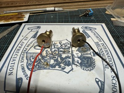
One will connect to the positive side of the power supply, the other the negative side. The resistor and LEDs will be in series so wiring will be simple. I drilled holes for the leads next to the holes for the mounting screws.
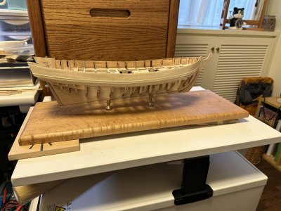
With everything set in place, this is how it looks. No sign of wiring and the ship doesn’t need to stay permanently attached to the base.
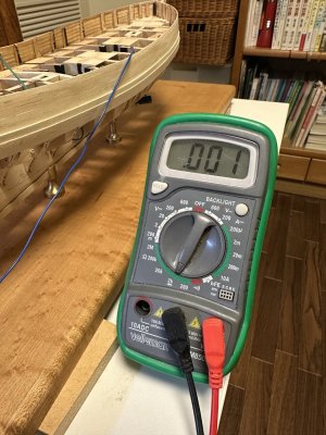
With the contacts installed and the ship resting in the pedestals, resistance across the whole setup is effectively nil. I’ll call it a win.
Just waiting for some resistors to show up in the mail so I can test the lighting properly.
Last edited:


