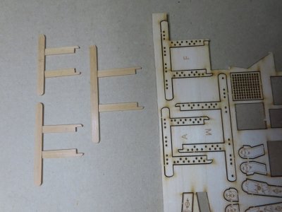
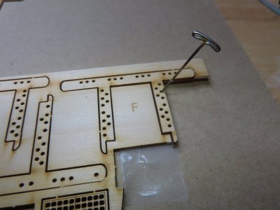
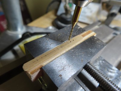
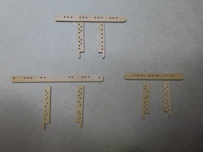
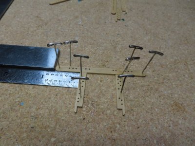
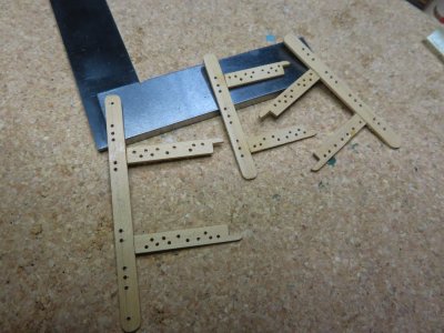
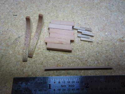
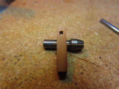
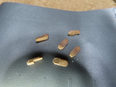
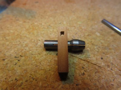
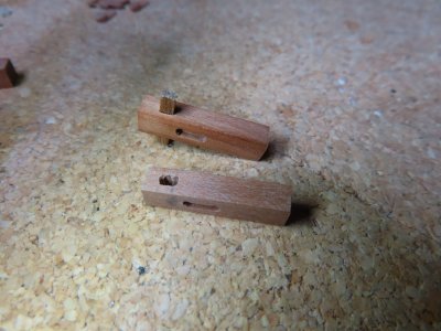
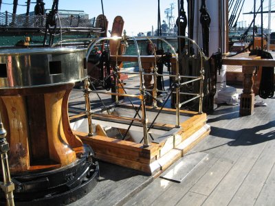
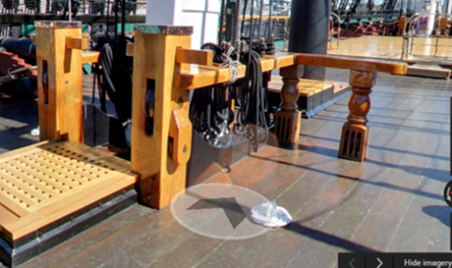
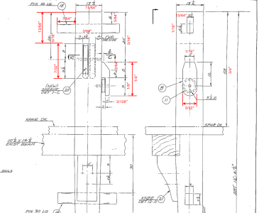
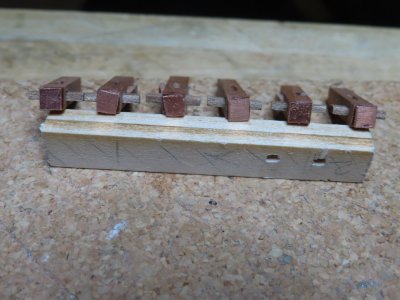
The last component required for the riding bitt posts were the “copper caps” located on the top the post as indicated on the MS plan. The US Navy plans did not show the copper top, but the photographs do. Surprising, the one image I don’t seem to have was a clean clear photo of the top of riding bitt post’s copper cap. I just assumed the top was completely covered in copper. However, Mustafa used a thin copper band going around the stanchion’s top edge leaving the top bare wood. Ken Forman (xKen) used fitted 0.020 copper squares. So, I decided to go to the source and see what the photos showed. Easier said than done. Every one of the photos I had and any I could subsequently find by Googling, were shot level to the top of the post. None showed a view from angle higher than the post height, that is looking down onto the top of the post. When the post tops were not protected with canvas covers, all that could be seen was the copper along the top edge of the post, hence Mustafa’s approach.
View attachment 621156
View attachment 621158
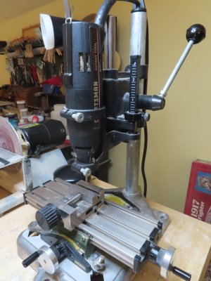
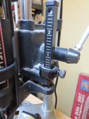
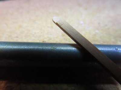
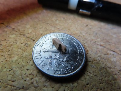
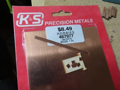
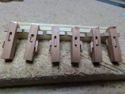
The MS plans used the term “copper cap” not “band” or some other such similar term. Therefore, I followed xKen’s path. I didn’t have a 0.020” copper sheet he used, but I did have a 0.025” copper sheet. I dare you tell the difference at a glance! Using my Byrne’s saw, I cut a 5/32” strip off the sheet and then cut six 5/32” squares from the strip.
View attachment 621159
View attachment 621160
View attachment 621161
View attachment 621162
Now that I had all the pieces fabricated, realized I had better add those objects first that might be difficult to install after I install the fife rail, like eyebolts and ammo scuttles.