• SUBSCRIBE TO SHIPS IN SCALE TODAY!

    The beloved Ships in Scale Magazine is back and charting a new course for 2026!
    Discover new skills, new techniques, and new inspirations in every issue.

    NOTE THAT OUR NEXT ISSUE WILL BE July/August 2026
  • Win a Free Custom Engraved Brass Coin!!!
    As a way to introduce our brass coins to the community, we will raffle off a free coin during the month of August. Follow link ABOVE for instructions for entering.

USS Constitution - Model Shipway’s 5/32” = 1 ft. (1:76.8) Kit No.: MS2040

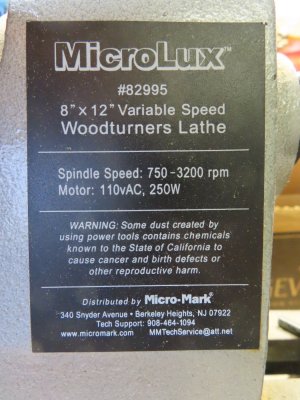
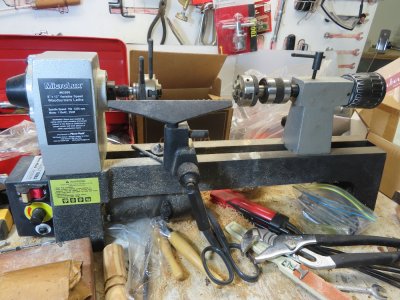
I have a small (not micro) wood lathe that I bought about 20 years ago from Micro-Mark, but it is designed for full size work, It is beefy and powerful. It could twist snap small stock wood with ease if not careful. I might have attempted the stanchions if I had one accessory: a four fingered chuck. Most of my stock wood is square cross section. I have attempted to buy one from Micro-Mark in the past, but they did not offer one that could fit my lathe and I could not find any elsewhere. Now it appears they only sell Sherline products.

Jon

IMG_3097.JPG

IMG_3099.JPG
 
Last edited:
That's quite the interesting setup - three jaw cucks on both sides of the lathe? I suggest you invest in a four jaw (self centering) chuck for the drive side of the lathe and a live center for the other end. With those two changes, you should have no problem turning wood. Had you had nothing but the four-jaw chuck, you could have made quick work of the center bolsters, even if your only cutting tool was a small file.

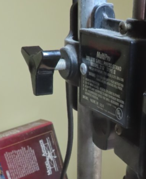
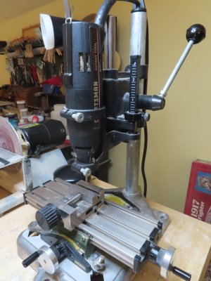
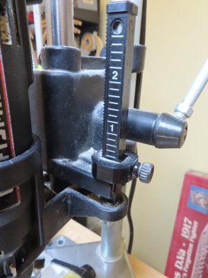
As I said at the other site, very impressive work considering the tools you're handicapped(?) with. But I'll ask again here, how do you lower the cutting tool on that Dremel setup? Hopefully not by loosening this knob and lowering the Dremel manually?

1783028508901.png
 
Peter, as I mentioned earlier, I tried buying a 4-jaw chuck but couldn't find one that fit my lathe. The set up you see in the image above was just to hold the 2nd 3-jaw chuck from rolling around on the bench.

As for the Dremel drill stand, there is a incremental depth stop on the right side. This limits the drill's vertical motion to a set height. The problem with it, is that it can only move the stop by 1/8" jumps as indicated on the scale. Any finer adjustment gets clunky. I either have to adjust the initial height manually by the knob you saw on the left side or adjust the height of what ever I'm drilling. There are no fine adjustment screws. Like I said, a poor man's drill press.

Note, that my Dremel drill stand is the "old" version I bought at least 15 years ago. The newer ones can be rotated 15 degrees at a time and have a variable continuous depth stop. Mine is strictly a vertical or horizontal setup.

IMG_3100.JPG

IMG_3101.JPG
 
I feel your pain. Part of the reason I switched from the Proxxon to the Sherline lathe was exactly because I could not get a self-centering four-jaw chuck for the Proxxon. I went down every rabbit hole suggested by contributors at MSW, and looked at countless YouTube videos explaining how you could get spindle adapters to fit standard available four-jaw chucks to the Proxxon proprietary spindle, but ultimately gave up.

I'm given to understand that the micro mark lathe use standard sized fittings. You should be able to find a 4-jaw chuck and, if need be, a spindle adapter for it.

I asked Gemini, and the A/I agent agrees.

"To mount a 4-jaw self-centering chuck onto your Micro-Mark MicroLux 7x16 mini lathe (Model 82995), you will need a compatible 4-inch plain-back chuck and a spindle adapter plate (backing plate) designed specifically for 7-series mini lathes."

SoS deleted the link to Little Machine Shop for the recommended chuck. Confirm the diameter and number of threads on your spindle, and shop four jaw chucks at Amazon.

I asked Grok the same question, got a similar answer. No adapter should be necessary because a 1 inch by 8TPI spindle nose seems to be the standard. I therefore reiterate, check Amazon for self-centering four jaw chuck's, check the specs to make sure they have one inch by 8 TPI spindle.
 
Thank you Peter for your efforts. Let's hope I find what I need. BTW, I just finished reading your long for the last month. It seems I never got notified of your postings. Beautiful work!!!

Jon
 
Ho accettato la sfida di creare il doppio golfare, ma in realtà non è stato troppo difficile. Utilizzando golfari da 1/16 di pollice, ho piegato l'anello in modo che i due golfari possano stare un accanto all'altro senza sovrapporsi. Questi sono stati inseriti in una molletta da bucato leggermente modificata, usata come morsetto, e saldati insieme con stagno d'argento. Ho provato a usare la pasta saldante d'argento, ma a causa della piccola superficie arrotondata, non riuscivo a farla aderire dove volevo o in modo sufficiente. Quindi, ho ripiegato sull'uso del flussante e di una sottilissima striscia di stagno d'argento da un rotolo. Ha funzionato alla perfezione. Dopo aver limato, rifilato e annito, ho inserito il doppio golfare nel ginocchio verticale.

View attachment 599224

View attachment 599225

View attachment 599226
 
Complimenti!

1- non ti sei arreso di fronte alle difficoltà di costruire in scala il più piccolo dettaglio, risolvendo ogni problema con l'attrezzatura di cui disponevi, senza ricorrere a quelle più sofisticate che pure possono aiutarti
2- hai accettato di nuovo e di nuovo la sfida con te stesso e i tuoi mezzi pur di restare fedele al tuo modello, per rispettare la realtà della tua nave alla data di riferimento
3- con estrema pazienza, provando e riprovando, al massimo della tua capacità, non un punto di meno, scegliendo la soluzione più fedele benché complessa
4- indipendentemente dal risultato della tua fatica è proprio la tua fatica che dà entusiasmo.

Complimenti!
 
Mario54 - Thank you for your praise, I did the best I could with what I had. A lot of my inspiration for ideas and solutions came from reading everybody else's build logs. So without all of you, I could not have accomplished what I have done so far. Thank you all.

Jon
 
Fife Rail

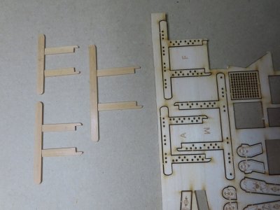
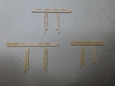
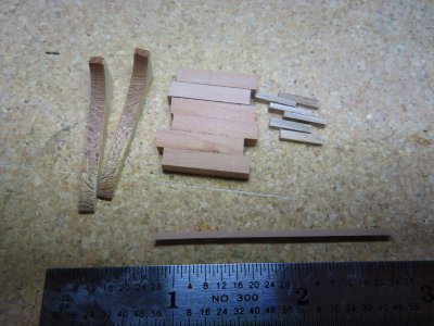
Totally agreeing with Mr. Hunt’s assessment of the kit provided laser cut fife rails as too fragile to work with, I used 3/64” x 3/16” boxwood. This meant sacrificing the kit’s one unit piece fife rail for a three-piece assembly. Now the rails have the advantage of having the wood grain following the length of the rail for added strength. The pieces were cut to length, and then the ends were properly shaped.

IMG_3102.JPG
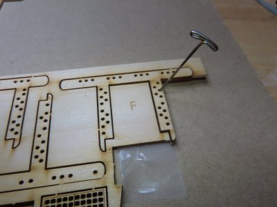
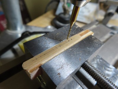
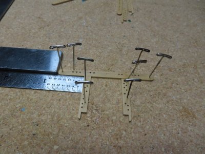
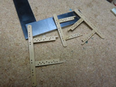
The boxwood pieces were taped to the underside of their corresponding laser cut pieces and belaying pin hole positions were transferred with a pin push through the laser cut holes. The pin marks were overlayed with pencil marks for easier viewing and drilled with a bit that corresponded with the diameter of the kit’s belay pins. I rigged my Dremel “drill press” with a wood strip backing so I could slide the rails under the drill and eventual drill 101 holes (if I did my math right). The pieces were held in place and glued together with clear gel Gorilla Glue. CA may have worked, but I didn’t trust it due to the small gluing surface and porous wood surface.

IMG_3103.JPG

IMG_3104.JPG

IMG_3105.JPG

IMG_3106.JPG

IMG_3107.JPG
 
Last edited:
Riding Bitt Posts

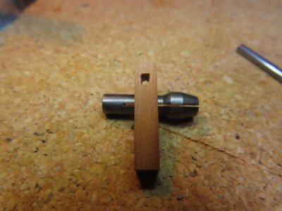
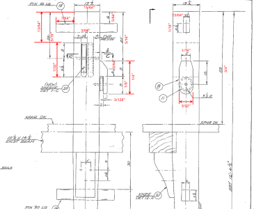
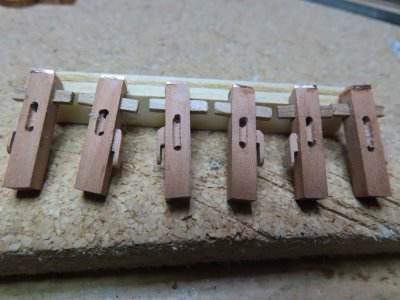
After I gathered my materials for the riding bitts parts, the riding bitt posts were next. They were constructed in a similar manner to the rail stanchions using the same 5/32” square stock pearwood, however, only one sheeve was required. A required external sheeve was attached to one side per post. Due to the scale size of the external 0.026” sheeve thickness and 3/32” diameter, I elected not to attempt to fabricate something no one would likely see.

IMG_3108.JPG

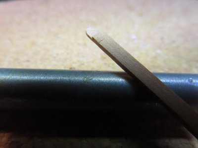
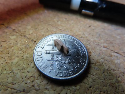
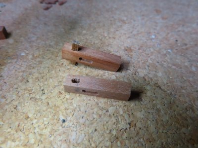
The side sheeve housing was made from 1/16” x 3/32” pearwood stock. A notch was cut at one end of the stock wood using the razor saw cross cutting into the wood 1/8” from the end to a depth of half the thickness of the wood. Then very carefully, a slice was made down the length of the wood stock middle, meeting up with the crosscut, guided by my calibrated eyeball . A few strokes of a fine needle file to smooth things out and then the end was rounded per the US Navy plan.

IMG_3109.JPG

IMG_3110.JPG

IMG_3111.JPG
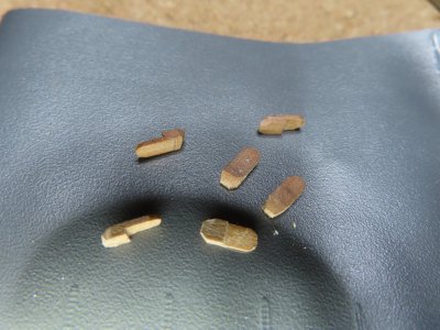
The notched piece was sliced off the stock ¼” from the end and the bevels were filed in to match the US Navy plan.

IMG_3113.JPG

IMG_3114.JPG
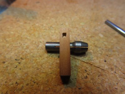
An additional opening had to be made to accommodate the rectangular horizontal bar at the top of the post, 90 degrees from the sheeve. Mr. Hunt, in his practicum, used a round brass rod for ease of construction. The rectangular hole was initially cut on the Dremel “drill press” with two overlapping holes from a 3/64” drill bit to create an opening 5/64” long. These were then trimmed to create the 90-degree corners using micro chisels and needle files.

IMG_3110.JPG

IMG_3117.JPG
 
Last edited:
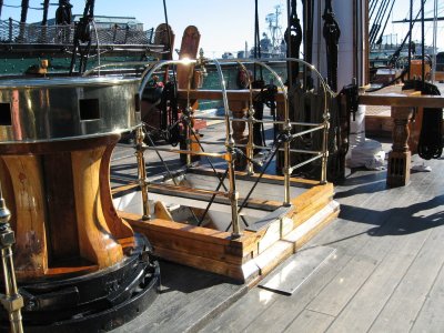
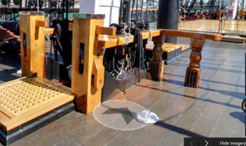
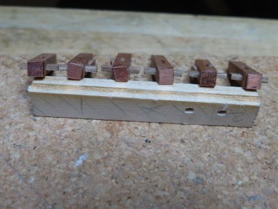
The last component required for the riding bitt posts were the “copper caps” located on the top the post as indicated on the MS plan. The US Navy plans did not show the copper top, but the photographs do. Surprising, the one image I don’t seem to have was a clean clear photo of the top of riding bitt post’s copper cap. I just assumed the top was completely covered in copper. However, Mustafa used a thin copper band going around the stanchion’s top edge leaving the top bare wood. Ken Forman (xKen) used fitted 0.020 copper squares. So, I decided to go to the source and see what the photos showed. Easier said than done. Every one of the photos I had and any I could subsequently find by Googling, were shot level to the top of the post. None showed a view from angle higher than the post height, that is looking down onto the top of the post. When the post tops were not protected with canvas covers, all that could be seen was the copper along the top edge of the post, hence Mustafa’s approach.

2007 01.jpg

Spar Deck Riding Bitt.png

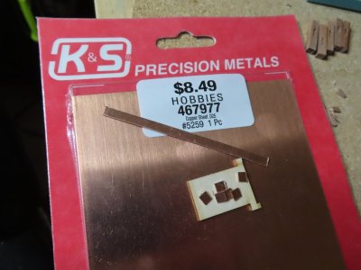
The MS plans used the term “copper cap” not “band” or some other such similar term. Therefore, I followed xKen’s path. I didn’t have a 0.020” copper sheet he used, but I did have a 0.025” copper sheet. I dare you tell the difference at a glance! Using my Byrne’s saw, I cut a 5/32” strip off the sheet and then cut six 5/32” squares from the strip.

US Navy Spar Deck Riding Bitt Plan.png

IMG_3115.JPG

IMG_3123.JPG

IMG_3124.JPG
Now that I had all the pieces fabricated, realized I had better add those objects first that might be difficult to install after I install the fife rail, like eyebolts and ammo scuttles.

 
Back
Top