• SUBSCRIBE TO SHIPS IN SCALE TODAY!

    The beloved Ships in Scale Magazine is back and charting a new course for 2026!
    Discover new skills, new techniques, and new inspirations in every issue.

    NOTE THAT OUR NEXT ISSUE WILL BE July/August 2026
  • Win a Free Custom Engraved Brass Coin!!!
    As a way to introduce our brass coins to the community, we will raffle off a free coin during the month of August. Follow link ABOVE for instructions for entering.

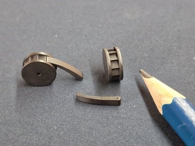
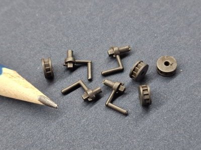
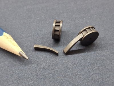
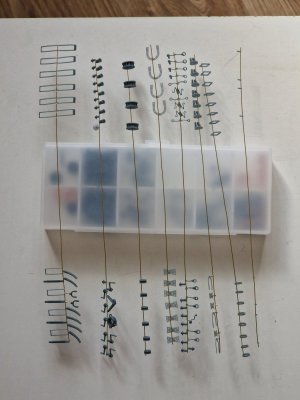
Metalworking. Electroplating (Electroforming), Copper Plating, Soldering, Blackening. Making: cannons anchors rims hinges by serikoff

Beim ersten Lesen deines Berichtes ist man einfach nur sprachlos. Die Fülle an Hinweise, Tipps und genialer Lösungen ust überwältigend. Beim zweiten Lesen erkennt man deine präzise Vorgehensweise. Beim dritten Lesen wird die Motivation geweckt,es Dir gleich zu tun. Deine Arbeit motiviert und zeigt einen ganz anderen Weg zu einem wunderschönen Modell. Du zeigst Wege , die einem normal verschloßen sind. Nachvollziehbar, sehr gut Schritt für Schritt erklärt. Sehr lehrreich dein Bericht und die Einzelergebnisse sprechen für sich. Danke fürs Zeigen.
 
You're holding on too tight, Sergey. It was a little joke.
English isn't my native language, and the translation made it seem more sarcastic... that all the effort isn't worth it when it can all be done much more easily in a couple of days, and that devalues all my work. (Although I understand that I may be overcomplicating things, but I do it the other way around to make things as simple and quick as possible, without physical effort.)

Beim ersten Lesen deines Berichtes ist man einfach nur sprachlos. Die Fülle an Hinweise, Tipps und genialer Lösungen ust überwältigend. Beim zweiten Lesen erkennt man deine präzise Vorgehensweise. Beim dritten Lesen wird die Motivation geweckt,es Dir gleich zu tun. Deine Arbeit motiviert und zeigt einen ganz anderen Weg zu einem wunderschönen Modell. Du zeigst Wege , die einem normal verschloßen sind. Nachvollziehbar, sehr gut Schritt für Schritt erklärt. Sehr lehrreich dein Bericht und die Einzelergebnisse sprechen für sich. Danke fürs Zeigen.
Vielen Dank. Es freut mich, dass es Ihnen nützlich ist; das motiviert mich sehr, weiterzumachen.
 
English isn't my native language, and the translation made it seem more sarcastic... that all the effort isn't worth it when it can all be done much more easily in a couple of days, and that devalues all my work. (Although I understand that I may be overcomplicating things, but I do it the other way around to make things as simple and quick as possible, without physical effort.)
I understand about translation difficulties. But this is not the day we are meeting for the first time. I am confident you know my character and temperament from our many previous interactions. Communication is difficult on social media platforms - to that end I try to always assume the best of others rather than the worst (though I too sometimes fail in this regard). Peace, my friend.
 
It becomes an issue of using new technology, versus old fashion manual labor to produce parts that are visually identical, and since they are for models, strength is not a real issue.

I like the idea of being able to print and plate something that maybe is to complicated to do by had without many tools.

But on the opposite view, either new or old ways cost for initial setup of equipment and supplies.

I think Doc K just likes to drill things for the fun of it, like he does at work! And he keeps it up at home on the models.
 
I understand about translation difficulties. But this is not the day we are meeting for the first time. I am confident you know my character and temperament from our many previous interactions. Communication is difficult on social media platforms - to that end I try to always assume the best of others rather than the worst (though I too sometimes fail in this regard). Peace, my friend.
It becomes an issue of using new technology, versus old fashion manual labor to produce parts that are visually identical, and since they are for models, strength is not a real issue.

I like the idea of being able to print and plate something that maybe is to complicated to do by had without many tools.

But on the opposite view, either new or old ways cost for initial setup of equipment and supplies.

I think Doc K just likes to drill things for the fun of it, like he does at work! And he keeps it up at home on the models.
Sometimes I take my hobby too seriously... because right now it's the only thing that keeps me mentally healthy.
 
Yup, he nails everything, even parts that don't see daylight anymore after finish. Alien But I understand, practise makes the master driller.
Don't forget that I'm a dentist too.ROTF

@serikoff I like this very much, is it possible to do the same with wood or Fimo? I was thinking about ornaments, goldplated.
If the material isn't metallic, you need to coat it with graphite or copper varnish. If you coat it with a sufficient layer, I think wood would work, but I haven't tried it. In theory, it should work on anything less stable. I have doubts about plasticine and other unstable substances. Clay should also work, but I haven't tried it.
 
If the material isn't metallic, you need to coat it with graphite or copper varnish. If you coat it with a sufficient layer, I think wood would work, but I haven't tried it. In theory, it should work on anything less stable. I have doubts about plasticine and other unstable substances. Clay should also work, but I haven't tried it.
Hardw2ood and hardened clay could be possible, hmm that's interesting for making guns for example. Mold, clay, copper.
 
Test #7

This test could be considered both a success and a failure. But I learned a lot from it. Firstly, the brightener in the solution is a consumable and doesn't last forever. Essentially, I don't really need the brightening agent itself (the part will be sanded and polished anyway), but I need it to quickly coat the graphite with copper and create a smooth, even surface without the sandpaper effect. Since many of the parts have very complex shapes, sanding all the surfaces is physically impossible. Therefore, the surface must already be smooth and even.

Alert 2585.jpg

Without a brightener, the copper lays down very slowly and rough, and is also very uneven. This means that some parts may already be coated, while others haven't started yet, and that's probably the worst part. I also changed the concept for creating the support structure. I won't be using the one in the photo above.
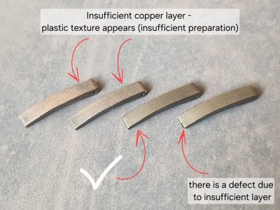
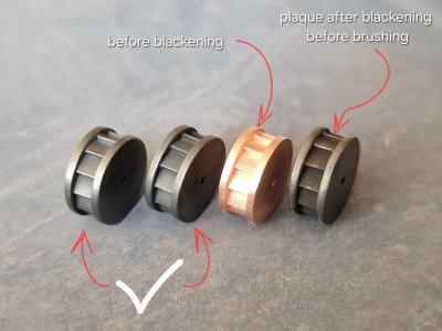
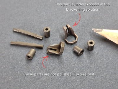
Ultimately, due to the uneven start and the very long process without a brightener (I'll tell you which one in the next test), I stopped this test, and the results were as follows. The parts that didn't start to coat with copper began to deteriorate due to prolonged exposure to the solution, and these parts were rejected. Those that were coated with a thin layer didn't allow for proper sanding, and the plastic texture became apparent (plus, you need to prepare the plastic surface better). And even where the coating was quite good, there were still spots that closed up late, and due to the difference in layer thickness, it was impossible to determine where and to what thickness to sand. That's why there were bald spots on these parts. But a few details still turned out pretty well. I blackened them. I used BrassBlack diluted 1:3 with water and exposed for 15 minutes, removing the film with a brush as I went. Then I rinsed thoroughly, dried for a long time, and removed the film with a toothbrush.

Alert 2586.jpg

Alert 2587.jpg

Overall, I was pleased with the result. The detail, color, shine, and texture of the metal are all very good. I've now ordered some gloss enhancer and copper varnish, and I think the next test will be even more interesting and as close as possible to the result I'm trying to achieve.


Test #8

This test was supposed to be the final one, but due to my mistake, everything went awry. The culprit (this is a preliminary conclusion) was the negative terminal. More on that later, but for now, let's take it one step at a time.

Alert 2593.jpg

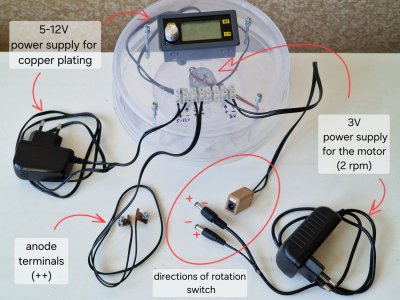
As I mentioned, I replaced the motor's power supply with a 3-volt one. This allowed it to rotate at 2 RPM (instead of 3.3). Because of the high rotation speed, fluid turbulence was causing grooves to form in the parts with holes, which shouldn't happen at low RPMs. I soldered two plugs to this unit, but reversed their polarity. Now, when I plug one plug into the connector, the motor rotates in one direction, and when I plug the other plug in, it rotates in the other direction. I couldn't think of any other quick way to reverse the motor.

Alert 2594.jpg

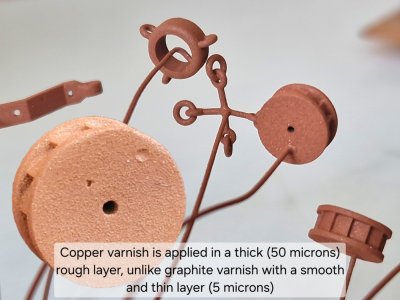
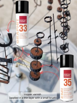
I also bought copper varnish... and here I encountered the expected catch. The layer thickness of graphite varnish is 5 microns. But copper varnish is 10 times thicker...

Alert 2595.jpg

I coated a test sample and realized that this varnish wasn't suitable for our purposes. So, after applying the graphite layer, a day later, I brushed on stripes of copper varnish. This creates areas of greater conductivity so that the parts are coated with copper directly along these stripes, and then the copper will cover the graphite faster, not just from the growth zone, but from the entire strip of copper varnish. That was the idea.

Alert 2596.jpg

Alert 2597.jpg

Alert 2598.jpg

This time, I placed the parts not individually, but on shared holders, which is very convenient. And by the way, to accurately calculate the surface area of each part, you can find this information in Blender, allowing you to set the exact amp value instead of guessing based on the dimensions.
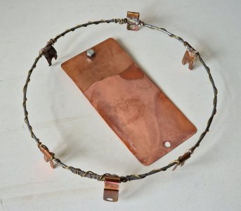
I also soldered all the terminals to a single brass wire, as they were regularly falling off the steel ring. I also drilled a hole on the other side of the plate so I could adjust its position for uniform flow.

Alert 2599.jpg

And now, the most interesting part. Brightening agent. This is a component in the liquid that evens out the copper layer, makes it smooth (shiny), accelerates the copper plating process, and makes it predictable and expected. BUT! This substance must be used in a specific quantity! Exceeding the dosage will lead to dire consequences, ruining both the batch and the solution.
Thiocarbamide CH₄N₂S / SC(NH₂)₂ Thiourea.
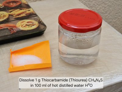
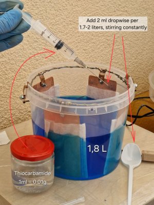
Different sources provide different information on how much is needed for one liter. Some say 0.04 g, somewhere 0.06. But since I didn't know how much was left in the solution and didn't want to take any risks, I added 0.02 g per 1.78-1.8 liters. To make it easier to add very small doses, I measured out 1 gram and dissolved it in 100 ml of hot distilled water. Thus, in my case 1 ml = 0.01 g of substance.

Alert 2600.jpg

Alert 2601.jpg

Add very slowly, drop by drop, stirring well. Then let it settle and completely diffuse.

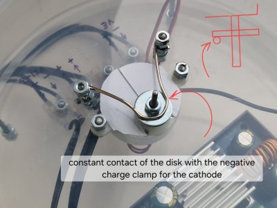
Now about the errors! I used a bearing to transmit current to the rotation axis... and while the rotation was at 3.3 rpm, the current fluctuated slightly due to the balls turning in the bearing, but relatively little. But when I reduced the speed to 2x, the voltage surges became huge, not 0.1-0.2 A, but could fluctuate between 0.4 and 1.8 A... and I only noticed this at the very end... ...and this is what it led to.

Alert 2604.jpg

The components on the upper levels, where the contacts were closest to the voltage surges, were all damaged. This wasn't immediately apparent.

Alert 2605.jpg

But when I started processing the details, the top two levels fell apart in my hands.

Alert 2606.jpg

Alert 2607.jpg

The copper was so brittle that it seemed like dried sand crumbling away. At first, AI and I assumed it was due to Thiourea, or rather its high concentration (although, in fact, I think we should have added more, but that still needs to be tested). But after analyzing the entire situation, we hypothesized that it wasn't the cause, but rather the enormous voltage surges from the bearing's rotation. This was confirmed by the fact that Thiourea (the shine agent) is organic, and it sinks downwards under the force of gravity...

Alert 2608.jpg

...and that fog at the bottom—that was most likely all the Thiocarbamide concentration. And here's my second mistake! Although the parts were rotating, it was at such a low speed that the liquid barely moved, and all the organic matter settled to the bottom. Most importantly, it saved all the lower parts.

Alert 2609.jpg

It's a fact that the bottommost layer was slightly swollen from excess copper plating, but it had just the right texture. The second layer, however, remained shiny but had some minor coating defects. The middle layer also lost its shine but became rougher. BUT! All of these layers were made of very strong copper. It could bend without crumbling. This means that the copper's fragility isn't due to the additives, but only to current surges. Stirring the solution during the copper plating process is essential. Rotating the parts prevents them from being coated unevenly. Stirring the solution ensures that all layers are of uniform concentration. And of course, a stable current is required, without surges or interruptions.

Alert 2602.jpg

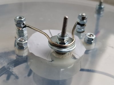
That's why I replaced the bearing with a disc, which the entire surface of the bracket constantly rubs against, and it should transmit current without surges.

Alert 2603.jpg

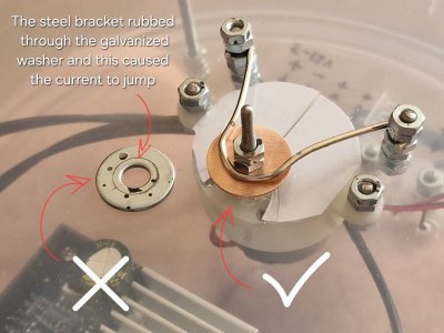
FIX! I ended up replacing the washer and bearing with copper ones, as the previous one had worn through due to a steel clamp, and the metal underneath the galvanized surface was oxidizing, causing voltage surges to return. After replacing it with a copper one, the voltage surge issues completely disappeared. I lubricated the contacts with sewing machine oil.

Alert 2603ы.jpg


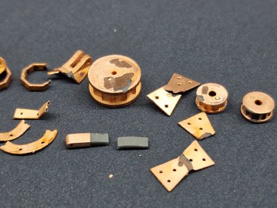
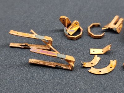
Now I want to show you the results. I'm not 100% satisfied yet, but given the potential, I understand what they could be. But even this result is quite good. I blackened the parts. I sanded some, and not others, to get a feel for how each surface would look. But conclusions have been drawn, and I hope the next test will finally be conclusive... and then it's just a matter of manufacturing all the parts using this algorithm...

Alert 2610.jpg

Alert 2611.jpg

Alert 2612.jpg

Alert 2613.jpg
 
Last edited:
Einfach genial. Wie aus dem Lehrbuch! Ich habe noch nie soviel über Galvanik und Oberflächenbeschichtung gelernt, wie in diesem Baubericht.
 
Hi Sergey,
You've gone to a lot of trouble to stir everything very slowly so as to not create a "swirl" effect. Did you ever consider using an aerator like that in an aquarium to stir up the solution? this would give very good stirring (actually agitation) and would be totally random motion. You can even adjust the airflow to regulate the amount of agitation
 
Einfach genial. Wie aus dem Lehrbuch! Ich habe noch nie soviel über Galvanik und Oberflächenbeschichtung gelernt, wie in diesem Baubericht.
Vielen Dank. Ironischerweise ist es erst vor Kurzem passiert, und ich wusste vorher nichts über Galvanik, aber das Thema hat mich fasziniert, und ich hoffe, die Ergebnisse werden den Zeitaufwand rechtfertigen.

Thank you very much. Ironically, it's recent and I knew nothing about galvanics, but the topic has intrigued me, and I hope the results will justify the time spent on it.

Hi Sergey,
You've gone to a lot of trouble to stir everything very slowly so as to not create a "swirl" effect. Did you ever consider using an aerator like that in an aquarium to stir up the solution? this would give very good stirring (actually agitation) and would be totally random motion. You can even adjust the airflow to regulate the amount of agitation
Thank you for your feedback. It's an interesting idea; I've seen it somewhere before. I need to think about how to organize it. The reservoir isn't that long, so I'm worried about the flow causing problems. But I need to try it.
 
Test #9

This test was supposed to be the last one, and it essentially was, but... not in that it was effective, but rather... it confirmed some of my suspicions, and only the next, 10th test finally yielded the result I wanted. But as an experiment, I'll briefly describe what went wrong.
First, the large number of prepared parts... If there are a lot of parts, you need a larger tub or you need to scale down the wood with the parts... but we always want everything at once...

Alert 2641.jpg

Alert 2642.jpg

The second point is the high accuracy of the parts. Also, despite the urge to do everything at once, I have to redo it, as there are minimum distances that can't be ignored. Like the minimum distance to the bottom of the bath. I'll cover all of this in detail later in the 10th test. Here, I'll focus more on the errors.
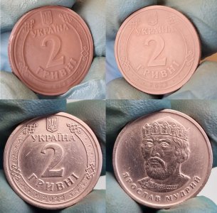
Another point... copper deposits differently on metal and graphite! And using metal (coins, like I did) isn't indicative. I did a test on coins and it was perfect, but with graphite, everything was a disaster, so here's another fact for you.

Alert 2643.jpg

The solution coated the coins perfectly with copper. Every tiny scratch was perfectly captured, and the strength was sufficient when polished with steel wool... but the same solution failed to cope with the graphite...
At first, everything went fine, the copper adhered quickly, but the copper color was a little odd, lacking luster, and the texture seemed off... and then the solution became very cloudy, and I realized something was wrong...

Alert 2644.jpg

Unfortunately, almost the entire batch had to be thrown out.

Alert 2645.jpg

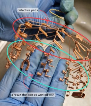
The downside was the formation of artifacts: increased shimmer, hairs, and spikes. But the most important thing was that the copper was extremely fragile, like last time. But this time, two-thirds of the lower parts died. And while the brightener saved the lower parts last time, this time it destroyed all of them (in fact, all of them).
Before this test, I added another 2 ml of Thiocarbamide, and that was a mistake! I thought that since only the lower parts survived last time, it wasn't enough. But too much is worse than even too little. Because it incorporates sulfur and hydrogen into the copper crystal lattice, it becomes porous and very brittle. In the end, I didn't resuscitate the parts from this batch and decided not to play around with the desire to cut costs and speed up the process, so I ordered a new solution.

Conclusion!
I'll tell you how to do it below, but here's some advice on how not to do it! 1. Don't chase speed and quantity. It's better to slow down and be stronger, and less but more effective, than to make a fast, flawed product.
2. You need to buy ready-made solution (mortar) and work with it. And when it loses its performance properties, buy a new one, not reanimate a "dead corpse."

Next, I'll tell you about a successful experiment and what you need to do to ensure everything works. There's a very narrow window of opportunity to do everything right for such small, graphite-coated parts. As you can see, metal is not difficult to coat, and neither are large parts, but the smaller and more numerous they are, the more difficult it is to find the ideal conditions.
But I'm glad that this saga is finally over, and now you just need to keep the mortar working as long as possible (then buy a new one) and do everything without deviations, as best you can, and not chase speed and quantity. Lesson learned.
 
Last edited:
Hi Sergiy
Once again, thank you for doing all this great research and providing the information for us. In your last post you mentioned "mortar". I'm not sure what you are referring to?
 
Hi Sergiy
Once again, thank you for doing all this great research and providing the information for us. In your last post you mentioned "mortar". I'm not sure what you are referring to?
Thanks for the feedback. I'll soon publish an article detailing the finished copper plating solution (mortar) and a detailed analysis of everything else.
 
COPPER PLATING. Galvanizing.

*I duplicated this article on the topic of Alert

So, my galvanizing experiments have finally come to an end. In this article, I'll explain in detail how to copper-plat plastic (SLA, 3D printed), where and how to avoid mistakes, and how to make this process repeatable and, most importantly, effective. Let's get started.

I'll reiterate, this isn't a guide, and I can't guarantee you'll get it right the first time. I'll simply show you how I achieved the result, which is as close as possible to what I originally wanted. (Naturally, based on the trial and error I've made while building my experience.)


Alert 2645.jpg


0. Safety!


Alert 2203.jpg


Always wear gloves! This applies to both plastic, to avoid leaving hand marks on the parts, and copper, to prevent it from oxidizing during all stages of the process, including blackening and beyond.

1. Cathode. Details to be copper-plated.

These parts were modeled in Blender 3D. Incidentally, you can also use it to find the exact area of each part. This is necessary to set the correct current (amperes). This is important, as the result depends on it! Don't confuse volume and area; we need area!

See point 7 for the dimensions and shape of the wood with holders!


Alert 2646.jpg


2. Graphite.

Since plastic doesn't conduct electricity, we need to create a conductive coating using graphite varnish. Apply three very thin layers. Then, use a brush to touch up the connection points between the part and the holders. This will speed up the bonding process between the graphite and the copper and prevent any gaps between the part and the holders.

3. Anode. Copper plates.


Alert 2647.jpg


Ideally, you can find special copper for anodes with phosphorus. Regular copper will do, but a filter is a must!

The anode area (copper plates on both sides!) should be twice the area of the parts with the holders. However, the copper ratio shouldn't be too high, no more than 2.5:1. It's best to make the plates narrow (2-3 cm) and they should be above the liquid level (but only the area in the solution is taken into account!) Before use, be sure to remove the oxide layer on the copper. This can be done with steel wool, sandpaper, or a drill attachment.

4. Filters. Non-woven material.

You need to sew covers from four layers. And be sure to wet them with water and wring them out before use. This material doesn't absorb water well and will stay dry for a long time in the bath.

5. Location and quantity.


Alert 2648.jpg


The anodes should be positioned either opposite each other (2) in long, narrow baths, or in a square (4) in round baths. The terminals should be designed so that the wires do not come into contact with the solution. It's best to use screw-type terminals with quick-release (dovetail) connections.

6. Electronics. Power supplies and step-down control unit.


Alert 2649.jpg


For galvanic applications, you need a step-down converter that can be used to set the current (amps) and volts (volts are set between 2-3V and the converter will automatically control this value depending on the amps). We're only interested in amps; that's the most important thing! This unit, the XY-SK35H, can be purchased on AliExpress. It's inexpensive.

This converter connects the positive terminal (Plus) to the anode (copper plates). I connected it to a terminal inside the case.


Alert 2650.jpg


And the negative contact (Minus) - to the Cathode (parts).

I connected this contact to the motor's rotation axis. I also bought the motor on AliExpress. It's powered by a 3V power supply, which gives it 2 revolutions per minute. In the first versions, I used a bearing in the sliding contact area (a big mistake, as there were huge voltage surges due to uneven ball contact. Then I used a washer, which turned out to be zinc-coated, and when the steel bracket gnawed a groove in it, the contact also began to fail). So I replaced the washer with a copper one and lubricated the contact with sewing machine oil, and the voltage surges have been gone!


Alert 2651.jpg


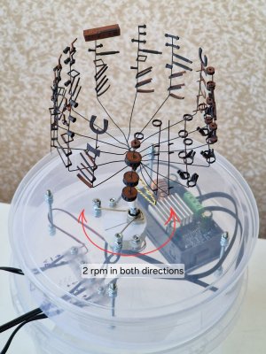
The circuit is simple. I connected the negative terminal to a steel clamp. It rubs against a copper washer, which is screwed to the motor's axis of rotation. A regular wire clamp is screwed to this axis. One side of this clamp holds the axis, and the other side holds the wood components.


Alert 2652.jpg


Alert 2653.jpg


Alert 2654.jpg


7. Distances, dimensions, and shape.

The photo shows the minimum acceptable values. However, it's better to either use a larger tank and liquid, or make the tree smaller. The recommended distance from the bottom is 4.5-5 cm (this is the most important, by the way). From the parts to the plates, 4-5 cm, and between rows and tiers, 2.5-3 cm. However, with these values, I end up with a very small tree and very few parts. I found the minimum value through trial and error. But it's still best to leave at least 4-4.5 cm from the bottom!

So... the tree of parts is installed, the copper plates are polished, washed, dried, and put on damp covers! The tank is washed with soap, dried, clean, and free of streaks and dust. Everything is ready; you just need to add the solution and set the correct voltage.

8. Solution. Ready-made liquid for bright copper plating (acidic).


Alert 2655.jpg


As I've said many times, it's better to buy a ready-made copper plating solution. Making your own is both difficult and expensive, and there's a high risk of getting the proportions wrong and ruining everything. Not to mention, there are many chemicals on the market, and they're not always good or suitable for our purposes. And considering that 2 liters of solution cost 12 euros, I don't see the point in risking making it myself. I bought it at a specialty galvanizing store, and I recommend you look for similar ones. How to store the solution is described below, in section 10.

9. Settings. Current (Amps).

This is perhaps the most important thing after the solution itself.


Alert 2656.jpg


A few words about the motor and rotation. To ensure the copper lays flat and avoids shielding, the wood must rotate. This is achieved with a motor running at two revolutions per minute. Reverse is crucial. Ideally, it should have automatic reverse, but I was only able to make two plugs with different contact polarities, so I reconnect the other contact every 10-15 minutes, thus changing the direction of rotation.

Calculating area and current.

To accurately determine the area of the parts, you can find this value when modeling in Blender, and be sure to add the area of all holders! If the parts weren't modeled, you need to calculate them as accurately as possible using AI.

You need 0.007 A per 1 cm². (The value 0.01 A/cm² is often quoted everywhere, but lower current means denser and stronger copper, longer process times, and less stress on the solution. That's why I derived this value for myself.)
In this case, with an area of 70 cm² (all parts and holders), I set the copper flow rate to 0.5 A/cm², and the copper coated parts up to 1 cm thick in 40 minutes and parts 1.5 cm long in 80 minutes. The copper layer continued to build up for about another 3 hours. The total copper plating time was exactly 4 hours.


Alert 2656а.jpg


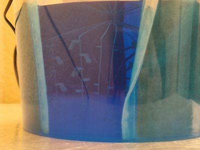
If you shine a flashlight through the solution, the graphite will appear dark, and the areas where copper has formed will be shiny. The area between the graphite and copper (1.5 mm) will be less shiny, as the copper layer there is still minimal.

It is not recommended to remove the parts from the solution. One-time, very brief inspections are permitted. The main thing is to prevent the solution from drying on the parts, otherwise oxidation will occur!


Alert 2656с.jpg


The copper shouldn't be too dull (matte), and it shouldn't have any dark spots or roughness. There also shouldn't be any threads, spikes, or "pimples."

Also, don't partially remove the wood while the unit is running, otherwise the entire stress will fall only on the parts submerged in the liquid!

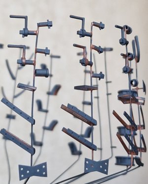
Copper grows stronger and faster on the lower tiers. Therefore, it's necessary to arrange parts of the same shape on the same holder (vertically), and as the layer increases on the lower tiers, you can cut off the lower parts, leaving the upper ones to continue to be coated with copper.


Alert 2657.jpg


10. Cleaning and storage.

This is a crucial step, as the subsequent results will depend on it.

As you can see, the 4-layer filters worked and prevented the bathtub from becoming dirty. The filter plates should be removed from the solution very slowly and carefully.


Alert 2658.jpg


Do not disturb the container containing the liquid during the entire process and after its completion. After removing the parts, seal the container tightly and allow the sediment to settle for 12-24 hours.


Alert 2659.jpg


The filters can be washed, but I recommend making new ones and disposing of the old ones!

The copper plates should be washed with soap and a brush and dried. The oxide film should only be removed before next use, not before storage!


Alert 2660.jpg


The next day, drain the top three-quarters of the liquid using the suction method, without tilting or moving the container! This can be done with a large syringe or tube. Then, pour the remainder into a jar for 3-4 days and leave it there without moving it. During this time, the sediment will settle further, and you need to suck out the top four-fifths of the solution again with a syringe or tube, without moving the jar. Dispose of anything that remains at the bottom.

This sediment will contain the spent organic matter of the brightener and, more importantly, large copper particles (copper dust). When this dust gets on the part, it creates an uneven surface, making the copper rough and brittle. No home filters can stop such small particles, so it's easier to let them settle and discard them.

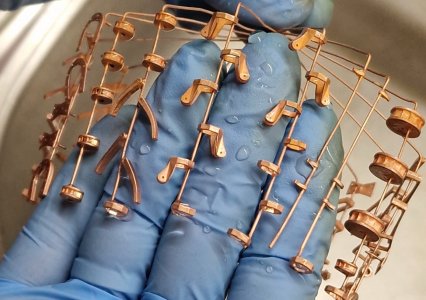
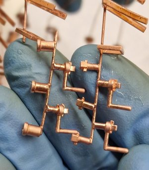
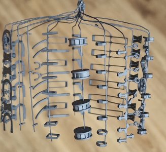
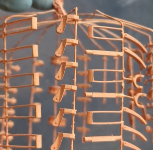
And here's the result immediately after copper plating. This is before any finishing, grinding, and polishing. In the first photo, this is the very bottom tier (it’s a test tier, but it will also turn out great).


Alert 2661.jpg


Alert 2662.jpg


Alert 2663.jpg


Alert 2664.jpg


This copper is extremely durable, easy to process, and can be drawn perfectly. Most importantly, using galvanic processing, you can create metal parts of any complexity and in any quantity with a high degree of repeatability!

 
Back
Top