
-

SUBSCRIBE TO SHIPS IN SCALE TODAY!
The beloved Ships in Scale Magazine is back and charting a new course for 2026!
Discover new skills, new techniques, and new inspirations in every issue.
NOTE THAT OUR NEXT ISSUE WILL BE MARCH/APRIL 2026 -

Win a Free Custom Engraved Brass Coin!!!
As a way to introduce our brass coins to the community, we will raffle off a free coin during the month of August. Follow link ABOVE for instructions for entering.
You are using an out of date browser. It may not display this or other websites correctly.
You should upgrade or use an alternative browser.
You should upgrade or use an alternative browser.
118 Gun French three-decker - Le Commerce de Marseille / L'Ocean - scale 1:72

- Joined
- Jan 21, 2022
- Messages
- 978
- Points
- 403

Thanks. That will be helpfull. One dayA small comment from russian-speaker about Mr Shevelev:
Pear-wood, two layers of linseed oil or Danish oil; and then patina (Idea Liquid Bitumen #741)
")
- Joined
- Jan 21, 2022
- Messages
- 978
- Points
- 403
Update 30.06.2022
I've made Sills. I used veneer pear 2mm+ maple 1mm. I had to put two layers of stain on maple to equate colors.


There's also antother matter. @Uwek on your picture ther're three Stops, but I can't find the lower one on plans and I'm not sure if they're on model of real L'Ocean in Paris museum. On plans almost all port lids are closed so I can't veryfie this.


On the photos of actual model the same situation
I've made Sills. I used veneer pear 2mm+ maple 1mm. I had to put two layers of stain on maple to equate colors.
There's also antother matter. @Uwek on your picture ther're three Stops, but I can't find the lower one on plans and I'm not sure if they're on model of real L'Ocean in Paris museum. On plans almost all port lids are closed so I can't veryfie this.
On the photos of actual model the same situation
Last edited:
- Joined
- Jan 21, 2022
- Messages
- 978
- Points
- 403
Update 22.07.22
I've started making Lintels but it's soo tedious work and wanted to do something more creative. Thus I started making the knee of the head. I only maneged to do couple of elements -[before my saw refused to obey] - and this 4 are the best versions of them(I don't exclude ramendments)
I'm also sorry for this photo quality but for now I haven't found a good place to make them and my room is not good for it

I started from cuting it as one piece to get a hang of it


I've also ran into some problems with dimension. There's suggested pattern for this element along whole ship.


Stern side

But on plans it tapers from 7mm to 5mm. The question is should I make it in 4mm or add some wood or putty allong the keel of resign hull to thicken it to 7mm?

I've started making Lintels but it's soo tedious work and wanted to do something more creative. Thus I started making the knee of the head. I only maneged to do couple of elements -[before my saw refused to obey] - and this 4 are the best versions of them(I don't exclude ramendments
)I'm also sorry for this photo quality but for now I haven't found a good place to make them and my room is not good for it
I started from cuting it as one piece to get a hang of it
I've also ran into some problems with dimension. There's suggested pattern for this element along whole ship.
Stern side
But on plans it tapers from 7mm to 5mm. The question is should I make it in 4mm or add some wood or putty allong the keel of resign hull to thicken it to 7mm?
Last edited:
- Joined
- Oct 15, 2017
- Messages
- 1,197
- Points
- 443

I think since you are pioneering new technology in working with a 3D printed resin hull, it would be very good to have some excess resin materials that you could use to test tasks and materials with it. As an example, I have no idea how or if you can use wood filler with a resin hull. It would be great to test it off the ship. What are the adhesion properties? Just some thoughts.
- Joined
- Jan 21, 2022
- Messages
- 978
- Points
- 403
This is little my fault beacause @SZKUTNIK warned me not to use this hull and wait for corrected one
I can make it thicker by adding some wood to keel, but the question is: if I do it, it will change the shape of hull and this maybe very time consuming to get it back to it's right form
Another solution to this could be reverse ot thickness. Upper part(green) must hold its dimensions but below that I would make it in 4mm
- Joined
- Jan 21, 2022
- Messages
- 978
- Points
- 403
Little update of today's work
I've managed to set up properly my bandsaw and this is 3rd version of this elements of the knee of the head. Dry fitment on photo, but now it's glued in clamps. Connections aren't perfect but it's fine with me. Besides who would choose a scratch build as a first ship model
PS. This looks like I've made only one new element, but infact all three are new
Last edited:

Looking good -
maybe you have to be a little bit more careful with sanding not to round up the edges - they should be sharp, so the joint will look smaller
maybe you have to be a little bit more careful with sanding not to round up the edges - they should be sharp, so the joint will look smaller
Because it is early in the process, and you have made such an attentive approach to the gunport openings, I will speak up and back Uwek on his point. I think it is better to make good joinery, in the "flat" of consistent thickness, and then to taper and do whatever one needs to for the bow. If there's one thing that I've learned about paint, it is that it won't hide these sort of discrepancies; you will always see them, and for me - it would be a point of regret. I offer this always with respect for your personal choices. Just my point of viewLooking good -
maybe you have to be a little bit more careful with sanding not to round up the edges - they should be sharp, so the joint will look smaller
- Joined
- Jan 21, 2022
- Messages
- 978
- Points
- 403
I'm gratefull for everybody's advice. I'm just not on your(most of you guys on sos) level of skill. I remade them with flat joint but I'm not able to go beyond connetcting 3 elements. When 4th is added everything falls apart due to too large gaps. Even in connecting 3 elements I can't make them fit without major gaps.For now my main option is to make it as one piece and this can happen to other things in future. I could be basing my work on plans but some element can be just too hard for me to do, thus they'll be simplified because making them complicated but ugly looking is worse in my point of view. Maybe you disagree?
When I was was considering if I should order hull to such complicated model I was worried about whole prow and my concerns were right.

My small thoughts for @SZKUTNIK to 3d hulls as a semi kit for NEWBIES(the more experinced will manage). Maybe when you have such extras like gun barrels and gun carriages you could also consider some laser cut elements to make it fully semi kit that is easy/ier to assemble. Main efforts on hard to make elements would be on your side. Of course it would cost, but in relation to buying machines and wasting lots of expensive wood it maybe reasonable expense. In my opinion those elements should be(if someone wants them) option as a lasercut + pin rails in 3d print.


When I was was considering if I should order hull to such complicated model I was worried about whole prow and my concerns were right.
My small thoughts for @SZKUTNIK to 3d hulls as a semi kit for NEWBIES(the more experinced will manage). Maybe when you have such extras like gun barrels and gun carriages you could also consider some laser cut elements to make it fully semi kit that is easy/ier to assemble. Main efforts on hard to make elements would be on your side. Of course it would cost, but in relation to buying machines and wasting lots of expensive wood it maybe reasonable expense. In my opinion those elements should be(if someone wants them) option as a lasercut + pin rails in 3d print.
Last edited:
- Joined
- Apr 10, 2020
- Messages
- 373
- Points
- 323

Ahoy!
 Any suggestions????
Something similar to the one below ???


Come back to your drawings - steering wheel, bow stem ... It is no problem to do it as an option to combine laser cut and 3D print.
One can think over this......3d hulls as a semi kit for NEWBIES......
Any suggestions????Something similar to the one below ???
Come back to your drawings - steering wheel, bow stem ... It is no problem to do it as an option to combine laser cut and 3D print.
Last edited:
- Joined
- Jan 21, 2022
- Messages
- 978
- Points
- 403
Not quite.Something similar to the one below ???
The modeler still needs to do all the planking of decks and hull. Every simple elelment on visible deck is done by him, but some very complicated elements like gun barrels,kapstan,steering wheel, bow stem would be an extra option to choose
As for me I'll try to do this elements by myself, but if I'll get caught in a corner I know who to contact
If I may ask, WojtasS, what has been your particular process and choice of tools for cutting to the lines on these bow timbers? Do you possess an electric scroll saw, or are you only using hand tools like a coping saw?
- Joined
- Jan 21, 2022
- Messages
- 978
- Points
- 403
I have electric saw. First I cut around pattern with little margin to polish, then I use this electric belt sandpaper and for final fitment I use this hand file
On this picture I've cut it very close to patern. Usually I leave little more material


On this picture I've cut it very close to patern. Usually I leave little more material
Last edited:
 , great! Full-disclosure: while I am a woodworker who makes furniture, I am a plastic model builder and haven't yet attempted to do what you are now. That being said, I am very familiar with the tools you are using. The first thing I would make certain of is that my bandsaw table is perfectly square to my blade and that the blade is properly tensioned and tracked so that there is no deflection in the cuts.
I think where you may be running into trouble is with this kind of belt sander which, while there is a support behind the belt to work your shapes against, the edges of the belt don't lend themselves to getting neatly into tight corners. It is very easy, using this kind of belt sander, to introduce irregularities to your surfaces, which may be what is causing your gapping difficulties.
If I were attempting this, I would bandsaw close to the lines, as you have done. I would then make up a series of sanding blocks and sticks. The main sanding block should be large enough to manipulate comfortably, and the sides need to be perfectly square to the faces. To the squared edges, I would double-stick tape 100 grit sand-paper. This block, set flat on a flat work surface, is what I would use to fair my convex curves. I would make a corresponding, curved face block that I would use to fair my concave curves. The advantage of these blocks is that you always will maintain squared edges on your parts and the solid backing of the block enables you to shape reliably to your lines.
Likewise, files can be tricky to use. For this sort of thing, I prefer to make sanding sticks to which I double stick my sandpaper. These sanding sticks are for the final tuning of the joint. Patience and a lot of back and forth checking will ensure that you ease into adjacent steps and shoulders without introducing slop, elsewhere in the joint.
This isn't exactly an easy thing to do, but it is certainly an acquirable skill, with patience and practice. The benefit of mastering this skill is that it makes the scratch fabrication and fitting together of the many parts and deck furniture an enjoyable pass-time.
- Joined
- Jan 21, 2022
- Messages
- 978
- Points
- 403
Sth like this?sanding blocks
Kostka szlifierska do modeli z drewna - Artesania Latina 27014
Kup Kostka szlifierska do modeli z drewna - Artesania Latina 27014️ i ciesz się doskonałą jakością!
 modelnet.pl
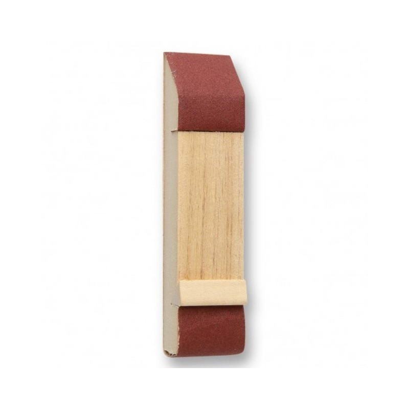
Like mine on last photo?sanding sticks
Would you push sanding element to such block or push block to the sanded element?
Well, what I have in-mind are home-made blocks and sticks where the double-stuck sandpaper is trimmed absolutely flush with the edges of the block/stick; total adhesion of the paper ensures that you won't introduce irregularities to the joint surfaces.
For the most part, I'm pushing the part to be shaped into the block. For ease and better control, one can clamp the block to your work surface, so that you can use both hands to guide the part. Sanding sticks are used, free-hand, much like files. I find that I have more control and precision when using sanding sticks, as opposed to files. Then again, I don't yet own a really good set of needle files that are made for this purpose. The files I have are an old EXACTO set that are good enough for plastic work.
For the most part, I'm pushing the part to be shaped into the block. For ease and better control, one can clamp the block to your work surface, so that you can use both hands to guide the part. Sanding sticks are used, free-hand, much like files. I find that I have more control and precision when using sanding sticks, as opposed to files. Then again, I don't yet own a really good set of needle files that are made for this purpose. The files I have are an old EXACTO set that are good enough for plastic work.
- Joined
- Oct 15, 2017
- Messages
- 1,197
- Points
- 443
What Hubac's Historian is referring to is exactly what I do and use for this type of sanding work. I square up wood sticks, apply double sided tape and adhere sandpaper on both sides, usually 120 on one side and 220 on the other. For some I wrap the paper around the 90 degree corner, but it's not really necessary. See some of my low tech sanding sticks ("crackers") below. It really takes no time to create. Then when needed you peel off the old paper and place on the new. Sometimes not even needing to replace the double sided tape.

Thanks for the visuals!