• Win a Free Custom Engraved Brass Coin!!!
    As a way to introduce our brass coins to the community, we will raffle off a free coin during the month of August. Follow link ABOVE for instructions for entering.

17th Century Ship Design and the Sovereign of the Seas (1637)

The Body Plan
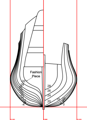
The body plan shows the bends’ shapes. The bends are symmetrical, so once half a bend is drawn, the appearance of the other half is also known. Therefore, only half of each bend is shown on the body plan. The halves representing the bends fore of the midship bend are shown on the right half of the plan, and the halves depicting the bends aft of the midship bend are shown on the left half of the plan.

Shipwrights drew their bends by following an established procedure. This consisted of progressively shrinking the bends as they moved further away from the midship bend. The rising lines told shipwrights where to shrink them (the bends were shrunk at the floor, breadth, and toptimbers), and the narrowing lines told shipwrights how much to shrink them. Consider the upper rising line at the 20th aft bend as an example. The versed sine for this bend (see the section on the aft upper rising line for further discussion) is 0.57 feet, and the narrowing is 1.38 feet. This tells us that the ship’s breadth here is 0.57 feet higher than it is at the midship bend, and its half breadth is 1.38 feet narrower than at the midship bend. Similar subtractions were performed for each rising and narrowing line at each bend drawn on the body plan, and the results were tabled. As the Treatise’s author explains; “The first thing to be done is to calculate and set down in a table the rising
and narrowings of all the bends that they may be in areadiness … The table being made, you may make every other bend out of the midship bend.” This explanation encapsulates the idea of whole molding that was discussed in the introductory material I presented; all bends are simply a modification of the midship bend.

After tabling the appropriate risings and narrowings, shipwrights plotted the relevant heights and widths of the floor, breadth, and toptimbers. This gave them three reference points through which they should draw a bend’s sweeps. In the present case, the radii of the sweeps are those given by Phineas Pett.

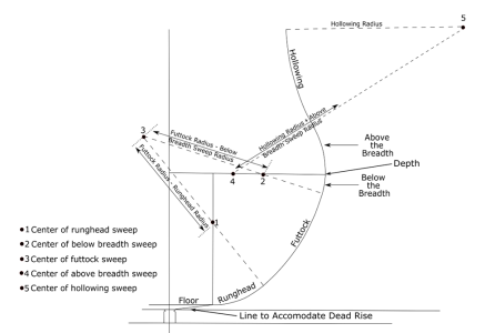
The next task was to find each sweep’s center and boundaries. When this was finished, shipwrights then used a compass to draw each sweep. Describing the procedure is simplest if we refer to Figure 80, and focus on how to find the futtock sweep’s center and its boundaries.[1]

The futtock sweep’s boundaries are found by first marking the radius of the sweep of the runghead along a line that runs up from the floor’s lateral boundary (this mark is point 1 in Figure 80.) A compass is then set to the futtock sweep’s radius minus the radius of the sweep of the runghead, and point 1 is used as a center around which a small arc drawn near point 3 in Figure 80.

Shipwrights then marked the radius of the sweep below the breadth along a line that ran horizontally along the bends’s depth and from its widest point (this mark is at point 2 in Figure 80.). The compass is set to the radius of the futtock sweep minus the radius of the sweep below the breadth, and another small arc drawn near point 3 in Figure 80. The point at which this arc intersects with the arc drawn as described in the previous paragraph is the center of the futtock sweep. The boundaries of the futtock sweep are obtained by drawing straight lines from its center, and through points 1 and 2.

Having found the futtock sweep’s boundaries, shipwrights now set the compass to the radius of the sweep of the runghead, place one of its legs at this sweeps center (point 1 in the figure), and drew the sweep from the floor up to the futtock sweep’s lower boundary. The compass was then adjusted to the radius of the sweep below the breadth, and this sweep drawn down to the futtock sweep’s upper boundary using point 2 as its center. Finally, the compass was set to the futtock sweep’s radius, and the sweep drawn from its upper to its lower boundary using point 3 as the center. If all goes well, the sweep reconciles (i.e., meets) with the other two sweeps.


Figure 80. Drawing a Bend
1758301430055.png
Note: The toptimber rising line typically does not fall at the bend’s top as shown in Figure 79. Rather, the sweep’s center, which is given by the intersection of two arcs whose radii equal the hollowing sweep’s radius and the sum of this radius plus the radius of the sweep above the breadth, is measured at each bend from a point given by the toptimber rising and narrowing lines.

Shipwrights also allotted space for deadrise at the bottoms of their bends. This could be accomplished at and near the midship bend by drawing a straight line from the floor’s lateral boundary to the keel’s top (see80). This became unsatisfactory as the bends approached the bow and, particularly the stern. Here, a reverse curve was often drawn. The Treatise makes the radius of this curve equal to the radius of the runghead. This reverse curve gives the bends of 17th century ships their characteristic V-shaped bottoms.

It is worth noting that the procedure outline above, which is the procedure described by the Treatise, contrasts with John McKay’s description of it. He states that the center of the futtock sweep “is not located by horizontal and vertical measurements. By trial and error, one must find it ….” and that he also found the center of the toptimber sweep “by trial and error.” (9 p. 26)


[1] Notice that some sophisticated analytical geometry underlies how the centers of the sweeps are found. This attests to the mathematical prowess of early 17th century shipwrights.
 

The Body Plan (continued)​

Straightening the Top Timbers​

The top timber sweeps at and near the midship bend were often drawn and built as curved. This created a concavity in them that was called the hollowing (see Figure 81). [1] However, it is difficult to use hollowed timbers along the entire course of the ship. If this is done, the timbers will flare out along the upper decks. Although this was acceptable fore of the midship bend (and, as previously discussed, this “flaring” is incorporated into the present plans), it was not acceptable aft of it. To counter this, the Treatise tells us that the amount of hollowing should gradually decrease as the timbers move away from the midship bend. This straightening is mathematically equivalent to gradually increasing the radius of the hollowing sweep until it becomes infinite. It is possible that this eventually gave rise to the idea of changing the radii of all the sweeps as the bends approach the bow and stern.

Figure 81. The Hollowing
1758633059615.png

Where the straightening should begin and end is a surprisingly complex topic that has not been given much attention. This is illustrated by the difficulties we face when straightening the top timbers aft of the midship bend. One challenge is that the amount of straightening between adjacent top timbers cannot exceed the amount of narrowing between them (if it does, an aftwards top timber will be wider than the timber before it). However, on the current plans, the ship does not appreciably narrow until about the middle of the half deck. This means the straightening must start relatively far aft of the midship bend. On the other hand, we cannot start it too far aft. If we do, the top timbers will flare out before we start straightening them. The decision on where to start the straightening is made more complex because it is influenced by the top timber sweep’s radius. If the radius is small, we must start the straightening relatively close to the midship bend but, if it is large, we can start the straightening further aftwards. Finally, where the top timbers begin to flare out is influenced by the heights of the upper decks. Flaring tends to occur when the decks are higher. This is particularly evident on the 3-decked ship like the Sovereign, whose roundhouse is very high. It is not clear that shipwrights had any specific rules for balancing these considerations. They may have decided where to start and stop the straightening based on their experience.

The Treatise describes two procedures for straightening the top timbers. Neither is fully satisfactory. One of them does not produce any fair lines aft of the midship bend, and the other does not take the abrupt increases in the timbers’ heights at the breaks of the decks (Kirsch, 1988, p. 198), so fairing is required. More sophisticated methods would be developed later in the seventeenth century. They were developed in no small part by a descendent of Phineas Pett whose name was also Phineas. (Moneypenny & Antscherl, 2021) However, to stay closer to the early seventeenth century, I used the second of the Treatise’s procedures. The result is that the straightening on the current plans begins at about the middle of the half deck (which is aft bend 16) and the top timbers become completely straight at the fore end of the roundhouse (which is aft bend 32).

I have straightened the timbers forward, the same way they were straightened aft. They begin to straighten at the 16th bend forward, and the straightening proceeds as if there were 32 fore bends. This makes the top timbers symmetrical fore and aft of the midship bend. Also, and as previously noted, this causes the bends to flare near the catheads.

With the straightening of the top timbers now complete, we can draw the body plan. This is shown in the figure below.


1758633147979.png


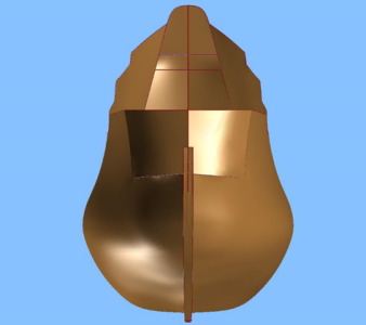
The figure below shows a crude 3-dimensional representation of the hull that results from these plans. I am always struck by how round this ship is. It’s an expression of the 17th century preference for curves that’s about as far away from a Yankee clipper as you can get.
1758633314828.png
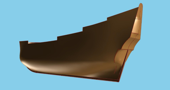
The picture below provides another crude view worth looking at. Notice how the stern galleries are rounded, and project aft.
1758633364433.png

References​

Kirsch, P. (1988). The Galleon. London: Conway Maritime Press, Ltd.

Moneypenny, E., & Antscherl, D. (2021). A Restoration Yacht's Design Secrets Unveiled: An examination of a ship model with reference to the works of William Sutherland. The Mariner's Mirror, 107(2), pp. 164-187.


[1] Not all ships used hollowed top timbers. Deane does not address these timbers, but Bushell’s are straight. Although the Treatise’s author prefers hollowed top timbers, he also acknowledges that they can be straight.
 
Concluding Remarks

When I started this project, my intent was to draw a set of plans complete enough to allow me to start building a model of the Sovereign of the Seas. Now that I’ve posted about the hull’s primary features, this is pretty much done, so I’d really like to turn my full attention to the model. This means I won’t be making any more posts in this thread. However, I can recommend further reading. Anderson’s book (Anderson, 1994), “The Rigging of Ships in the Days of the Spritsail Topmast,” is an excellent source, and DARIVS ARCHITECTVS thread on this site (see https://shipsofscale.com/sosforums/...deagostini-beyond-believable-boundaries.6365/) is the most detailed work I have seen. That having been said, now is the time for some concluding remarks.

It is difficult to recommend the two published books on this ship. One is by James Sephton, and the other by John McKay. Although Sephton does not provide plans, he provides information that can ostensibly be used to prepare them. However, he does not discuss whole molding, or the rising and narrowing lines. A reconstruction of this ship cannot be undertaken without this information. Sephton also relies too much on previous, erroneous plans for the Sovereign without evaluating them, recommends a “reconstruction draught” that does not represent the Sovereign as initially designed or launched, some of the dimensions in his tables are incorrect, and he uses an incorrect midship bend. His most frequently repeated error is in distribution of the Sovereign’s guns.

McKay’s book, which has been relatively popular of late, is wonderfully illustrated, and provides much more detail than Sephton’s. Unfortunately, much of that detail is incorrect. To my mind, the most serious mistakes in this book are his square tuck stern, an incorrect midship bend, and putting falls in the decks. However, the book contains numerous other errors, including (but not limited to) incorrect gun carriages and a misplaced tiller.

As I said at the outset, the present plans are an approximation of the Sovereign. I am not convinced that every aspect of it can be reconstructed as originally designed. Nevertheless, the present plans incorporate every dimension the Sovereign’s designer, Phineas Pett, provides. I am not aware of any other plans that do this.

Because of the uncertainty surrounding this ship’s initial design. I have tried to point out where this occurs by noting that some aspect is speculative or uncertain. The good news is that modelers can modify these aspects in ways they find more to their liking. The bad news is that they have no certain direction here. Therefore, I have also tried to explain why I made certain decisions. This allows modelers to evaluate my plans, something that is difficult to do from only drawings. The difficulty, though, is that this approach requires a lot of words, and does not allow many pictures. I understand that this thread reads more like a textbook than a build log. Thank you for reading it.
 
CharlieT, I want to thank you and say how grateful I am that you posted such an in-depth treatise on HMS Sovereign of the Seas. First Place Metal My only regret is not having you as a source for information when I was forming the hull of my model 4 years ago. Even so, your treatise has been incredibly informative, and all of us who love the Sovereign are in your debt. :D

Most researchers stop writing just as they get done describing the hull as you have. It is possible for you to continue this thread by delving into the internal deck layout, masts, sails and rigging, insomuch as there is source information available that is reliable for early 17th century vessels? Ship-1
 
Last edited:
Hi Charlie:

I also would like to express my appreciation of your work: researched at length, and set out with care. There is a great deal of use here, and all of it will be of use to anyone attempting their own reconstruction of the Sovereign. I am sure that you will not be the last! I wish you all the best with your model, and may she be a joy to all who behold her (especially you, who will be aware of the parts which you look at and think 'Why did I not do that a little differently?', which no-one else will be aware of!)

I most definitely agree with your assessment of the value of both Sephton's and McKay's works: far too many flaws to form any reliable guide to the subject. Which is most unfortunate. Sephton's habit of rarely stating a source for his many comments and assumptions is especially annoying; and McKay's ridiculous stern is a parody derived from no source at all.

Many thanks indeed!
 
Last edited:
CharlieT, I want to thank you and say how grateful I am that you posted such an in-depth treatise on HMS Sovereign of the Seas. First Place Metal My only regret is not having you as a source for information when I was forming the hull of my model 4 years ago. Even so, your treatise has been incredibly informative, and all of us who love the Sovereign are in your debt. :D

Most researchers stop writing just as they get done describing the hull as you have. It is possible for you to continue this thread by delving into the internal deck layout, masts, sails and rigging, insomuch as there is source information available that is reliable for early 17th century vessels? Ship-1
Hi Kurt;

I too share your admiration of Charlie's work here, and leading on from this, I would like to attempt some answer to your question re the cabin layout.

The simplest answer is that, most regrettably, 'We do not know.'

Every surviving record from the Sovereign's build, repairs and service which I have been able to locate makes zero mention of her internal layout. Her list of dims gives us one fact, which is that she was flush-decked, as Charlie has shown her here. And that's it!

One great regret is that there exists a survey of the cabins of the ships moored at Chatham, dated from the early 1640s. The Sovereign is not amongst them, unfortunately; presumably because she was moored further downriver, at Gillingham, in deeper water, along with the Prince Royal, which is also missing from the survey. If only!!

We can, therefore, only rely upon extrapolation from what we know of other ships.

Her nearest contemporary in size and layout was the Prince. In her case, there is some information available, which enables a list of her main cabins, and hold divisions to be made. I have not yet done this, but will be; this will then be used to illustrate the cabins of the Sovereign in a reconstruction of my own which I am attempting.

I would also like to add something, which I believe will be of interest, although not directly related to the Sovereign. This is that if all goes as planned/hoped, there may well be an article in a forthcoming issue of the Mariner's Mirror which discusses the decoration of Elizabethan warships, which gives some interesting information about where the Sovereign's decorative works may have been derived.

Ratty
 
Thank , you both for you kind comments.

Kurt, to be honest with you, I have not gone much further in my research on the Sovereign. As Bilge Ratt points, out, we don't know anything about the Sovereign's internal layout. One reference you might look at for this is Frank Fox's book, Great Ships (Conway Maritime Press, 1980). It has the layout of what he calls a "typical" first rate, and it is based on the Establishment of 1673. Obviously, this won't be exactly like the Sovereign, but it will give you information not in McKay's book.

Asking for rigging is a tall order. Lavery's publication of Deane's Doctrine contains a list that gives the numbers of deadeyes and the yards of canvas, etc. on the Sovereign, but is not complete. Keltridge (avaialble at https://repository.library.brown.edu/studio/item/bdr:6feamztx/) gives a more extensive list for first rates. It is not specific to the Sovereign, but I wouldn't be surprised if a list specific to this ship exists somewhere. However, it will be difficult to find a source that tells us now all the ropes and blocks were connected. For this, I'd recommend the Anderson book I mentioned in the concluding remarks. The result will be rigging that's generic, but it will be historically accurate.

You might also want to supplement the information in Anderson's book with information in James Lees The Masting and Rigging of English Ships of war, 1625-1860 (Conway Maritime Press, 1979). An appendix in this book contains the lengths and diameters of the Sovereign's masts and yards derived from a document from 1640. Unfortunately, the original document does not contain the diameters, so Lees calculated them from another contemporary source. Therefore, they are an approximation.

A source from 1660 gives the distances of the mast centers from the rabbet of the stem, as measured along the lower gun deck. These are 13 feet 4 inches for the foremast, 87 feet for the mainmast, and 138 feet 9 inches for the mizzen. These are all based on a deck that is 167 feet 9 inches long, which may not be the deck length on your De Agnosti model. Also, that model might not use the stem rake that Pett gives us (38 feet). If this is the case, you'd have to settle for simply using the mast distances as I've given them, or perform some fancy calculations.

Again, I'm sorry I can't be of more help here, but I have not yet looked into these things in any depth.
 
Hi Kurt;

I too share your admiration of Charlie's work here, and leading on from this, I would like to attempt some answer to your question re the cabin layout.

The simplest answer is that, most regrettably, 'We do not know.'

Every surviving record from the Sovereign's build, repairs and service which I have been able to locate makes zero mention of her internal layout. Her list of dims gives us one fact, which is that she was flush-decked, as Charlie has shown her here. And that's it!

One great regret is that there exists a survey of the cabins of the ships moored at Chatham, dated from the early 1640s. The Sovereign is not amongst them, unfortunately; presumably because she was moored further downriver, at Gillingham, in deeper water, along with the Prince Royal, which is also missing from the survey. If only!!

We can, therefore, only rely upon extrapolation from what we know of other ships.

Her nearest contemporary in size and layout was the Prince. In her case, there is some information available, which enables a list of her main cabins, and hold divisions to be made. I have not yet done this, but will be; this will then be used to illustrate the cabins of the Sovereign in a reconstruction of my own which I am attempting.

I would also like to add something, which I believe will be of interest, although not directly related to the Sovereign. This is that if all goes as planned/hoped, there may well be an article in a forthcoming issue of the Mariner's Mirror which discusses the decoration of Elizabethan warships, which gives some interesting information about where the Sovereign's decorative works may have been derived.

Ratty
Thank Ratty! I suspected there are huge gaps in information for all these early ships. I'm looking forward to your article on ship decorations from Elizabethan times.
 
Thank , you both for you kind comments.

Kurt, to be honest with you, I have not gone much further in my research on the Sovereign. As Bilge Ratt points, out, we don't know anything about the Sovereign's internal layout. One reference you might look at for this is Frank Fox's book, Great Ships (Conway Maritime Press, 1980). It has the layout of what he calls a "typical" first rate, and it is based on the Establishment of 1673. Obviously, this won't be exactly like the Sovereign, but it will give you information not in McKay's book.

Asking for rigging is a tall order. Lavery's publication of Deane's Doctrine contains a list that gives the numbers of deadeyes and the yards of canvas, etc. on the Sovereign, but is not complete. Keltridge (avaialble at https://repository.library.brown.edu/studio/item/bdr:6feamztx/) gives a more extensive list for first rates. It is not specific to the Sovereign, but I wouldn't be surprised if a list specific to this ship exists somewhere. However, it will be difficult to find a source that tells us now all the ropes and blocks were connected. For this, I'd recommend the Anderson book I mentioned in the concluding remarks. The result will be rigging that's generic, but it will be historically accurate.

You might also want to supplement the information in Anderson's book with information in James Lees The Masting and Rigging of English Ships of war, 1625-1860 (Conway Maritime Press, 1979). An appendix in this book contains the lengths and diameters of the Sovereign's masts and yards derived from a document from 1640. Unfortunately, the original document does not contain the diameters, so Lees calculated them from another contemporary source. Therefore, they are an approximation.

A source from 1660 gives the distances of the mast centers from the rabbet of the stem, as measured along the lower gun deck. These are 13 feet 4 inches for the foremast, 87 feet for the mainmast, and 138 feet 9 inches for the mizzen. These are all based on a deck that is 167 feet 9 inches long, which may not be the deck length on your De Agnosti model. Also, that model might not use the stem rake that Pett gives us (38 feet). If this is the case, you'd have to settle for simply using the mast distances as I've given them, or perform some fancy calculations.

Again, I'm sorry I can't be of more help here, but I have not yet looked into these things in any depth.
Hello CharlieT, I understand that all we can use is a generic rigging type from this time period. Can you add any details you suspect may be used on the Sovereign beyond what RC Anderson documented? I have all the other books you have referenced but am loathe to use them as sources because of the difference in time period. It appears we have reached the end of available historical information regarding construction details on the Sovereign. From here on, building a model is mostly within the realm of interpretation.

I hope you will post a build log of your model of HMS Sovereign of the Seas, because it will generate more great discussion!

Thanks!
 
Last edited:
Sorry, Kurt, but I really can't authoritatively comment on what Anderson may not have documented. I'm years away from thinking about the rigging in detail.

As to a build log, well, I've certainly thought about it, but I am not the most skilled builder in the world. I probably won't make a decision on whether I will post one until after I have the garboard strake on the ship. Then, I should know whether my model will be embarrassing.
I'm pretty far from rigging too as you know, but I do have a nice resource put together by another modeler who delves into rigging. You may already have seen it. See attached.
 

Attachments

Thank you! Yes, I'd seen it but have not really studied it. I've downloaded your attachment for when the time comes.
 
Back
Top