17th Century Ship Design and the Sovereign of the Seas (1637)

Hi Barry;

Just to help with understanding the difference, here is a part of Van de Velde's drawing, which I believe was possibly made in 1660, and a part of Payne's engraving, showing the ladder mentioned. There is obviously quite a bit of difference between the two.

Ratty

1737321556607.png

1737321613698.png
 
Hi Barry;

Just to help with understanding the difference, here is a part of Van de Velde's drawing, which I believe was possibly made in 1660, and a part of Payne's engraving, showing the ladder mentioned. There is obviously quite a bit of difference between the two.

Ratty

View attachment 496252

View attachment 496253
Do you have the rest of the van de Velde drawing at that scale? I'm looking for that image in high resolution for decoration research.
 
Hi Kurt;

I regret that I am not able to share any further images of the drawing. At this resolution I have a series of partial images. The whole image is of lesser quality.

I obtained these perfectly legally, but due to them being required for another project, I am not currently able to distribute any images.

Sorry for the disappointment.

Ratty
Is a high resolution image available for sale from the owner? How does one obtain such an image for research "legally?"
 
thanks ratty i really do appreciate , its just a question of choosing which way to go really , am reading the sovereign of the sea book by james sephton , really goes into about her construction , wood used how and some much more , jsut started few day ago , if you have not read it yet am happy to send pages that specify the construction of the haul etc....
 
am trying something different for the haul , first layer of planking with ramin strips 0.2x 6 hard wood hard to bend . but better for shaping the haul and sanding it into real good shape , finger crossed, second planking with beech bellow the waterline , that or elm , as it was during this period a good choice of wood for ships bellow the waterline and oak strip all above
 
Hi Barry;

Thanks for mentioning Sephton. I have his book in my library, and have read it twice. However, I find it to contain many inaccuracies; as does McKay's more recent book; which, while excellently drawn, and a useful source in some areas, contains many absolutely shocking errors, which can only have arisen from a profound gap in the author's knowledge of ships of this period, however well he knows ships of later periods. Frank Fox summed it up very well in his comments made upon its publication.

Regarding the wood you are considering for the planking, I would be wary of using any wood with a noticeable grain pattern. At scale sizes this simply looks very wrong. Both oak and elm were certainly used for ship building, but both fall into the category of wood to avoid for models, simply because of the large grain pattern. I have never seen any contemporary models with either of these timbers visible anywhere.

Hi Kurt;

As far as I am aware, the owner of the Van de Velde drawing does not have, nor sell, images of it. There are none available that I know of.

Ratty
 
Last edited:
Hi Barry;

I am glad that you find my comments helpful. That is one of the main reasons for joining a forum like this. Most questions can find an answer. Some of mine have been answered by helpful contributors in the past, and I felt the same gratitude to them.

Ratty
 
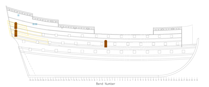
I've finally gotten around to revising the plans based on the new dimensions I mentioned a couple of months ago. The new dimensions tell us that the ports were five feet from that water amidships, an additional foot from the water forward, and an additional 18 inches from the water abaft.

This obviously affects the previous decks, and has a cascading effect. Below is a summary of the major changes I have made. I have included links to where these changes appear in this thread.
I've also taken the opportunity to redraw the plans in LibreCAD. The new drawings are more accurate than the previous ones, but the downside is that they don't show up as well when imported into this thread as a .jpeg or .png file. So, I've attached a PDF file that summarizes the drawings so far. It shows up better than the image files.
 

Attachments

Last edited:
Allow me... One can still make out the deck locations shown by the dotted lines. This is one of the most helpful images for modelers, CharlieT. You can take dimensions off it to get the proportions correct for all the major elements, such as the galleries relative to the internal decks. Just what I need! My current model may have dimensions which don't correspond exactly to this drawing, but the placement of features can be adjusted to match it fairly close. Thank you! :D
1740876845441.png
 
Last edited:
HI KURT AFTER25DAQS 2DAAGED TRANSPOR VAN A PUNCHED OUT AIDE CHASED WITH WHEEL CHAIR OK YES THERE ARS/IS SOME HEALTH/MENTALL
I WILL NOT GET INTO THE WHOLE FUCKING MESS I WAS IN ASSISTED LIVING FACILITY FOR OVER 2 YEARS THROUGH THEM WOUND SPECILIST CAME BY 3 TIME A WEEK IT STARTED WITH A FINGER NAIL SIZE TODAT IN BED HEALING FOR A QUARTEOLE AL AIDES WHATEVER NURSE SEDWICH KNEW PICTURS TAKEN WELL HE CONTNUED TO PUT PATCHES PATTING ME ON THE SEE YOU FRIDAY THIS IS BAD, VERY, VERY BAD USA MEDICINE QUICKLY GOOD STUFF MY DR HARTER TOLD SEWICK AND ADMINISTATOR THE ONLY WAY THE WOUND WILL HEAL IS IN A HOSPITAL BED THEY SAID BULL SHIT GUES WHAT I AM M IN A HOSPITAL BEDABOUT 14 HOURS A DAY OTHER SHIT WILL CUT ITOUT OF SEDWICH FOUND THROUGH CATHOLIC CHARITES PLACE RIGHT NOW MYBE 67 PATIENCE PROBALLY 10 AIDES NURSES SOMTIMES OK HRE IS SOM OF HELP THE COMUNITY CAN HELP EXAPLE SEDWICH I FELT SUBCONCILY IT WAS TEMPORY THIS PLACE IS PERMANT NO GUES WORK WILL LIVE AND DYE HERE THROUGH JUSEUS CHRIST I AM WHERE HE WANTS ME TODAY I HAVE TO BE NAT LEASE FOR A WHILE VERY CAREFUL NOT TO FUCK MYSELF UP MENTALL GOING TO HIGH OR TO TOLOHOLDING THAT KURT I HOPE YOU DO NOT MIND THE CONVERSATION IF SO WILL NOT DWEL WHERE NOT, BUT IN MY COFORT I HAVE GROWN VERY VERY OF RESEARCH ABSORB BY IT,,, YOU WALDAMER CHARLIE T KORUN, OLHA SO SO MANY EXPERTS I A A TOTAL AND COMPLETE ILLTERATE ON THIS BUT I SURE AS HELL WANT MORE I HAVE SOME THOUGHTS, IDEAS WILL NOT COMUNITATE UNTIL IT IS OK PLEASE HIT ME BACK ANSWER PLEASE. GD BLESS STAY SAFE ALL DON
 
Section VI: The Rising and Narrowing Lines (continued)

The Rising Lines​

The two rising lines most important to shipwrights were the line that that gives the height of the floor, and the one that gives the height of the broadest part of each bend. Ironically, the way these two lines are computed is a major reason the Treatise’s and similar systems break down at the bow and stern.

The rising of the breadth runs from the wing transom at the stern to the height of the breadth at the midship bend, and then to a point on the bow whose height is somewhere between its heights at the stern and midship bend. It thus exhibits very little vertical movement as it travels fore and aft from the midship bend. However, the rising of the floor moves up quite a bit. This brings it relatively close to the breadth near the ends of the ship. In fact, it comes so close to the rising line of the breadth, that there is no longer enough room between the two rising lines to draw all the sweeps that must fit between them. This causes the system to break down.


The Fore Lower Rising Line​

The fore rising line, which the Treatise calls the fore rising line alow, is also known as the fore rising line of the floor. It runs from the bow to the midship bend. Despite the importance of this line to shipwrights, there was quite a bit of variation in how they drew it. Some, according to the Treatise, chose to make it “higher or lower to make the fore foot bluffer or lanker,” and “Some pitch it as it happeneth wheresoever the straight line [which] is drawn from the center of the rake unto half the substance thereof cutteth the stem, and some allow 1/3 of the perpendicular of the tuck for the rising upon the perpendicular of the stem.”

The method the Treatise uses tells us that the point at the bow at which the lower rising line begins is called the gripe. The gripe the Treatise refers to is not a physical entity. It is a geometric point. Pett appears to use another terminology. He calls it the “height of the way forward,” which he lists as 14 feet. Since this is a single point characterized only by its height, and not width or length, it cannot refer to the entire rising line, whose height varies. It also cannot refer to the line’s height at the midship bend because, as discussed in the section on the Midship Bend, the floor here is on top of the deadrise of 5 ¾ inches.

The idea that Pett’s “height of the way forward” is the same as the Treatise’s gripe is supported by notations on plans for the Phoenix (1613), which Phineas Pett probably drew. On them, he labels the fore lower rising line as the “line of the way forward.” (1) The only point on this line that can possibly be 14 feet high is the gripe.

Referring to the fore lower rising line as the way forward seems to fit with the terminology of the times. A 1578 book by William Bourne tells us:

“Wherefore thus much I have sayde as touchinge the moulde of Shippes, as concerning theyr qualyties, as thus: a Shippe that hath Tucke or Runne ynough, wyl steare well: a Shippe, that doth hange well of on the nayle[1] above the water, wyll beare a good sayle: a Shippe that doth draw a reasonable good drafte of Water, and well wayed forwardes, wyll sayle well by the winde: and beinge well bowed and not to fatte buttocked, wyll goe well a head the sea, and also ryde well at rode, and also wyll hold well at the Sea loose and floty Shippes that steere well and wyll beare a good sayle, wyll sayle well, then ynde being large .etc.” (bolding added)

Here, Bourne links the way forward to the way a ship sails in the same way that the Treatise links the rising alow to how well a ship sails. Deane uses a related term in a more specific context, that of the lower rising line, when he says “for by this line is the way of the ship made good or bad” (underlining added).

The Treatise draws the “way forward” (aka gripe) at the stem’s inner face. Its author tells us that the “best proportion” for the gripe’s height is 8.55/10 of the height of the tuck. Pett tells us that the Sovereign’s tuck was 16 feet high, so the Treatise would have us place the gripe 13.68 feet above the keel. Pett’s “height of the way forward” is only 3.85 inches higher. This is consistent with the notion that we can reasonably use the Treatise to approximate this rising line’s curvature.

Placing a 14-foot gripe on the Sovereign makes it very different from Deane. He would put it at 11/17 of the aft draft, or 11/17 of 19 feet 9 inches. The result is 12.78 feet from the keel’s bottom, or about 10 feet 9 inches from the keel’s top. This is nearly 3 feet 2 inches lower than the Sovereign’s gripe, which once again provides evidence that at least some of the Sovereign’s lines may also be more like the Treatise’s than Deane’s. It also suggests that previous plans for the Sovereign that are based on Deane’s system, like those by John McKay, are incorrect.

The fore rising line’s course is computed by finding the gripe’s bend, and then using a cubic function to progressively decrease the line’s height to its lowest level, which is at the midship bend. This is the keel’s top in the Treatise but, because of its deadrise, the Sovereign’s floor can be thought of as lying on top of the deadrise. The function is a cubic function because it involves raising each bend’s number to the third power.

Power functions are the most used functions in the Treatise, and the way its author computes them is simple, so I provide step-by-step instructions for how he did this. The key point I am trying to illustrate is how the Treatise’s author used different powers. This illustration will make it easier to understand the narrowing of the breadth at the bow, which I will discuss in a later section.

The instructions I give are those of the Treatise’s author for the Treatise’s ship. The calculations I used for the current plans differ somewhat because mine account for deadrise. I also do not present my computations for finding the gripe’s bend, because they are complicated.[2] The Treatise’s computational steps are:


  • Cube the gripe’s bend (i.e., raise it to the third power). This is bend 17.75 on the Treatise’s ship, and cubing it yields 5592.3594
  • Compute a factor that is used to convert the cubed bend number into feet. This is done by dividing the cubed bend number by the height of the gripe. The gripe's height is 8.3333 feet on the Treatise’s ship. The resulting factor is, therefore, 633.0973.
  • Cube each bend number. For bend 8, for example, we compute 8^3 = 512
  • Divide each cubed bend number by the factor computed in step 3. For example, the result is 512/633.0973 = 0.8087 feet for bend 8

References​

1. A Jacobean Draught of an 18-Gun Ship in the Danizh National Archives Drawn by Phineas Pett. Porter, Mark. 4, 2023, The Mariner's Mirror, Vol. 109, pp. 388-400.

2. Olaberria, Juan-Pablo. Ship Design Knowledge in Early Modern Europe: Royal Yachts and the Shared Knowedge of Ship-designers and Common Shipwrights. Southampton : Doctoral Dissertation; University of Southampton, 2018. Vol. 1.


[1] The expression “hange well on the nayle” seems to be a suggestion that a ship that is stable enough when floating in the water (by imagining hanging from a nail), can carry its sails properly, or as Bourne says “beare a good sayle.Such a ship can counteract the heeling forces imposed by the sails.
[2] The Treatise appears to have us find the gripe’s bend by measuring the ship’s plans. I used a mathematical approach, which is more accurate.
 
Last edited:
Hi Maarten;

This is unlikely, as what Charlie calls the Pett Portrait quite clearly shows that the hancing pieces to the aft of the waist are Mars with his shield and sword on the starboard side, and Neptune on the port side.

Payne's engraving has Neptune on the port side, and not Mars. If it was a reversed image, he would show Mars.

See below for Neptune and Mars.

Ratty

View attachment 481735
Tis one mystery to think about, but in honesty, I wonder if they really spent much time looking at the real ship?

The entry port would have to have been built into the hull from the start, how many ribs would have to have been altered to fit it in after launch? Is there any record of the SotS being dry docked for installation of the door?

Perhaps its just like the mystery of "why cant I find a binnacle on any ships plans"?
 
Does anyone else consider the following:

1. the Elizabethan era did not have the full technology to build "super ships" like the Revenge very well.
2. The treasury of Elizabeth was not known, in all period documentation as being "full of wealth" needed to build huge ships or many of them.
3. The pure cost of building big ships was bad for Elizabeth. it was better to spend the 4,000$ needed to build Revenge to built 2-3 smaller ships.

4. The cost of Sovereign easily represents the cost to build an entire fleet?
 
Tis one mystery to think about, but in honesty, I wonder if they really spent much time looking at the real ship?

The entry port would have to have been built into the hull from the start, how many ribs would have to have been altered to fit it in after launch? Is there any record of the SotS being dry docked for installation of the door?

Perhaps its just like the mystery of "why cant I find a binnacle on any ships plans"?
Hi tball;

if you are wondering if the Sovereign was built to be looked at (as well as being a very powerful warship) the answer has to be a very definite yes. In that time the Navy and its ships were regarded as the monarch's personal property, and part of their function was to reflect and magnify the monarch's power and prestige. The fact that even now, almost 400 years later, we are still talking about her, is testament that this was successfully achieved with the Sovereign. She was talked about then because she was designed to be an object of admiration, with her lavish decoration designed solely for display. What other purpose would this serve that could lead to such expense being considered worthwhile?

She was certainly, within a few years of her launch, considered to be a tourist attraction; and in later times there is ample record of a small industry which grew up around handling visitors, extending as far as squabbling over how the money they paid should be divided.

Regarding the entry port, I am dubious that she was built with this feature. The first evidence for its existence is the Van de Velde portrait showing it on the port side. Nor am I aware of any earlier portrait of a ship which shows an entry port (I would be happy to be corrected in this!) Sir Henry Mainwayring's dictionary, which dates from the 1620s and describes several methods of entering a ship, makes no mention of an entry port. To my mind, this is reasonable proof that they did not yet exist, although three-decked ships did. My personal belief is that the entry port was added during the Commonwealth or Protectorate periods, although there is no evidence of this occurring. I also believe that the fact that there is no entry port shown on Payne's engraving should be regarded as supporting the absence of such an item when she was constructed; which is the easiest way to deal with its non-portrayal here, and then needs no explaining away.

Ratty
 
Does anyone else consider the following:

1. the Elizabethan era did not have the full technology to build "super ships" like the Revenge very well.
2. The treasury of Elizabeth was not known, in all period documentation as being "full of wealth" needed to build huge ships or many of them.
3. The pure cost of building big ships was bad for Elizabeth. it was better to spend the 4,000$ needed to build Revenge to built 2-3 smaller ships.

4. The cost of Sovereign easily represents the cost to build an entire fleet?
Hi tball;

In answer to your first 3 points, I am not quite sure why Elizabeth is relevant to a discussion of the Sovereign, except perhaps in an effort to demonstrate that building prestige ships was expensive. Nonetheless, it certainly happened in Elizabeth's reign, despite the cost. There were numerous complaints about the taxation required to support the Navy in the last decade of her reign, but the building continued; as did their repair, and the beautifying of them with extensive decoration, carved, painted and gilded.

For your fourth point, this is certainly true, and has been made many times, both in the reign of Charles I, and ever since. For a comparison, in 1632, an official estimate concludes that the cost of building a 500 ton ship (without stores and guns) would be just over £4,000

According to the official accounts, the Sovereign cost £40,833/8s/1d farthing.

So yes, a small fleet could have been built for the same sum as that which was spent on the Sovereign's construction. Personally, I am very glad that Charles thought the expense justifiable, and left us with such a legacy to discuss!

Ratty
 
Last edited:
Back
Top