17th Century Ship Design and the Sovereign of the Seas (1637)

Now for some housekeeping and two small topics.......

The Sheer Plan (continued)

The Decorative Panels and Rails Above the Bends​

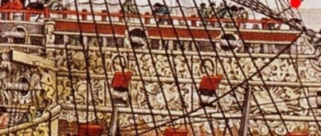
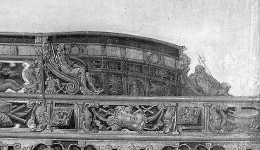
Pett and Payne, and van de Velde all show decorative panels along the bends’ tops. These panels and rails appear everywhere except along the waist. Payne shows them as red (Figure 46). There is a small rail below this panel and another one above it. Payne portrays these two rails as of the same width. Pett shows the upper rail as wider. I have followed Pett. Schematic diagrams providing their dimensions are attached.

Figure 46 Decorative Panels along the Forecastle
1730469695720.png
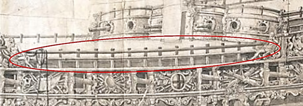
Payne and van de Velde also show railings above the decorative panels along the forecastle and half deck, and an analogous set of rails along the waist. Van de Velde’s portrayal of them along the waist is shown in Figure 47. Pett shows no railings here, but he may have considered them ancillary (which is why he does not show masts). These rails, and their dimensions, are shown in the attached schematics.

These uppermost rails are associated with the decks that have gratings over them. It would be reasonable for modelers who do not cover their decks with gratings to omit these rails, and portray only the decorative panels.


Figure 47. Van de Velde’s Portrayal of the Rails along the Waist
1730469747996.png

Scuppers​

Scuppers are holes in a ships’ side for draining water. Lead tubes that angled downwards and into them from the side of the deck. Scuppers were fitted with leather sleeves.

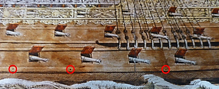
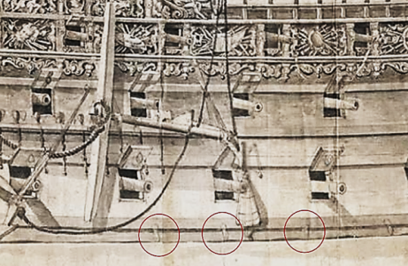
The Payne engraving shows what appear to be 7 scuppers on the Sovereign (three of them, circled in red, are shown in Figure 48) Van de Velde’s copy of the Payne engraving clearly shows them as scuppers because he shows them with their sleeves.(Figure 49) The van de Velde drawing shows them closer to the wale’s bottom than the Payne engraving. All the scuppers shown by Payne and van de Velde drain the lower gun deck.


Figure 48. Scuppers in the Payne Engraving

1730469816673.png

Figure 49. Scuppers in the van de Velde Drawing
1730469837724.png
The foremost and aftmost scuppers on Payne and van de Velde lie below the upper mail wale. The remaining scuppers in the Payne engraving all puncture it. Shipwrights were reluctant to puncture the wales, (Fox) so portraying them as doing so may be another error in the engraving. A more appropriate place for scuppers is below the upper main wale.

Doors and Windows​

Entry doors were likely present on all 3-decked ships. They are first portrayed on Pett’s Prince Royal. (L. Laughton 2006, 188)

Only van de Velde shows an entry door in the Sovereign’s hull. It is on the ship’s port side. It is not seen on the Pett painting because he shows the ship’s starboard side. Payne, who does show the port side, does not portray this door. There are only two explanations for this; either Payne made a mistake, or the door was added after the Sovereign was launched.

It is unlikely the door was added after the Sovereign’s launch. This ship was designed as an attraction. A door provides an easy way for visitors to enter the ship. The alternative is to have them board by climbing up nettings, and going over the gunwale at the waist. This required considerable exertion, especially on a 3-decker. In a later century, one sea captain who felt that his lieutenants were overweight, ordered the entry door sealed to make them climb aboard. (L. Laughton 1922, pg 188) It is unlikely that visitors, including visitors like Samuel Pepys and his lady friends, noblemen, and noblewomen wearing dresses (who would incur the immodesty that climbing an netting would entail), would be subjected to a such climb. It is more likely that Payne made a mistake.

Others seem to have regarded the Payne engraving as a near-perfect representation of the Sovereign, and have not acknowledged the possibility that this is an error. This, for example, seems to be why Sephton tells us, without evidence or explanation of how it could have been accomplished, that “we are left with the suggestion that, as the engraving is in reverse the entry port may have been on the port elevation only [italics added].” (Sephton 2011, 46) It is more likely that an omission as obvious as a missing door indicates that the engraving was prepared with less than perfect attention to detail.

I have placed the door as shown by van de Velde, just fore of the middle gun deck’s seventh port, and so that the beams for the deck above remain intact. Van de Velde shows that its width is about that of a port on the lower gun deck, 30 inches.

Payne shows several windows on the ship. Knyff also shows them. Pett does not, but he may have considered them ancillary. It seems more likely than not that the Sovereign had windows to give light to some of the darker regions of the ship’s interior. The only other way to provide light in the 17th century was to burn something, and captains and crews sought to avoid this wherever possible. They were rightfully afraid of fires on board. I have placed 24 x 20 inch double windows at the quarter deck’s aft end (these serve the upper gun deck and the half deck), and a 20 x 20 inch window (that serves the quarter deck) under the roundhouse.

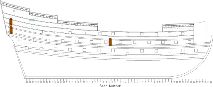
The figure below shows the reconstruction up to this point. Doors that lead to the quarter galleries are also shown. This figure does not show the upper railings along the grated weather decks.
References​

Fox, Frank. Personal Communication.

Laughton, L.G. Carr. 2006. Old Ship Figure-Heads & Sterns. Ontario, Canada: Algrove Publishing Limited.

Laughton, L.G.H. 1922. Old Ship Figure-Heads and Sterns with which are Associated galleries, Hancing-Pieces, Catheads and Divers Other Matters that Concern the 'Grace and Countenance' of Old Sailing Ships. London: Halton & Truscott Smith.


Sephton, James. 2011. The Sovereign of the Seas. Stroud: Amberly Publishing.


Upper Railings.png
 

Attachments

Have you considered that the Payne drawing is the SB side and therefore not showing the door?
The Payne image is an engraving and if the artist want to give a proper representation he has to prepare the copper plate in mirror image. If he considered PS and SB side equal he maybe decided not to draw in mirror image. This would then be the SB side and not the PS side which explains the missing door.
 
Hi Maarten;

This is unlikely, as what Charlie calls the Pett Portrait quite clearly shows that the hancing pieces to the aft of the waist are Mars with his shield and sword on the starboard side, and Neptune on the port side.

Payne's engraving has Neptune on the port side, and not Mars. If it was a reversed image, he would show Mars.

See below for Neptune and Mars.

Ratty

1730621008169.png
 
Hi Maarten,
Thanks for your comment. This seems to be what Sephton is saying, but doesn't explain. I can further elaborate on my thinking by adding to Bilge Ratt's excellent comment. There are several relevant points:

(1) If Payne considered both sides of the ship equal, he made a mistake. They aren't equal.

(2) Payne certainly knew what all engravers knew; his prints would be a mirror image. This is proved by the fact that the letters "CR" on the decoration at the quarter deck's fore end are not backwards. This means he "wrote" them as backwards on his engraving plate. It therefore seems likely that he also knew the starboard side of his prints would ultimately look like the port side. It wouldn't have been difficult for him to know there was a door on the port side. All he had to do was move around to the other side of the ship. It would have been hard to miss. Yet, he still chose not to put a door in. This is a mistake.

(3) Perhaps Payne never made the connection that the print would look like the port side, even though he knew his final print would be reversed. Not making this connection is also a mistake.

(4) The only way I can think of where it is difficult to say Payne did not make a mistake is to hold that Payne was portraying the ship with an artist's mindset, not that of a shipwright. He wanted to portray how beautiful this ship was, and particularly its ornate decorations. As such, he embellished his portrait by putting the ship at sea, and portraying crew and gentlemen on it. He had no idea that people would come along 250 years later and try to build models from his engraving. In his mind, then, lack of perfection wasn't important. Here, the fault lies not with Payne, but with us "modern" folks who read more into the engraving than he ever intended. The implication is that we should be highly skeptical of Payne's entire engraving, because it is difficult to know how many other inaccuracies it contains. In fact, we probably should be skeptical of all art from this time. This is why I have, wherever possible, tried to relate my reconstruction to contemporary written ship design works. It allows us to say that at least the reconstruction fits with what shipwrights (not artists) would have done.

Now, I going to make this reply REALLY long by exposing my mindset. I come from a background in evidence-based medicine. In this field, we attempt to rank medical studies based on how trustworthy their results are. We do this by using something called "evidence hierarchies." We need to do this because at least half (and probably closer to two-thirds) of the published medical studies are so poorly designed that they would not be allowed entry into an American 8th grade science fair. We just can't trust their results. The idea behind these hierarchies is to base conclusions about whether a drug, device or procedure works using only the best available evidence.

The same is true in historic ship reconstruction. We want to again base conclusions on the most reliable evidence, and much of the evidence we have is highly unreliable. Art is unreliable. I would put it at, or at least 17th century art, or near the bottom of the evidence hierarchy. The most reliable evidence, which is not possible for 17th century ships, would things like photographs, and shipwright's original plans.

I've mentioned this idea in a couple of forums before, and it never gains traction. Nevertheless, I still think that it would be worthwhile for the community to come up with such a hierarchy. It would help those who want their models to be as accurate as possible, and could help avoid fiascos like the widespread acceptance of at least one previously published book on the Sovereign. A hierarchy would also give folks some perspective about how trustworthy the plans are for a given ship are, and how trustworthy such plans can possibly be (in case anybody's interested, I'd rank my reconstruction somewhere near the middle of the evidence hierarchy. This looks bad, but it is a much higher rating than I'd apply to any previous plans). At the same time, I admit that developing such a hierarchy would be difficult in the extreme.
 
On another note, there is a question I've been meaning to ask.....

Does anyone know how big the spaces between timbers were on the deck gratings? My understanding is that they were rather small on hatches so sailors wouldn't get their feet caught in them. However, just the opposite might be true for gratings designed to inhibit boarding.
 
Hi Maarten,
Thanks for your comment. This seems to be what Sephton is saying, but doesn't explain. I can further elaborate on my thinking by adding to Bilge Ratt's excellent comment. There are several relevant points:

(1) If Payne considered both sides of the ship equal, he made a mistake. They aren't equal.

(2) Payne certainly knew what all engravers knew; his prints would be a mirror image. This is proved by the fact that the letters "CR" on the decoration at the quarter deck's fore end are not backwards. This means he "wrote" them as backwards on his engraving plate. It therefore seems likely that he also knew the starboard side of his prints would ultimately look like the port side. It wouldn't have been difficult for him to know there was a door on the port side. All he had to do was move around to the other side of the ship. It would have been hard to miss. Yet, he still chose not to put a door in. This is a mistake.

(3) Perhaps Payne never made the connection that the print would look like the port side, even though he knew his final print would be reversed. Not making this connection is also a mistake.

(4) The only way I can think of where it is difficult to say Payne did not make a mistake is to hold that Payne was portraying the ship with an artist's mindset, not that of a shipwright. He wanted to portray how beautiful this ship was, and particularly its ornate decorations. As such, he embellished his portrait by putting the ship at sea, and portraying crew and gentlemen on it. He had no idea that people would come along 250 years later and try to build models from his engraving. In his mind, then, lack of perfection wasn't important. Here, the fault lies not with Payne, but with us "modern" folks who read more into the engraving than he ever intended. The implication is that we should be highly skeptical of Payne's entire engraving, because it is difficult to know how many other inaccuracies it contains. In fact, we probably should be skeptical of all art from this time. This is why I have, wherever possible, tried to relate my reconstruction to contemporary written ship design works. It allows us to say that at least the reconstruction fits with what shipwrights (not artists) would have done.

Now, I going to make this reply REALLY long by exposing my mindset. I come from a background in evidence-based medicine. In this field, we attempt to rank medical studies based on how trustworthy their results are. We do this by using something called "evidence hierarchies." We need to do this because at least half (and probably closer to two-thirds) of the published medical studies are so poorly designed that they would not be allowed entry into an American 8th grade science fair. We just can't trust their results. The idea behind these hierarchies is to base conclusions about whether a drug, device or procedure works using only the best available evidence.

The same is true in historic ship reconstruction. We want to again base conclusions on the most reliable evidence, and much of the evidence we have is highly unreliable. Art is unreliable. I would put it at, or at least 17th century art, or near the bottom of the evidence hierarchy. The most reliable evidence, which is not possible for 17th century ships, would things like photographs, and shipwright's original plans.

I've mentioned this idea in a couple of forums before, and it never gains traction. Nevertheless, I still think that it would be worthwhile for the community to come up with such a hierarchy. It would help those who want their models to be as accurate as possible, and could help avoid fiascos like the widespread acceptance of at least one previously published book on the Sovereign. A hierarchy would also give folks some perspective about how trustworthy the plans are for a given ship are, and how trustworthy such plans can possibly be (in case anybody's interested, I'd rank my reconstruction somewhere near the middle of the evidence hierarchy. This looks bad, but it is a much higher rating than I'd apply to any previous plans). At the same time, I admit that developing such a hierarchy would be difficult in the extreme.
Medicine is as much art as science. Most 17th century ship model builders realize that in order to nail down each and every detail, you occasionally have multiple sources to draw from, such as those previously discussed for HMS Sovereign of the Seas. You are then faced with having to compare these sources, and rank the details within them on accuracy, applying what you've learned from conventions use on other vessels of the time/place. It's a huge, complicated puzzle with many of the pieces missing. The Sovereign stands out from other contemporary vessels in that there are fortunately several artist's pieces to draw information from, scattered across several decades, each with its own good points and bad points. Most vessels from the time have no illustrations or evidence to work from. At least the sources which depict the Sovereign are very similar, unlike those which depict Soleil Royal.
 
On another note, there is a question I've been meaning to ask.....

Does anyone know how big the spaces between timbers were on the deck gratings? My understanding is that they were rather small on hatches so sailors wouldn't get their feet caught in them. However, just the opposite might be true for gratings designed to inhibit boarding.
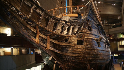
Looking at a picture of a 19th century wooden ship's grating, I measure the holes at 2.3 cm x 2.3 cm each. The grating sizes vary a bit. Take a look at some Vasa photos for a good estimate. Boarding nets and spar deck openings were larger.

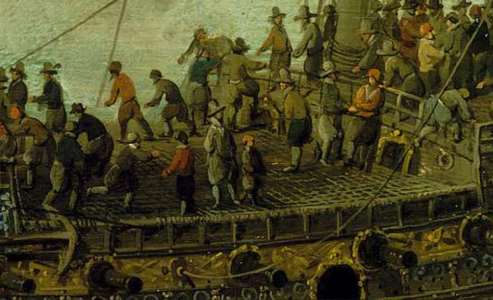
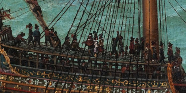
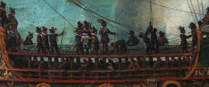
Two paintings of the HMS Prince Royal 1610 show what appears to be a mesh of ropes (net) over what probably is a spar deck. which leads me to believe the wooden weight of the spar deck is reduced to as little as possible to support the deck netting. This is far lighter than an all wood deck grating, and may have been easier to dismantle and store. The holes in the spar deck appear to be about 10 cm x 10 cm square.

1730649168462.png

More spar deck close-ups on HMS Prince Royal. Netting seems to be used over spars. Halfdeck:
1730800748946.png

Waist:
1730800819933.png

Forecastle:
1730800839791.png
 
Last edited:
Many thank for your detailed answer which opinion I certainly share with you.
From the perception of shipwright plans it would be extremely valuable if the Boston museum would ever consider to do a MA XRF scan of the drawing/painting to see if indeed this painting is based on an underlaying shipwright plan.
 
Thanks for the information about gratings, Kurt. I'm doing some thinking ahead, and trying to decide whether adding the gratings will obscure too much of the detail on the weather decks. I'd welcome any other input or photos anyone might have.
 
Maarten,
I also wish the museum would have the painting scanned. My suspicion is that the painting is not based on a true sheer plan but, rather, that the artist drew a sketch to guide his painting. The reason I suspect this is that the shape of the stem on the painting does not match Pett's stated 38 foot rake for it. The stem rake on the stem is compressed, which is what we'd expect from the perspective artists use when drawing highly curved surfaces. I found this out the hard way. I tried for weeks to get the painting's portrayal of the stem to match Pett's rake, and couldn't do it.
 
Hi Charlie;

From my readings of contemporary records, the spar deck (as they were called) was made by spanning from side to side with rafters, lightweight timbers, which were supported by pillars. I don't know if there were one, or two pillars to each rafter; I think that it is a matter of making your own choice, as it would depend upon the layout of the centre of the deck with its hatches etc. It is also possible that there was a central timber running fore and aft under the rafters, which was in turn supported by pillars. This would dramatically reduce the number of pillars required. The rail at the side upon which these rafters sat was called the rafter-rail, from which the later term 'rough-tree' rail at the side of the waist derived. Ultimately they all come from 'roof-tree'. I would expect (with no evidence at all, I must admit) that there would be one rafter to each stanchion of the rail, with the netting fixed taut over them.

One interesting point to note from Willaerts' painting of the Prince which Darius has posted above, is that the spar deck stops short of the doorway in the after bulkhead, thereby allowing the door to be used. Presumably the gun-crews below had to crouch a bit!

Spar decks were sometimes made of a combination of timber gratings and netting, but I need to dig out the reference I saw for this, and I can't remember where it was.

Ratty
 
Thanks, Ratty. That's very helpful. One question I still have is "How much detail on the decks I'll be able to see through the grating." For example, is it worth the effort to put the decorations on the guns, or will they be pretty much hidden?
 
Hi Charlie;

That would obviously be a personal decision, based on your own preferences and reasons. For what it's worth, my thoughts are that if you ask because you will build a model, and you want to be as realistic as possible, it would still depend upon the scale you use. At 1:48, I would certainly think it worthwhile to show the decoration on the guns, as it will be visible through the mesh. At 1:64 it would be desirable, but less noticeable. Alternatively, perhaps you can show half of the spar deck, along one side of the deck; or just on the fore or aft part of the deck, leaving the remainder cut away to show the deck and its guns clearly.

Ratty
 

Scuppers​

Scuppers are holes in a ships’ side for draining water. Lead tubes that angled downwards and into them from the side of the deck. Scuppers were fitted with leather sleeves.

For clarity. The scupper holes were certainly lined with lead to minimise fungal attack. But the leather reference is for flaps cut from leather that hung down like a curtain over the holes. These acted as a simple one-way valve, minimising the amount of water that could enter into the ship, while presenting only a minor obstacle to water exiting the ship.
 
Thanks for the information about gratings, Kurt. I'm doing some thinking ahead, and trying to decide whether adding the gratings will obscure too much of the detail on the weather decks. I'd welcome any other input or photos anyone might have.
Making removable gratings for the spar deck was considered, but running rigging would probably prevent it. Since my model is based on the ship at launching, making the spar decks seems imperative. I'm still wondering how it could be done, with no consideration as to what the spar deck may hide, since partial removal of the gratings may yet be an option.
 

The Sheer Plan (continued)​

The Beakhead and Knee of the Head​

Overview​

Mainwaring describes the beakhead by saying; “The Beak, or Beakhead is that part which is fastened to the stem of the ship, and is supported with a knee which is fastened into the stem, and this is called the main knee…” (Mainwaring 1922, 93) This main knee is also called the knee of the head.

The beakhead was used as a ramp that allowed attackers to board enemy ships in the early days of the galleon (Lavery, The Ship of the Line 1984, pg 47) and, before that, it was probably used as a battering ram. However, well before the Sovereign’s time, the beakhead’s primary function evolved to become a way to give the crew access to the bowsprit, the spritsail topmast, and the associated rigging.

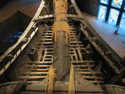
The latrine was on the beakhead. Seats of ease, which are toilets, do not appear in models until about 1670 (Simmons 1985, 99), but appeared on real ships before this. They are on the Vasa’s (1628) beakhead, where they appear at its side as small boxes (Figure 49). The beakhead was a reasonable place to put latrines because it was regularly washed by the sea. On the Sovereign though, the beakhead’s walls probably lessened this benefit.

It is unlikely that placing the latrines on the beakhead had a meaningful effect on sanitary conditions. Seamen did not always use the seats of ease, and ships were inherently foul places. Three-deckers were probably the foulest of all. The arrangement of putting one living space on top of another enhanced the downward flow of “every imaginable bit of debris, filth and human effluvia from the decks above to the bilges below.” (Simmons 1985, 15) As a result, ships were sometimes overcome with the “pestilential funks”, an odor so foul that, if it occurred, the ballast had to be thrown overboard, replaced with sand or some other suitable substance, and the inside of the hold cleaned. (Simmons 1985, 8) These conditions, combined with disease and dietary deficiencies, led to a situation in which mortality rates of 15% per year were not considered all that bad. (Fox 1980, 21).

Figure 49. Seats of Ease on the Vasa’s Beakhead

1731684243589.png
Photo from Peter Isotalo, Wikimedia Commons https://commons.wikimedia.org/wiki/File:Vasa-toilets-2.jpg Accessed Sept 13, 3022, license at https://creativecommons.org/licenses/by-sa/3.0/legalcode

The Knee’s Length​

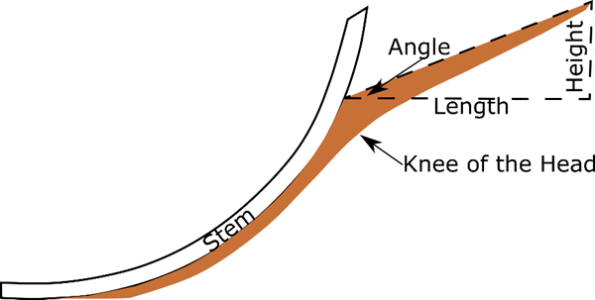
The beakhead’s length was dictated by the length of the knee of the head (this knee, and how its length was measured, are depicted in Figure 50). The length was often calculated as a proportion of the ship’s breadth. The Newton Manuscript tells us that its length should be ⅝ to ¾ the breadth, Bushnell says it should be ⅔ the breadth, and Deane computes it as ½ the breadth.

The Treatise is different in both its manner of calculating the length and how this length relates to the breadth. It tells us that the “head without the stem to the forepart of the beast [the figurehead] may be ⅕ the keel or as 10 to 11 of the galleries…”

The Pett suggest painting suggests that the length of the Sovereign’s knee, like that of the Treatise’s ship, was based on the quarter gallery’s length. It is about as long as the lower quarter gallery, including its extension. This is a little over 14 bends, (i.e., a little over 35 feet), which is a little more than ¾ of the ship’s breadth. This is much longer than in later ships.

Long beakheads, like that on the Sovereign, were a known problem. A 1671 treatise by the Dutch shipwright, Nicholaes Witsen, explains that” When all too heavy and long Beakheads break down at sea, it is often necessary to saw them off because they cannot be repaired because of their size and risk damaging the ship if left hanging loose and dangling.” (Hoving and Wildeman 2012, 123)


Figure 50. The Knee of the Head
1731684333955.png
Note: The figure shows a generic knee of the head and associated structures. The figure is adapted from Deane.

The Knee’s Angle
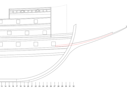
Shipwrights often thought about the knee’s angle in terms of its “steeve,” which is how many feet per some length that the knee deviated from horizontal. Bushnell only tells us to “steeve it [the knee] to Content” but that “for the steeving of him, and rounding the Knee, a Regard must be had to the lying of the Bolt-sprit [bowsprit], leaving room enough for the Lion and Scrowl under the Bolt-sprit.” The Newton Manuscript’s author is more specific, though he speaks in terms of rake, which is how far from vertical a mast is. He thus tells us “The knee of the head must not rake “more than 4 foot in length of 12 foot nor less than 3 foot thereof.” These three and four foot rises lead to angles of 14.03° and 18.43°, respectively. The Treatise is unique in speaking of angles. It only allows angles for the bowsprit that are between 12° and 13°. The steeving on Deane’s ship is ⅔ the knee’s length, which works out to 33.69°. This reflects the knee’s increasing angle during the 17th century.

Even though Deane uses a greater angle, his beakhead is relatively low for its time. This may have been because he wanted to position it so that the ship’s guns could fire over it. If so, this is a throwback to earlier beakheads. By Deane’s time, the advent of the line battle made this thinking obsolete, (Lavery, Deane's System 1670, 26) and beakheads were steeper.

I have used the Treatise’s minimum angle of 12° so most of the Sovereign’s figurehead is below the guns that protrude through the beakhead bulkhead on the upper gun deck. It also follows the pattern of ships from about 1540 to 1640, whose beakheads were horizontal, or nearly horizontal. (L. Laughton 2006, 59-60).This is subjective. Others might prefer an angle as much as the Newton Manuscript’s 18 .


The Beakhead’s Shape​

The beakhead’s shape in cross-section changed over time. It transitioned from a structure that was flat at the bottom in about 1580 to one that was V-shaped in about 1650 (Figure 51). Although these are idealized shapes, there is evidence that the shape from 1600 applies to s the Sovereign.

Figure 51. The Beakhead’s Changing Shape
1731684417731.png
Note: The figure shows cross-sections of the beakhead at three different times. The is figure adapted from Laughton. (L. Laughton 1922, 106)

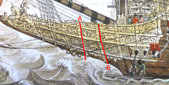
This evidence comes from the way the vertical gilded timbers are shown in Pett painting and the Payne engraving. I will discuss only the Payne engraving because the effect is more visible on it. If the beakhead’s walls were like those shown in the drawings for the beakheads of 1580 or 1650, (Figure 51), the timbers would also be drawn as a straight line from top to bottom. Line “A” in Figure 52 shows that a straight line does not conform to the timbers’ shapes. Rather, each timber is described by two straight lines (line “B” in Figure 52) joined together at an angle. This is consistent with shape like that of 1600.

Figure 52 The Beakhead’s Shape in the Payne Engraving
1731684471022.png
With this in mind, we can draw a cross section of the Sovereign’s beakhead. This is shown in Figure 53.

Figure 53 Schematic Cross Section of the Sovereign’s Beakhead
1731684514635.png

The Beakhead’s Deck​

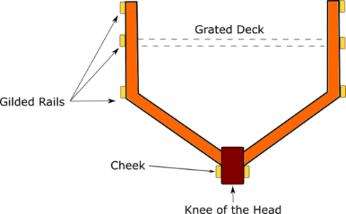
A grated deck ran along the beakhead. It was grated so the sea water that washed over the beakhead could drain. There is no direct evidence about the beakhead’s deck on the Sovereign. I have placed so that it runs along the beakhead railing that is second from the top until it reaches the figurehead. This is like Payne. Figure 53 shows this in cross section, and Figure 54 shows it in profile view.

Figure 54. The Beakhead’s Deck

1731684590070.png

The Cheeks​

Towards the end of the 1500’s, shipwrights came to understand that beakheads could be made more stable if they were supported. This led to the introduction of cheeks, which Mainwaring defines as “The knees which fasten the beakhead to the bow of the ship.” (Mainwaring 1922, 125)

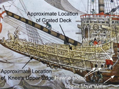
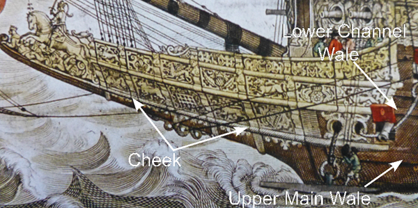
When cheeks were first introduced, they either formed part of the head itself, or were hidden under the rails. Initially, ships carried only one cheek. (L. Laughton 2006, 60) A second one was added by some time around 1600. The Newton Manuscript, which is from about this year, notes the existence of two cheeks when it tells us “The halse [hawse] must ever be placed betwixt the two cheeks of the head.” Use of this second cheek did not immediately become universal. (L. Laughton 2006, 60) The Sovereign as designed and launched had only one cheek. (L. Laughton 2006, 60) Its position is depicted in profile view Figure 55, and in cross section in Figure 53.


Figure 55 The Sovereign’s Cheeks
1731684635951.png
As implied by Figure 55 and Figure 54, the position of the Sovereign’s cheeks gives us the position of the knee’s upper edge. It is similar to that described by Bushnell, who tells us that “The Place of the Knee will be at, or very near, the upper Wail…”

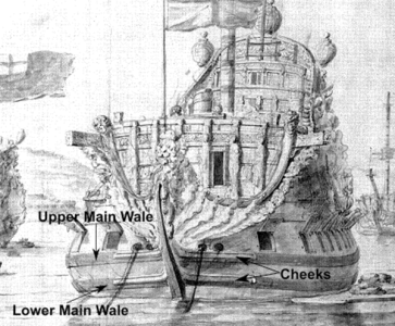
A second cheek appears to have been added to the Sovereign later in its career. This is suggested by a 1685 van de Velde drawing of the Sovereign Velde (Figure 56). The upper cheek lies on the upper main wale, and is above the hawse holes, while the lower one is on the lower main wale and is above the hawse holes.


Figure 56 van de Velde’s Portrayal of the Sovereign’s Bow in 1685
1731684682434.png

Note: Van de Velde’s drawing also shows that the knee of the head tapered, so its fore end was narrower than the end that met the ship’s hull. This was common practice. Source: Boijman’s Museum, Rotterdam

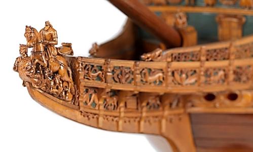
It is instructive to examine the way the Sovereign’s beakhead is portrayed on some models. Seppings’ model (Figure 57) is an example. The bottom of his beakhead becomes flat well above the cheeks shown in Figure 55. To be sure, 17th century beakheads were built this way. The Vasa’s beakhead (Figure 58) is an example. However, the portrayals by Pett and Payne suggest the Sovereign’s beakhead was different.


Figure 57. The Sovereign’s Beakhead on Seppings’ Model
1731684725284.png
Note: Photo from Royal Museums Greenwich

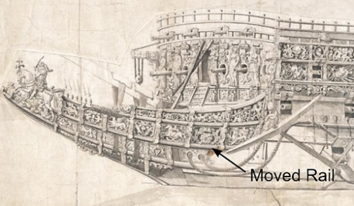
The shape Seppings gives his beakhead is like that shown in van de Velde’s drawing (Figure 59). By this time, however, there had already been a proposal for the Sovereign’s “head to bee made shorter” (see “The van de Velde Drawing and the Sovereign’s Repairs” for discussion), and van de Velde’s portrayal could indicate that the beakhead’s shape was changed when it was shortened. The van de Velde drawing also suggests an additional change. The rail that is second from the bottom on the beakhead is at the lower channel wale and above the lower gun deck’s bow chase port in the Pett painting and the Payne engraving (Figure 52), but is below this wale and just above the port’s center in van de Velde’s drawing (Figure 59).This makes it possible that the rail may was been moved to make room for a second cheek that had now been added. This cheek would, like the one shown on the Vasa and in van de Velde’s drawing of the Sovereign in 1865, have been attached to the upper main wale but, unlike these portrayals, it would be is hidden by the beakhead’s walls. This, however, is speculative.

Figure 58. The Vasa’s Beakhead
1731684787456.png
Note: Photo from Javier Kohen, Wikimedia Commons https://commons.wikimedia.org/wiki/File:The_Vasa_from_the_Bow.jpg Accessed Sept 15, 3022, license at https://creativecommons.org/licenses/by-sa/3.0/legalcode

Figure 59. Moved Beakhead Rail Shown by van de Velde
1731684838038.png

The Beakhead Bulkhead​

The beakhead bulkhead lies at the forecastle’s fore end. The Sovereign’s beakhead bulkhead was rounded. This is shown in both the Pett painting and the Payne engraving (cf. Figure 52). Van de Velde’s drawing (Figure 22) of the bulkhead may show less rounding and this, along with the fact that most ships the Sovereign’s time were built with relatively a flat beakhead bulkhead, appears to have influenced many models of the Sovereign. As mentioned before, though, the Sovereign had changed by the time van de Velde saw the ship. These changes could have included changes in the beakhead bulkhead’s shape. An additional gun port also appears to have been added to the beakhead bulkhead. Van de Velde shows six gun ports in it, while Pett and Payne show only four.

Rounding the beakhead bulkhead was relatively common practice in England at the end of the 16th, and the beginning of the 17th century. Phineas Pett’s Prince Royal had such a beakhead (L. Laughton 2006, 49). A rounded beakhead creates more space at the fore end of the forecastle’s deck. This space alleviates a problem seen in some models of the Sovereign. In them, the foremast lies very near the fore forecastle railing, leaving little or no room for the deck ‘s openings to the topsail sheet bitts, which should lie in front of the foremast.

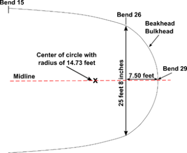
As previously discussed, the amount the bulkhead rounds on the present plans is based on the Treatise. Figure 60 shows the top view of the bulkhead’s shape, and its position with respect to the forecastle. The bulkhead is drawn as part of a circle that has a 14.73-foot radius. It arcs 7½ feet (3 bends) forward from the forecastle’s sides at the side of the ship at bend 26.


Figure 60. The Beakhead Bulkhead’s Shape
1731684880678.png
Note: Bend 15 is the forecastle’s aft end, and bend 26 is its fore end at the ship’s side. The forecastle’s width will be discussed later.

References​

Fox, Frank. 1980. Great Ships. London: Conway Maritime Press.

Hoving, A.J., and Diederick Wildeman. 2012. Nicolaes Witsen and Shipbuilding in the Dutch Golden Age. College Station, Tx: Texas A&M.

Laughton, L.G. Carr. 2006. Old Ship Figure-Heads & Sterns. Ontario, Canada: Algrove Publishing Limited.

Laughton, L.G.H. 1922. Old Ship Figure-Heads and Sterns with which are Associated galleries, Hancing-Pieces, Catheads and Divers Other Matters that Concern the 'Grace and Countenance' of Old Sailing Ships. London: Halton & Truscott Smith.

Lavery, Brian. 1670. "Deane's System." In Deane's Doctrine of Naval Architecture, 1670, by Anthony Deane, 128. Annapolis, MD: Naval Institute Press.

—. 1984. The Ship of the Line. Vols. Volume II: Design, Construction and FIttings. Londin: Conway Maritime Press.

Mainwaring, Henry. 1922. The Life and Works of Sir Henry Manwaring. Edited by G.E Manwaring and W.G. Perrin. Vol. 2. 2 vols. London: THe Navy Records Society.

Simmons, Joe John. 1985. The Development of External Sanitary Facilities Aboard Ships of the FIfteenth to Nineteenth Centuries (Thesis). College Station, TX: Texas A&M University.
 
Back
Top