17th Century Ship Design and the Sovereign of the Seas (1637)

Aha! So you're the one that's interested. I have the feeling that all of this documentation is putting everyone else to sleep, but I thank you very much.
Hi Charly,

Certainly not, love your research. Can see you spend 10 years researching her.
I just started and learn a lot to hopefully start my build in 5 years from now.
SotS is a tough cookie especially as there is so much contradictional information on her.
 
CHARLIE T MANY, MANY ARE INTERESWTED IN THISW DISCUSSION, I DO NOT COMUNICATE AS MY KNOWLOEDGE IS LIMITED BUT BOY AM I LEARNING ONE OF THE FEW TOPICS OF INTEREST ON SOS, KEEP IT UP. GOD BLESS STAY SAFE ALL DON
 
Section IV: The Sheer Plan (continued)

The Decks (continued)​

The Middle Gun Deck’s Course​

Shipwrights determined the height of the middle gun deck using the lowest gun deck as a reference. Pett tells us that the plank-to-plank height between the lower and middle gun decks was 7 feet. This means that there were 7 feet between the top of the lower gun deck’s planking and the bottom of the middle gun deck’s planking. Specifications like this frequently referred to only the deck’s height at the midship bend. Often, the middle gun deck’s aft end was placed higher. The increased height at the stern caused by rotating the deck in this way made more room for the tiller. One method shipwrights used to achieve this increased height on their plans was to rotate their bows, which made the deck’s fore end lower. (Fox)

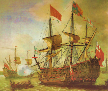
Phineas Pett apparently saw no need to increase the deck’s height aft. Peter Pett’s painting shows that the Sovereign’s the middle deck’s ports are the same distance above the lower gun deck’s ports along the ship’s entire length. Hence, the middle gun deck did not rise aftwards. It also does not become lower forward. Accordingly, the middle gun deck is parallel to the lower gun deck on the present plans.


The Upper Gun Deck’s Course​

The upper gun deck’s height was determined using the middle gun deck as a reference. Pett tells us that the plank-to-plank height between the middle and upper gun decks was 7 feet 3 inches. As with the middle gun deck, this often referred to only the deck’s height at the midship bend.

The upper gun deck’s aft end, like that on the middle deck, was often higher than its fore end. This was done to create headroom in the cabins below, and the increase could be obtained by again rotating the bow used to draw the deck. We cannot ascertain the middle gun deck’s entire course from any artistic representation of the Sovereign because there are no gun ports along its upper quarter gallery. However, all the upper gun deck ports we can see in the Pett painting are the same distance above the middle gun deck’s ports. This suggests that the Sovereign’s upper gun deck was parallel to its middle gun deck. This is reflected in the current plans.


References​

Fox, Frank. "Personal Communication."
 

Section IV: The Sheer Plan (Continued)

The Decks (continued)​

The Upper Decks​

When we turn to the Sovereign’s remaining decks, we must not only ask how high they were, but also where they started and stopped. This requires us to find the weather deck’s lengths. They are called “weather decks” because there is no covering over them. They consist of the forecastle, waist, much of the half and quarter decks, and the roundhouse.

The Weather Decks’ Lengths​

Finding the lengths of most of the Sovereign’s weather decks is simply a matter of counting the number of bends along them, as shown by the Pett painting. The exception is the waist, where Pett does not portray the individual bends. Nevertheless, his painting can still be used to determine the waist’s length.

This was done two ways. First, one of the upper decks was used as a measuring stick. For example, the waist’s length equals the length of the half deck (14 bends) plus an additional 9 half deck bends. This tells us that the waist is 23 bends long. The second way was to consider the space required for the lower gun deck ports that lie under the waist.[1] The Pett painting shows that there are five such ports plus about 2 bends. Five lower gun deck ports occupy 53 feet 4 inches (the spacing of the gun ports is discussed in a later section) which is 21.33 bends. Adding in two more bends gives us 23.33 bends, which we round to the nearest integer, 23.

Having arrived at the number of bends along the waist, we can now list the weather deck lengths. This is presented in Table 6.


Table 6. Number of Weather Deck Bends Suggested by the Pett Painting
1726324548892.png
Note: *Refers to the bends along the ship’s side, and does not include the timbers along the fore side of the beakhead bulkhead.​

Now that we have found the weather decks’ lengths, there remains the task of finding the bends at which they begin and end. This consists of sliding all 68 bends of the weather decks fore and aft until we arrive at reasonable results. This is best conceived of by thinking of all the bends as attached. As we pull the forecastle’s foremost bend forward, we pull all the other bends with it. This moves the taffrail forwards. On the other hand, as we push the foremost bend aft, we also push all the other bends aft, so the taffrail is moved aft. This “attachment” simplifies our task; when we have correctly located the forecastle’s foremost bend,[2] we have automatically located all of the other bends.

A properly positioned foremost bend will meet four requirements. First, the lower gun deck’s foremost port will be no closer to the stem than 7 feet 4 inches (the reason for this will be discussed when we discuss the gun port’s spacing). Second, the beakhead bulkhead will curve in the manner shown on the Pett painting. Third, a properly positioned forecastle will lead to a reasonable rake of the upper stern and, fourth, it will also lead to a reasonable counter. Placing the forecastle's fore end at bend 26 satisfies all three requirements. This results in the weather deck positions shown in Table 7.


Table 7. The Ends of the Weather Decks
1726324685175.png
Notes: *Refers to only the bends along the ship’s side. Does not include the bends along the arcing beakhead bulkhead.
**Negative numbers denote bends aft of the midship bend.


[1] We cannot use the space required for the upper gun deck’s ports along the waist. As we will later see, the space between them is not equal.
[2] In referring to the forecastle’s foremost bend, I am referring it its foremost bend at the ship’s side. This does not include the bends along the beakhead bulkhead.
 
Section IV: The Sheer Plan (Continued)

The Decks (continued)​

The Forecastle​

The Treatise tells us that the forecastle is “the uppermost part of the foreships directly over the chase and constrained between the bulkhead thereof and the stem.” As noted in the preceding subsection, the aft end of the Sovereign’s forecastle’s lies 15 bends fore of the midship bend. From here, it extends 11 bends forward to meet the beakhead bulkhead 26 bends fore of the midship bend. The forecastle’s foremost limit is defined by an arc that is, in turn, defined by the shape of the beakhead bulkhead. Fully discussing the beakhead bulkhead is a complex topic that will be discussed more fully in a later section. For now, suffice it to say that the Treatise tells us that the forecastle “must be cut off at the 3rd timber forward on, for the more conveniency of placing the bowsprit and fashioning the head.” The current plans mimic this by placing the foremost end of the curving beakhead bulkhead at bend 29, which is three bends less than the number of forward bends on the Sovereign.

According to the Treatise, the lengths of the forecastle’s deck is to be ⅔ of the stem’s inner rake. This would be about 25 feet 3 inches long on the Sovereign. The Sovereign’s forecastle is 27.5 feet long from its aft end to where the beakhead bulkhead begins, and 35 feet long from its aft end to its foremost point at the beakhead bulkhead.

The forecastle’s deck parallels the upper gun deck. Pett implies this when he tells us that “the third deck” was 7 feet 3 inches (plank-to-plank) above the upper gun deck.


The Half Deck​

Kits for models of the Sovereign usually do not model the part of the half deck that cannot be seen from the ship’s outside, and previous attempts to reconstruct the Sovereign have not discussed this deck in detail. More attention to this deck is warranted because there are substantial differences between the way it is portrayed by the Pett painting and by the Payne engraving.

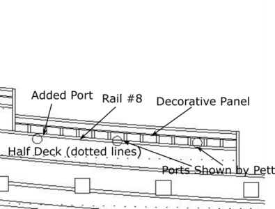
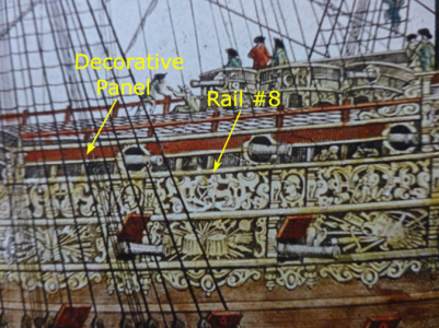
Let us first consider the way the half deck is portrayed in the Pett painting. The painting shows only two of the three ports that were actually along this deck because the aftmost port was added to the Sovereign after the painting was finished. Pett shows that the foremost port slightly cuts into a rail labelled as Rail #8 in Figure 30, and that the middle port is bisected by it. We can infer the aftmost port’s height by drawing a straight line that runs just under these two ports. This reveals that nearly all of the third port lies under Rail #8. Since the half deck must run somewhat below this line, the result tells us that the half deck is not following the run of the planking on the ship’s sides (i.e., the planksheer).


Figure 30. Pett’s Portrayal of the Half Deck’s Gun Ports
1727969899008.png
Note: Because I cannot show cropped, annotated versions of the Pett painting, I have instead provided a sketch. You can replicate the sketch on a downloaded version of the painting.

Payne’s engraving implies an entirely different half deck. One difference between it and the Pett painting is that the former shows the third port on the half deck (Figure 31). A more important difference is that the ports have been moved up, so they are now above Rail #8. This implies that Payne’s deck is higher than Pett’s. Also, because the ports run along the rail, the Payne engraving implies that the half deck follows the planksheer.

Figure 31. Payne’s Portrayal of the Half Deck’s Gun Ports

1727969934763.png

The differences between Pett’s painting and Payne’s engraving raise questions about where to place the half deck, and where to position its guns. It seems to me, at least, that it is sufficient to point out that the ship’s builder knew his own ship better than Payne knew it, and end the discussion here. However, because the differences between Pett and Payne lead to such substantially different reconstructions, and because Payne’s portrayal seems to have been used in every previous model of the Sovereign (or, at least, every model of it that I have seen), further examination of the Payne engraving is warranted.

One difference between Payne’s and Pett portrayals is that is that Payne’s gun ports are larger. Payne’s ports reach from rail #8 to nearly the top of the red, decorative panel that runs along the half deck. Pett’s foremost half deck port, shows that his ports reach only from rail #8 to the bottom of the decorative panel. All of Payne’s ports along the upper decks are large, and this hints at a possible problem with his portrayal of all of them.

A more substantial difficulty with Payne’s portrayal appears when we compare the number of half deck bends he shows to those shown by Pett. Pett portrays his deck as 14 bends long. Payne, on the other hand shows it as no more than 13 bends long. In characterizing his deck as “no more” than 13 bends long, I am assuming that there is a bend that lies just aft of the aftmost port on his deck, but just before the break at the quarterdeck. This bend is not visible on the engraving and, if Payne actually did mean to imply that a bend was here, it is obscured due to artistic perspective. The result is that this putative bend is so close to the bulkhead at the quarter deck’s fore end that one can plausibly argue that the engraving only shows 12 bends. Regardless, either Payne’s deck is at least 2 ½ feet shorter than Pett’s, or Payne has failed to draw one or two bends. The latter is most likely because the ports on the three gun decks will not correctly align with the breaks in the upper decks if the half deck has fewer bends than Pett shows. Regardless, Payne’s portrayal of the half deck is not done as carefully as we would like
.

A third difficulty with Payne’s portrayal of the half deck is that this deck’s aftmost guns are precariously close to the bulkhead at the quarter deck’s fore end. If we take Payne’s portrayal literally, as many modelers have done, the aft side of his port is less than half the gun port’s width from it so, it is only about seven or eight inches from the bulkhead. Putting a port this close to a bulkhead means that it is difficult to aim the gun straight. This puts the bulkhead in jeopardy when the gun is fired and recoils. Although Pett does not show this port, equal spacing of his half deck ports places the aft side of the aftmost port a little over 2 ½ feet from the bulkhead at the quarterdeck’s fore end. This is a more reasonable distance from the bulkhead, and it again suggests that something is wrong with Payne’s portrayal.

Another difference between Payne and Pett is that the former puts the half deck’s foremost gun port just aft of the half deck’s third bend. It is just aft of the second bend in Pett’s portrayal. The result is that Payne’s placement puts the foremost port only three bends fore of the middle port, whereas Pett’s port is four bends away from it. Payne’s portrayal thus concentrates the guns’ weight more than Pett’s does. Pett’sFigure 30 portrayal is more satisfying because shipwrights sought to distribute the weight of the guns. This put less strain on the deck beams.

Yet a fifth difference between Payne and Pett is that the latter shows the middle gun port (which is the aftmost gun port on the Pett painting) as bisected by rail 8, whereas Payne shows the port as lying above the rail. Since the port must stay at a constant distance above the deck, Pett’s drawing is forcing the half deck down, whereas Payne’s engraving is pulling it up. Payne’s placement of this port assures us that his half deck follows the planksheer, and Pett’s portrayal tells us that it does not.

That Payne’s engraving suggests the half deck follows the planksheer is significant. This is contrary to common contemporary building practice. For example, the book “Great Ships” (Fox 1980) presents depictions of about 40 17th century ships. Two of the portrayals are ambiguous, but every one of the remaining ships with guns along its upper decks shows that these ports cut into the ship’s sides and, therefore, that the upper decks that do not follow the planksheer. Deane’s drawings also show that the upper decks do not follow the planksheer. It was thus uncommon for any of the aft upper decks to follow the planksheer.

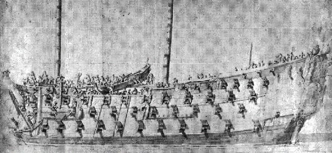
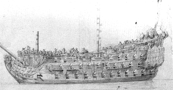
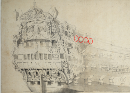
It is clear that that upper decks of the repaired versions of the Sovereign did not follow the planksheer. One example of this is van de Velde’s sketch of its starboard side previously shown in the section that discusses his drawing. Another example is his drawing of the Sovereign’s port side, which is shown in Figure 32. It is also shown in a third drawing by van de Velde, (Figure 33) which Henrik Bussman says is the Sovereign in about 1663 (Busmann 2002, 52), and a fourth one that is from about 1685 (Figure 34).


Figure 32. Van De Velde’s 1673 Sketch of the Sovereign (Port Side)
1727970038337.png

Note: The half deck’s length had been modified by the time of this sketch.

Figure 33 Van de Velde’s Drawing of the Sovereign from 1663(?)
1727970084625.png

Note: In This is an unusual drawing, so I have provided extended comments about it. If the drawing is, indeed, from any date after 1660, it should not show the aftmost port that was initially on the middle gun deck. This port was removed during the 1659-1660 repair. Van de Velde not only shows it, he places in rather high. He puts most, if not all, of this port as lying above the lower edge of the lower channel wale. This is unlike his most famous portrayal of the Sovereign, unlike Payne’s engraving, and unlike the Pett painting, all of which show most of the port below the lower channel wale. The two ports fore of this one also appear higher than in other portrayals. The relatively high placement of these ports suggests the deck had been raised by the time of this drawing, which is consistent with the changes made during the 1659-1660 repair.

Van de Velde also portrays the port next to the middle gun deck’s aftmost port as lying under the quarter galleries instead of being where the now-removed quarter gallery extensions were. This is incorrect. He shows this and the aftmost port as arched, and the latter port as cutting into the lower quarter gallery. No other depiction of this port shows these latter two features.

I have no convincing explanation for this drawing. That van de Velde shows the aftmost port raises the possibility that he was not attempting to show the Sovereign as it actually was. He may have been attempting to see how the now-removed port would fit on the ship that was before him. This, however, does not explain why he shows the port next to the aftmost port as being under the quarter gallery. On the other hand, the drawing appears unfinished. The outlines of several ports along the fore half of the lower gun deck are present, and this gives the impression that van de Velde was still working on where to place them, or that he had placed them to his satisfaction, but had not yet erased where he originally drew them. If nothing else, the drawing highlights the difficulties of using 17th century artwork to make definitive statements about the Sovereign, even if that artwork is by an accomplished maritime artist.

Figure 34. Van de Velde’s 1685 Drawing of the Sovereign
1727970138254.png

Note: The ports along the upper decks are difficult to see in this drawing, so I have circled them in red.

These drawing are important because they make it difficult to argue that the Pett painting shows the Sovereign’s half deck was planned one way, but that Payne shows it was built another way. If this were the case, the four drawings shown above would show yet a third change in the half deck’s placement. This is an unusually mobile half deck for a ship that began with flush decks. Another way of thinking about such a deck is that decks probably did not commonly run with the planksheer because shipwrights of the Sovereign’s time found this arrangement more satisfactory than decks that did run with it. If this is the case, then the Sovereign was originally designed in a manner that shipwrights would have found satisfactory to one they later considered less satisfactory, so it was changed back to a “satisfactory” deck. This seems to me to be a difficult position to hold.

Payne’s portrayal of the half deck as following the planksheer has downstream consequences. If the deck is allowed to continue along this trajectory to the stern, it is impossible to correctly align the upper and lower windows on the stern because the half deck is more than eight feet too high. This trajectory also makes it impossible to correctly position the upper quarter gallery. This is because there was a door on the half deck’s aft end that led to this gallery (just as there is a door upper gun deck’s aft end that led to the lower quarter gallery; the galleries will be discussed in a later section), and we need to raise the upper quarter gallery’s aft end by more than eight feet to meet this door. Since the lower quarter gallery also meets its own door, the result is that upper and lower quarter galleries that are not parallel to each other[1], which is contrary to all contemporary depictions of the Sovereign.

The only way to line up the stern windows, and make the two quarter galleries parallels is to put a fall in the deck to bring its aft end down to an appropriate level (this is seen on plans by John McKay, who has put two small “falls” in his half deck). This seems contrary to Pett’s intentions. He tells us that “the third deck” is 7 feet 3 inches above the upper gun deck. If the “third deck” referred only to the forecastle, Pett could have easily said so. He did not. If, on the other hand, we take the term “third deck” to refer to not only the forecastle, but also the half deck, there is no need to put a fall in the deck. When the entire half deck is 7 feet 3 inches above the upper gun deck, the stern gallery windows align with each other, the quarter galleries are parallel, and both align with everything else just as they should.

Making the entire half deck is 7 feet 3 inches above the quarterdeck makes it parallel to the upper gun deck. On the face of it, this appears unusual. It is thought that it was customary to elevate the half deck’s aft end to create more headroom in the cabins below. One can question, though, whether this was customary in the early 17th century, or whether anything on what was only England’s second three-decked ship can be said to be customary. More importantly, though, is that the lack of increased headroom is not solely dictated by the height of the half deck’s aft end. It is also dictated by the need to correctly align the upper and lower stern gallery windows with each other, and to make the two quarter galleries parallel to each other. If we attempt to create the “customary” increase it headroom, we must misalign these parts of the Sovereign. Accordingly, the “customary” aft increase in headroom could not have been present on this ship.

The discrepancies between Pett’s painting and Payne’s engraving leave us with four alternatives:

  • The first is that original design of the Sovereign’s half deck, as portrayed in the Pett painting, was changed just before the ship was built, so that it now looked like the Payne engraving. However, Pett would have no reason to do this, particularly since the change yielded a ship not built according to common practice. Furthermore, no records have been located to suggest that a change was made.
  • Second, we can hold that the Sovereign’s half deck was changed in response to the King’s addition of guns to the Sovereign. The difficulty here is that there is no good reason to rip out an existing deck and replace it with a different one when the original deck could also carry the added guns. Also, no records have been located to support this assertion.
  • The third alternative is that the Pett painting is correct, so Payne’s engraving is not.
  • The fourth alternative is the converse of the third, that Payne is correct and Pett is not. Choosing this latter alternative requires us to make several assumptions that are worth delineating.
In delineating these assumptions, bear in mind that when we decide not use the Pett painting, we are making all of them. Failure to believe any one of them calls Payne’s portrayal into question The assumptions we must make are:

  • The ship’s builder has inaccurately located the half deck’s foremost port.
  • The ship’s builder put the aftmost port on his painting (which later becomes the middle gun port) at the wrong height.
  • The height that Phineas Pett gives for the half deck above the upper gun deck is either wrong, or does not apply to the half deck. In making this assumption we must also ignore the fact that Phineas Pett’s given half deck height places the two ports shown on the Pett painting and the third port implied by this painting just as the painting shows.
  • The Sovereign’s half deck did not follow common building practices.
Making these assumptions means that we are assuming that part of what the ship’s designer tells us about his ship is irrelevant or wrong, and what the builder shows us about his half deck is also wrong. It is difficult to dismiss both the information provided by the ship’s designer and its builder. Doing so requires proof that extends beyond existing artistic portrayals of the Sovereign. Stated in another way, a decision to place the half deck as shown by Peter Pett is based both on artwork (Peter’s painting) and historical records (Phineas’ list of dimensions). A decision to position the half deck as Payne portrays is based only on contemporary artwork which, as discussed in the section “Which Artwork Should We Use?”, is not always reliable. A decision to use the Payne engraving needs to also be supported by historical records to be on an even footing with the Petts’ placement of the deck.

Based on all of the preceding considerations, the conclusion here is that the half deck’s gun ports on the Sovereign were positioned as shown in Figure 30, and that the half deck did not run with the planksheer. To put it plainly, the Payne engraving is incorrect. The correct half deck follows the pattern of the middle and upper gun decks; it is not raised to create headroom aft, even though it often was in later ships. The Sovereign’s design was thus, simpler than that of later ships, which is a theme I will return to.

A number of reasons for Payne’s error can be suggested, but none can be proven. For example, Payne was obviously aware that the King had added guns to the Sovereign (after all, he portrays the added guns), but the aftmost one may not have been installed at the time of his engraving. As a result, Payne guessed where it would go and aligned the other ports with it. Not being a maritime artist, he guessed wrong. Alternatively, Payne probably engraved his plates from a sketch he made at dockside. His sketch may have been wrong or unclear.


References​

Busmann, Hendrik. 2002. Sovereign of the Seas. Hamburg, Germany: Deutches Schiffahrtsmuseum, Bremerhaven, und Convent Verlag, Hamburg.

Fox, Frank. 1980. Great Ships. London: Conway Maritime Press.


[1] We implicitly set the position of the lower quarter gallery when we positioned the middle and upper gun decks.
 
Section IV: The Sheer Plan (Continued)

The Decks (continued)​

The Quarterdeck​

Positioning the Sovereign’s quarter deck is a matter of speculation. Pett does not give us any dimensions it.

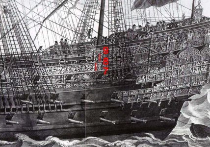
As with the half deck, there are differences between Pett and Payne that are relevant to the quarter deck. Payne’s upper railings are drawn differently than Pett’s. This is shown in Figure 35. Here, the rail above rail #8 is labelled as rail #9, and the rail below rail #8 is labelled as rail #7. The Pett painting shows that the space between rails #7 and #8 is the same as the space between rails #8 and #9. Payne, on the other hand, shows that the space between rail #8 and rail #9 is greater than the space between rail #7 and rail #8. This raises the possibility that Payne’s quarterdeck is further above his half deck than shown by the Pett painting. At the very least, the way Payne has drawn the relevant rails is problematic. There is no reason why the separation between rails should have been changed between the time of the Sovereign’s design and when it was built. This suggests another error in the Payne engraving. There is also no reason the quarter deck’s height should have changed.

Payne also shows the deck’s single port in a different position than the Pett painting. Payne places it in the middle of the deck, Pett places it further forward.


Figure 35 Payne’s Half and Quarter Deck Rails

1728138720054.png

Note: The two red vertical lines in the figure are of equal length. The lowest line is drawn from the top rail #7 to the bottom of rail #8. The upper line begins at the top of rail #8, and does not reach the bottom of rail #9. This shows that the space between rails #8 and #9 is greater than the space between rails #7 and #8.

On the assumption that the Sovereign’s design was relatively simple, I have placed the quarter deck seven feet (plank-to-plank) above the half deck. In later ship’s at least, the quarter deck rose further above the half deck as it moved aft. Keltridge would have this deck rise from 6 feet above the half deck to 7 feet above it at the stern. There is no need for such a rise on the current plans because the quarter deck is already seven feet above the half deck at its aft end.

I have positioned the port as shown by Pett because it is reasonable to follow the builder’s portrayal. Given the difficulties with Payne’s portrayal of the half deck’s gun ports, his placement of the quarter deck’s gun port may be another error in his engraving.


The Roundhouse​

As with the quarter deck, positioning the roundhouse is a matter of speculation. I have placed its fore end 5 feet 5 inches above the quarter deck (plank-to-plank), and its aft end about 8 feet 1 inch above it. The height of the deck’s fore end allows 5 feet of headroom (after considering the thickness of the roundhouse’s deck beams) for someone entering the door in the inboard bulkhead at this deck.

The Topgallant Poop​

The aft end of the roundhouse in ships of this era often had a 2-3 feet high box-like structure on it called the poop. The poop was sometimes replaced in very large vessels with an upper roundhouse covered by a short deck called the topgallant poop or royal poop deck. This is where the ship’s trumpeters slept. (Fox 1980, pg. 16). Payne was aware that this structure had something to do with trumpeters because he shows them on it, even though they were not there when he saw the Sovereign.

Payne is the only contemporary source that portrays the topgallant poop. His portrayal is consistent with the idea that the topgallant poop was small, so I have made it 3 feet high and extended it 5 feet (2 bends) from the taffrail.

References​

Fox, Frank. 1980. Great Ships. London: Conway Maritime Press.
 

The Decks (continued)​

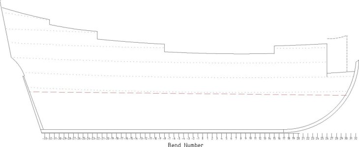
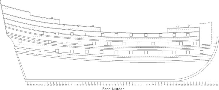
Now that the discussion of the decks is finished, it is appropriate to show the plans for the Sovereign drawn so far. They appear in the figure below. The decks are show by the dotted lines, which denote the heights of the planked deck tops at the side of the ship. The topgallant poop and beakhead bulkhead are shown by dashed lines. More details about the beakhead bulkhead will be provided in a later section. Details about the dimensions of the counter and the heights of the bends’ tops will also be discussed in a later section.

The midship bend is labelled as bend 0. Bends aft of it are denoted by negative numbers. Bends are 30 inches apart.

The attached file gives the heights of every deck, expressed in feet from the keel’s top, at every bend.

1728142577046.png
 

Attachments

Last edited:
The Sheer Plan (continued)

Gun Ports​

Port Heights above the Deck​

Pett does not tell us how far the Sovereign’s ports were above its decks, and it is difficult to directly take information from contemporary works. This is because different sources provide different heights. Their heights are, among other things, related to the sizes of the guns that armed them.

The Treatise tells us that the sills of the lower gun deck’s ports should be 1 foot 8 inches above the deck, whereas Deane puts them “2 feet 4 inches from the deck when it is planked, or 2 feet 8 inches on your draught” (notice that this implies that the deck’s planking was 4 inches thick; this is the thickness I used for the lower gun deck when designing the midship bend. This is also the thickness of the planking on Keltridge’s lower gun deck). Deane’s comments also show that shipwrights thought in terms of the deck’s beams, not in terms of its (planked) top and suggest that they did not start by drawing plans when they designed a ship. They knew many of the details, like the thickness of the deck’s planking, before this.

Table 8 summarizes the gun ports’ heights above the deck from four sources.


Table 8. Contemporary Source Listing of Gun Port Heights above the Deck
1728655996403.png
The ports along the lower gun deck were not necessarily all the same height above the deck. Keltridge places his aftmost ports 2 feet 11 inches from the upper edge of the deck beam, and they continue at this height to the midship bend. Thereafter, their heights gradually arc until the foremost port is 3 feet 1 inch above the beam.

The lack of information from Pett, combined with the varying information from contemporary sources means that the heights of the ports above the Sovereign’s decks must be estimated. I have placed all the lower gun deck’s ports 2 feet 2 inches above the deck, but it would also be reasonable to incorporate a small rise forward as Keltridge does. This height I used is two inches higher than those on John Pennington’s plans for the Sovereign.

The ports become closer to the deck as we move upwards because the guns become smaller. The middle gun deck ports are 2 feet above the deck, and those on the upper gun deck are 1 foot 10 inches. The trend continues along the upper decks.

Despite the care with which shipwrights positioned their ports and decks, a satisfactory result was not always obtained. Mainwaring tells us that “When the decks lie too low from the ports, so that the carriages of the pieces with the trucks cannot mount the ordnance fittingly, but that they will lie too near the port-last, or gunwale, then we make a false deck, for so much as the piece will require for her traversing, to raise it higher, this we call a bed.” (Mainwaring 1922, 96) Mainwaring’s statement also speaks to the accuracy of contemporary ship plans. It hints that the decks were not always laid as shown on them.


Port Sizes​

Wooden warships had their largest guns on their lowest gun deck. These were the heaviest guns, so putting them relatively low helped keep a ship from becoming top heavy. These guns also required the largest ports. The guns became progressively smaller on higher decks, so the ports became progressively smaller. This is noted in the Newton Manuscript, which tells us “The windows of the port must be made according to ye bigness of the ordinance.”

Pett gives us the sizes of the Sovereign’s lower, middle, and upper gun deck ports, and they follow the trend described in the preceding paragraph. Pett does not give us the sizes of the ports on the forecastle, half deck, or quarter deck, but I have continued the trend.

The second from last port on the Sovereign’s middle gun deck is unusual. All contemporary sources show that it is arched. It is even arched in the Pett painting, which demonstrates that it was designed to appear like this. All contemporary portrayals also show it cuts into the walls of the quarter gallery’s extension. The shortest guns on the Sovereign were six feet long, but the extension was not nearly this wide. This indicates that a corresponding port must also have been cut into the hull, and that the gun that armed it traversed the gallery’s extension. The part that was cut into the hull is not visible because it is obscured by the extension’s wall.

The corresponding port that was cut into the hull was probably square. It appeared as such when the gallery extension was removed (see Figure 7). The arched appearance of the port is due to an arch in the gallery wall. This most likely reason the port is arched is that its top follows the course of an arch in the gallery floor. Otherwise, the visible part of the port could easily have been made square. The arch in the floor allows crew members to walk over the gun.

This port is never shown with a lid. This lid was likely on the inside of the hull, and it probably opened inwards. It may have been cut down the middle, so that it opened like a pair of double doors.


Stern Chase Ports​

The lower gun deck’s stern chase ports often posed a problem for shipwrights because they were faced with the problem of creating room for the tiller. If the ports were too far from the deck, or too big, there would not be enough room for it. It was not uncommon for shipwrights to make this port a little smaller or closer to the deck to create the needed space.

This problem surfaces on the current plans. It was necessary to make the chase ports om the lower gun deck three inches closer to the deck than those along the ship’s sides (the chase ports are thus 1 foot 11 inches above the deck. The muzzles of the guns arming the chase ports were often not in the ports’ centers. (Fox)

I have made the chase ports on the middle and upper gun decks the same sizes and heights above the deck as their counterparts on the ship’s sides.

The heights and sizes of the Sovereign’s gun ports on the current plans are shown in Table 9.


Table 9. Port Sizes and Heights
1728656086352.png
*Size refers to the diameters of circular ports.
**The Pett painting does not show ports on the forecastle because they were added later. I have situated them so that their “sills” lie approximately along the rail that runs along the forecastle, which follows Payne. Centering the muzzles of the guns arming the forecastle’s aftmost port and the quarter deck’s port would have required special gun carriages. Most likely, such carriages were not produced, and the gun muzzles were not centered in these ports.

References​

Fox, Frank. "Personal Communication."

Mainwaring, Henry. 1922. The Life and Works of Sir Henry Manwaring. Edited by G.E Manwaring and W.G. Perrin. Vol. 2. 2 vols. London: The Navy Records Society.
 
Amongst the Ordnance Office records for this period, there are frequent references to 'fitting the carriages to the ports'. This was carried out by carpenters employed by the Ordnance Office, and seems to have involved varying the diameters of the trucks used on the carriages. It may also have been done by putting packers on the axles to raise the carriage. For a new ship, this process could take some weeks.

An interesting example is an item: 'for bolsters of planke to raise upp five carryages higher'. Whether these were fixed to the deck or the carriage is not clear.

Ratty
 
The Sheer Plan (continued)

The Sovereign’s Gun Ports (continued)​

Gun Port Spacing​

Ship’s guns were placed in specific positions for specific reasons. Guns in the guns on early 17th century English ship were placed to provide all-around fire. This was desirable in ships built before the line of battle because an attack could come from any and all directions. Guns were also placed to equally distribute their weight. This led to equally-spaced gun ports. Equal spacing prevented undue strain on the decks, their beams, and on the frames. Gun ports on a higher deck were offset from those on the deck immediately below for similar reasons. Deane tells us that “the great reason for their being so placed is to place a beam under each port, and one in between, which will fall out so convenient as to place all of the knees clear of the lower ports and standards where the ship is weak. Besides, it gives scarf[1] to strengthen the ship, for should all ports be placed right over one another, it would cut the ship in sunder…”

Equal spacing was, however, the ideal distribution. It was often impossible to attain. Rigidly adhering to equal spacing could result in guns that recoiled into something else, like another gun, jeer bitts, or other deck furniture. Some equally-spaced guns could even recoil into a hatch and fall to a lower deck. This is a problem on the many models of the Sovereign, and particularly on their forecastles. Their guns would recoil into almost every one of the items listed in the first two sentences of this paragraph. Shipwrights moved certain ports to prevent these things from happening. There are several examples of this on the Sovereign that we will discuss below. The result is that it, like other ships of its time, has most of its guns spaced equally, but some were not.

Understanding the ports’ spacing on the Sovereign requires that we expand on Pett’s stated spacing between them. He tells us how far apart the ports’ sides were. It more useful to think in terms of how far apart their centers were. Doing so accounts for not only the distance between the ports, but also the space occupied by the ports themselves.

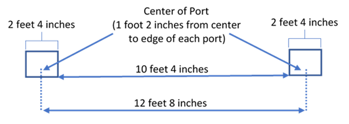
We start with the ports on the lower gun deck, which is where shipwrights started. Pett tells us the ports are 10 feet apart, and that each port is 2 feet 8 inches wide. Therefore, the space between the centers of two adjacent ports on the Sovereign is:
1728743787785.png
This is illustrated in Figure 37.


Figure 37. Ideal Spacing of the Sovereign’s Lower Gun Deck Ports

1728743852787.png

We can now calculate find the location of the foremost port. In placing it, we need to bear in mind that shipwrights did not want to put the foremost gun too close to the stem, because they wanted to leave space for the hawse holes. One maneuver they employed was to place the fore side of the foremost port one-half the interval between port centers plus 12 inches away from the stem. (Fox) This is 7 feet 4 inches on the Sovereign. This spacing does not lead to ports that satisfactorily align with the wales. Better alignment is obtained if we put the first port’s fore side one half interval plus one half the width of a gun port from the stem.[2] This equals 7 feet 8 inches on the Sovereign.

Having located the foremost port, we can turn to the lower gun deck’s other ports. The Pett painting shows that the four foremost ports are closer together than the remaining ports. Closer spacing of the foremost ports is also seen on the other two gun decks. That we can see it on the upper gun deck is particularly important. The ship is barely curving here, so the painting’s portrayal of these ports is not due to a distortion caused by artistic perspective. We obtain reasonable agreement with the Pett painting if we make each of the three spaces between these four ports 9 feet.[3]

The 9-foot spacing of these ports seems to be an effort to prevent the gun arming the lower gun deck’s seventh port from recoiling into the mainmast, which it would do if the ports were 10 feet apart.[4] One consequence of this closer spacing that the weight of the guns was not only concentrated near the stern, it was also concentrated near the bow. This concentration may have caused the decks to eventually hog. This in noted in a 1675 proposal to “raise all her decks to good hanging, which now hog.” (cited in Laughton (Laughton 1932)) The spacing of all lower gun deck ports aft of the fourth port is, as Pett states, 10 feet.

Now that we know the spacing and positions of the lower gun deck’s ports, we can proceed with the ports along the other two gun decks. We saw in Figure 37 that the centers of the lower gun deck’s ports were 12 feet 8 inches apart. This is also the spacing between the centers of the ports on the middle and upper gun decks. Using this, and accounting for the smaller sizes of the ports on these decks, gives us middle gun deck ports that are ideally separated by 10 feet 2 inches, and upper gun deck ports that are ideally separated by 10 feet 4 inches. The details of the spacing of the upper gun deck ports are illustrated in Figure 38.
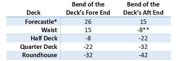

Figure 38. Ideal Port Spacing on the Sovereign’s Upper Gun Deck
1728743910778.png

Positioning the ports on the upper two gun decks is simple. The center of the ports on the middle gun deck lies midway between the ports on the lower gun deck, and the centers of the upper gun deck’s ports is directly above the centers of the lower gun deck’s ports.

There is one exception to this spacing on the middle gun deck and another on the upper deck. The Pett painting shows that the 12th port on the middle deck is moved aftwards.[5] This was most likely done to keep the whipstaff safely away from the recoil path of the gun that arms this port. If the whipstaff were broken, there would be no reliable way to steer the ship. I have therefore moved this port one foot aftwards. The second instance of unequal spacing occurs with the 7th port on the upper gun deck. Equal spacing would cause this port to sever the timbers that support the half deck’s fore end and, therefore, cause the deck to collapse. This port is therefore moved one foot forwards. This position is again supported by the Pett painting.

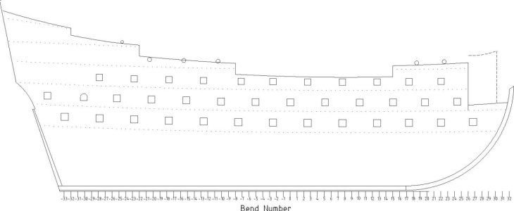
Table 10 gives the distances of the center of the gun ports’ sills from the midship bend. Individual ports are identified by numbers. The foremost port on each gun deck is port #1, the port adjacent to it is port #2, and so on. Figure 39 depicts the ports’ positions.


Table 10. Distances of the Gun Ports from the Midship Bend

1728743954107.png

Note: Ports are numbered from fore to aft. All positions are expressed in feet, from the midship bend. Negative numbers denote distances aft of the midship bend.

Figure 39. The Ports’ Positions
1728744002904.png


Note: More details about the beakhead bulkhead will be provided in a later section. Details about the dimensions of the counter and the heights of the bends’ tops will also be discussed in a later section. The panels, rails, and vertical timbers along the upper decks will be discussed and drawn in later.

The midship bend is labelled as Bend 0. Bends aft of it are denoted by negative numbers. Bends are 30 inches apart.

The Gun Port Lids​

The usual practice in the early 17th century was to place small circular ports along the waist. These ports typically had no lids. (Steere 2005, 19) The gun ports along the Sovereign’s waist were square and had lids on them. The lids are shown by the Pett painting and a later work by Knyff (see Figure 39). Payne does not show lids here. The upper ports, or at least installation of their lids, may not have been finished when he saw this ship. Van de Velde also does not show lids on these ports.

It is not clear if the outsides of the lids were decorated. The Pett painting shows decorations on the outer surface of the gun ports’ lids, and each port has a different decoration. None of the lids’ external surfaces are visible on the Payne engraving or a painting by Knyff, and the only external surface van de Velde shows is the lid on lower gun deck’s bow chase port. He does not show a decoration on its lid. Heywood does not say any of the lids were decorated, but he also notes that “It would bee too tedious to insist upon every Ornament belonging to this incomparable Vessel.”

Whether the inside of the ports’ lids was decorated is also uncertain. Van de Velde depicts them has having St. George’s cross on the upper and middle gun decks, but not the lower gun deck. Payne does not show this but he may have seen the Sovereign before the port lids were on it. The Pett painting does not show any open ports, so it is inconclusive. Finally, Knyff’s painting shows open ports without the crosses.

It is likely that the Sovereign’s port lids were flush with hull when closed. That the ports cut some of the wales, and the Pett painting shows too little room between some of ports and wales to allow the lid to extend beyond the port. An advantage of flush ports is that the ends of the boards that comprise them are not exposed to sea water and, therefore, are less likely to rot than the boards that comprise port lids that are not flush with the hull.


Figure 39 The Sovereign of the Seas as Portrayed by Jacob Kynff

1728744056378.png

It is unlikely that the Sovereign’s gun port lids formed a watertight seal when closed. Such a seal was achieved by clinching the ports. Mainwaring tells us that

“Clinching is, as you would say, a slight caulking and is most used when we are at sea and suspect foul weather so that we may take in water at the ports. We use to command the carpenter to chinch the ports; that is, to drive a little oakum into the seams of the ports which may be done, to serve turn {i.e., to suffice for the purpose], either within board or without board.” (Mainwaring 1922, 125-126)


References​

Deane, Anthony. 1981. Deane's Doctrine of Naval Architecture, 1670. Edited by Brian Lavery. Annapolis, Maryland: Naval Institute Press.

Fox, Frank. Personal Communication.

Laughton, L. C. Carr. 1932. "The Royal Sovereign, 1685." The Mariner's Mirror 18 (2): 138-150.

Mainwaring, Henry. 1922. The Life and Works of Sir Henry Manwaring. Edited by G.E Manwaring and W.G. Perrin. Vol. 2. 2 vols. London: THe Navy Records Society.

Steere, Alisa Michele. 2005. Evolution of Decorative Carved Work on English Men-of-War from the 16th to the 19th Centuries. Master's Thesis: Texas A&M University.


[1] This word usually refers to a type of joint used to join two timbers but, in this case, it means placing a gun port so there is no single point of weakness; see note #3 on page 60 in Deane. (Deane 1981)
[2] This, and other gun port positions are measured along their respective decks.
[3] Nine feet is the spacing that Pennington proposed. He may have obtained his spacing from these ports.
[4] Instead of reducing three spaces by one foot, Pett could have reduced one space by three feet. However, the latter is quite noticeable. Pett’s method does a better job of maintaining the illusion that the lower gun deck’s ports are all equally spaced.
[5] I have numbered the ports so that the numbering begins at the foremost port on each deck.
 
Keep up the good work, Charlie;

To continue on a bit from the last post about fitting the guns, Sir Henry Mainwayring, in his Sea-Dictionary, mentions that if a gun was too low for the port-cill, they would lay a platform of plank on the deck. This was called a bed, the same as the flat plank which formed the bottom of a gun-carriage. Not clear if it raised only the front trucks, or all of them. Maybe that depended upon how much it had to be raised.

Ratty
 

The Sheer Plan (continued)

The Sovereign’s Guns​

Overview​

The Sovereign carried 102 guns. Contemporary production records also show that 102 royal cyphers to put on those guns were paid for. (Calendar of State Papers Domestic 1638) All these guns were made of bronze, which was called “brass” in the early 17th century. The advantage of bronze was that it did not rust, which was important for guns that were at sea. (Kirsch 1988, 58) Besides, the process for making cast iron guns was still in its infancy at this time.

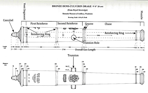
Ninety-eight of the Sovereign’s 102 guns were made by John Browne. The remaining 4 guns, all 10 foot long, fortified demi culverins, were made by Thomas Pitt who worked as a subcontractor for Browne (Caruana 1994, 64) and, therefore, were likely of Browne’s design. (Fox, Personal Communication) Browne’s design is distinctive because of the layout of its reinforcing rings, and its unique cascabel (Figure 41). Another feature of Browne’s guns is that their external taper does not form a single angle that runs along the entire length of the gun. There is no taper near the gun’s vent on Browne’s guns. The taper then increases in the gun’s next segment (the first reinforce), and increases again at the segment containing the trunnion hole and royal cipher (the second reinforce). The gun’s greatest taper begins at its next segment (the chase), and runs to the muzzle.


Figure 41. Dimensions of A Demi Culverin Drake Cannon from the Sovereign of the Seas
1729263109909.png
Adapted from Caruna (Caruana 1994)

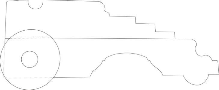
A detailed discussion of 17th century guns can become complicated, and is beyond the scope of the present project. For the purposes of this discussion, we can think of the Sovereign’s guns as falling into two main categories, those that were drakes, and those that were not. Drakes were invented by John Browne. They had relatively thin walls and tapered towards the rear of the chamber. Their reduced amount of metal allowed them to be manufactured at a lower cost than conventional guns. (Caruana 1994, 61) It also made them lighter and, therefore, smaller ships could carry relatively large calibers of them. They were not used much in countries outside of England. Drakes were not intended to provide substantial broadside power, even though the Sovereign could fire one. They required only three-fourths of the standard charge, so they were also limited at long range. This type of armament was for melee-type battles. (Caruana 1994, 64) Firing one of these guns also provided a dramatic demonstration of Sir Isaac Newton’s soon-to-be-discovered third law of motion; for every action, there is an equal and opposite reaction. Drakes had a “vicious” recoil. They would even burst if shot jammed in the mouths of their chambers. (Fox 2009) Because of their recoil, drakes sat on special gun carriages designed to contain it. These carriages had trucks (wheels) at their front, and a skid at the rear. If the gun had to be moved, its rear end was jacked up and ordinary trucks were put on its axles. (Caruana 1994, 181)

Figure 42. A Drake Gun Carriage
1729263219664.png

Drawing adapted from Caruana (Caruana 1994, 181). Caruna’s drawing also appears in Septhon. (Sephton 2011, 115)

If the drake’s recoil was vicious, the recoil of guns known as “cutts” was even worse. Cutts were another lightweight weapon. They were lighter because they were relatively short. Many of them were produced by simply sawing off about 3 feet from an ordinary gun, often a 9-pound culverin. Their recoil was so violent that it often caused them to fly from their carriages. Not surprisingly, their production was eventually (but not immediately) stopped because of this. (Fox 2009)

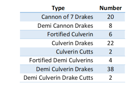
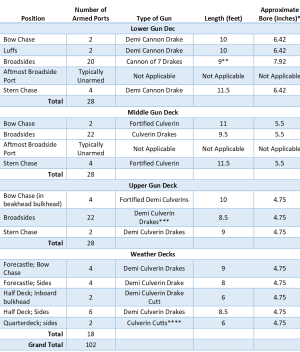
There were 8 types of guns on the Sovereign (Table 11). The heavier guns were placed lower on the ship. These were cannon of 7. The Sovereign was the first ship to carry them, and it could do so because it was so big. Some of the guns were “fortified,” meaning that their bore walls were thicker than those of a non-fortified gun of the same type.


Table 11. The Guns of the Sovereign of the Seas

1729263264232.png

Gun Placement​

Misconceptions about how the Sovereign’s guns were placed on each of its decks are common. The most common of these is the belief is that the bow chase ports on the lower gun deck were unarmed. Its popularity is attested to by a Wikipedia entry (Wikepedia 2021) that says that “The shape of the bow meant that the foremost gun ports on the lower gun deck were blocked by the anchor cable,” and that is repeated verbatim by at last 12 different internet sites, including that of a kit manufacturer. (Zaric 2019) The argument may have originated from Sephton, who says that “Payne is presumptuous in depicting a piece protruding from the foremost gun port on the lower gun deck, adjacent to the hawse-holes,” and then adds “Because of the inwards curvature of the bow strakes, the foremost port on the lower gun deck was hindered by the anchor cables passing through the adjacent hawse-holes and along the lower gun deck. Therefore, the fore chase …. was mounted in the second port from the stem…” (Sephton 2011, 102)

The foremost port was not hindered by the anchor cables. The fore chase guns were aimed straight forward. Their barrels were parallel to the knee of the head and, therefore, parallel to the anchor cable, which ran alongside the gun, not behind it. Further, leaving the bow chase ports unarmed did not become common until the time of the line of battle. The Sovereign was built before then. Since the enemy could come from the front or the rear, the ability to ward off attacks from these directions was of the utmost importance. Accordingly, the bow chase ports in ships of the Sovereign’s time were always armed. (Fox)

It was the aftmost ports on the sides of the lower gun deck that were unarmed. (Anderson 1913) (Fox) The stern chasers were shifted to this position when needed. (Fox) This arrangement was necessary because there was not enough room to simultaneously arm both the stern chase ports and the aftmost ports on the ship’s side. If both were armed, firing one of the guns would cause it to recoil into the other one. This is also true for the aftmost ports on the sides of the middle gun deck. As with the lower gun deck, the stern chase guns could be shifted to them if necessary. (Fox)

Another area of confusion is how many guns protruded through the beakhead bulkhead and the level of the upper gun deck. Both the Pett painting and the Payne engravings show four gun ports here. The van de Velde drawing shows six ports but, as previously discussed, it does not represent the Sovereign as initially built. As discussed later, the bulkhead may have been revised when the beakhead was revised during an earlier repair. Consequently, there were initially only four guns in this bulkhead on the upper gun deck.

A possible distribution of the Sovereign’s armament is shown in Table 12. There is less certainty about this arrangement than most sources admit. Even setting aside the difference in the chase port armament, different sources show different patterns. I have based my pattern on information supplied by Frank Fox (Fox) but, since other arrangements are also plausible, some remarks about it are in order. First, the stern chase guns on the lower and middle gun decks are the longest guns on these decks. This is because they project over the helm port and wing transoms. These, and particularly the wing transom, were very large timbers. The middle’s gun deck’s chase guns also need to be long because the must safely project beyond the curving counter. Second, the bow chase guns on these two decks are also relatively long. This is because these guns point forwards. Since their ports are along a highly curved part of the hull, the side of the port nearest the stem is further away from the gun carriage than the other side of the port. A longer gun is therefore required to clear the side near the stem. Third, the two demi culverin drake cutts, which are the lightest guns on this ship, were likely on the half deck or quarter deck. They pointed forward to the waist as a last defense against boarding. (Fox) They are facing inboard because they were loaded with cannister, and the cannisters were filled with round lead or iron balls like a shotgun shell. This kind of shot was used against boarding parties because it covered a wider area than a cannon ball, and did not do as much damage to the ship as guns that fired shot. Finally, the two other cutts on the Sovereign, the culverin cutts, were only six feet long. This is too short to safely project through the hull on the lower decks, (Caruana 1994, 64) so they must have been on an upper deck.

The lengths of all the Sovereign’s guns are also not known with certainty, (Caruana 1994, 62) and their bores are even more uncertain. Table 12 shows the bores for guns of the same type as on the Sovereign, though not necessarily for guns manufactured by John Browne, because they may be of interest to modelers, but they are speculative.

Finally, the weights of different cannon of 7 drakes are markedly different. This shows they were not all the same, though their exact differences are uncertain. This is also true of the Sovereign’s demi cannon drakes, which apparently came in more than one pattern. (Caruana 1994, 62)

The Sovereign likely also carried some smaller guns not listed in Table 12. These guns are not identified in contemporary lists, but they were probably small swivel pieces and/or another type of small gun called a “chamber piece.” (Fox) These may have but what Heywood was referring to when he said “She hath thirteene or foureteen ports more within Board for murdering peeces.”


Table 12. Possible Distribution of the Sovereign’s Guns
1729263342377.png
*Bores are taken from appendices 24, 25, and 26 of Sephton. (Sephton 2011)
**The Sovereign’s cannon of 7 drakes came in three lengths that ranged from 8 ½ to 9 ½ feet. I have listed 9 feet because this was probably the length of most of them. (Caruana 1994, 62)
***The Sovereign’s demi culverin drakes came in three lengths, 8, 8 ½, and 9 feet. I have listed only the median length of 8 ½ feet.
****These guns could have been on quarterdeck instead of the half deck.

References​

Anderson, R.C. 1913. "The Royal Sovereign of 1637." The Mariner's Mirror 3 (6): 168-170.

Calendar of State Papers Domestic. 1638. Charles I, 1637-8. Vols. 387, April 1-17. Edited by John Bruce. Her Majesty's Stationery Office, 1869. London: British History Online, Charles i - volume 387 April 1-17. Accessed June 20, 2020. British History Online, http://www.british-history.ac.uk/cal-state-papers/domestic/chas1/1637-8/pp341-369.

Caruana, Adrian B. 1994. The History of English Sea Ordnance, 1523-1875, Vol 1. Rotherfield, England: Jean Boudroit Publications.

Fox, Frank. Personal Communication.

—Personal Communication.

—. 2009. The Four Days'Battle of 1666: The Greatest Sea FIght in the Age of Sail. Yorkshire: Seaforth Publishing.

Kirsch, Peter. 1988. The Galleon. London: Conway Maritime Press, Ltd.

Sephton, James. 2011. The Sovereign of the Seas. Stroud: Amberly Publishing.

Wikepedia. 2021. "HMS Sovereign of the Seas." Wikepedia. March 29. Accessed Octobr 19, 2024. https://en.wikipedia.org/wiki/HMS_S... them were twenty cannon,45.7 tons (45700 kg).

Zaric, Kristina. 2019. De Agnosti Model Space. August 9. Accessed February 27, 2021. https://www.model-space.com/blog/2012/08/sovereign-of-the-seas-armaments-of-the-warship/.
 

The Sheer Plan (continued)

Wales​

Overview​

The wales are important structural components of a ship. The Treatise tells us that they are “long pieces of timber scarfed together in divers places and made one entire piece reaching from stem to stern, which are used not only to grace the ship’s side without board but for strength also by bolting the knees of the decks unto them, and for keeping fast the upper ends of the futtocks and navall timbers.” Despite having this function, wales did not always follow entire decks.

The main wales were highly curved at the bow and they had a special name; the harping. In the Treatise’s words “the harping is the fore part of the wale from the luff to the stem, which because it roundeth more than the rest of the wale must be a special piece of compass timber[1] and is distinguished by a peculiar name.”

The Treatise and Deane describe methods for drawing the wales. Though their rules are not the same, both draw their wales as concentric circles. This is a bit of a simplification. Often, the lower channel wale separated from the upper main wale as it moved aft. This is seen in both Keltridge’s and Battine’s manuscripts. We can expect little else beyond these qualitative descriptions to apply to the Sovereign. The specific, quantitative courses the wales followed were tailored usually tailored to each ship. (Fox)

General Course of the Sovereign’s Wales and Rails

Ideally, we would like to know the system that Phineas Pett used to draw the Sovereign’s wales and rails. Since such a system is never elaborated on plans, this is not possible. Therefore, it is helpful to provide a set of rules for how they were drawn in the current reconstruction. They may give insight into the rules that Phineas Pett used.

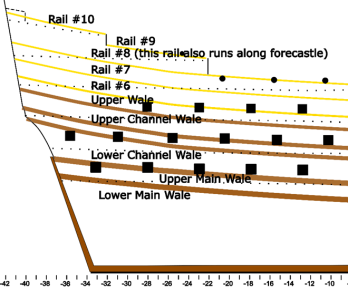
On a qualitative level, the Sovereign’s wales and rails partly follow the pattern described above. They all form the concentric circles described by the Treatise and Deane from the bow to the beginning of the lower quarter galleries. [2] Thereafter, the upper and lower main wales continue along their circles to course upwards to the helm port and wing transoms, respectively, while the lower channel wale separates from these two wales to reach the counter. This is the sort of rise described by Keltridge and Battine but, as we will see below, it is much larger. All the wales and rails from the lower channel wale upwards are parallel. Drawing wales and rails like this requires us to know only the courses of two of wales; one of the main wales, and the part of the lower channel wale that begins aft of the lower quarter gallery’s fore end.

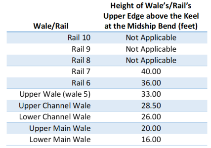
Pett would have produced his circles by defining three points, one at the bow, one at the stern, and one somewhere between these two. He seems to have used their heights at the midship bend for these latter points. Describing this is clarified if we name the wales and rails. The names I have used are given in Figure 43. The lowest five items (from the bottom up) are wales. Thereafter come the rails. These are: rail #6, rail #7, part of which runs along the top of the waist, rail #8, part of which runs along the tops of the forecastle and half deck, rail #9, which runs along the quarter deck, and rail #10, which runs along the roundhouse.


Figure 43. Naming the Sovereign’s Wales and Rails
1729864265677.png

From here, we can examine how far their top edges are above the keel at the midship bend (Table 13). We can see that their courses are all described by arcs that lie at simple heights. There are no factions of inches and the most complex height is simply a one-half foot interval. Such “clean” heights are unlikely to arise by coincidence.

Table 13. Heights of the Wale and Rail Tops at the Midship Bend
1729864341349.png
*Heights are from the top of one wale to the top of the wale above it. A 17th century shipwright would have arrived at the same result by considering the space between wales and rails.

The Upper Main Wale​

Shipwrights started drawing the wales by first drawing the lower main wale, but I started with the upper main. This is because we have several landmarks we can use to position it. The first of these is the helm port transom. The upper main wale’s aft end was always here.

The second landmark is the height of the lower gun deck’s beam at the midship bend. The Pett painting shows that the beam was a little below the wale’s center. It is 1 ¼ inches below the wale’s center on the current plans and, therefore, the wale’s center is 1 ¼ inches above the height of the breadth. As shown in Table 13, the wale’s top is 20 feet above the keel.

The third landmark is the fore height of the breadth. This height is important because the fore end of the upper main wale in ships of this era was usually at or near it. The Newton Manuscript says the wale must “lye neare about the breadth.” A survey of the Royal Navy conducted by Edward Battine in 1684. (Endsor 2020, 109) found that the upper edge of this wale was here. Bushnell tells us that “the height of the breadth from the Mid-Ship forward is the lower Edge of the upper Waal,” so the fore end of this wale’s lower edge is at the height of the breadth. Deane’s wale is intermediate; he puts the fore height of the breadth “something above the lower edge of the upper wale,” meaning that the wale’s bottom is a little below the fore height of the breadth. The Treatise’s does not directly comment on the height of this wale at the bow. The lower edge of the upper main wale in the current reconstruction is about 3 inches below the fore height of the breadth. This is consistent with Deane.

We can use the gun ports to confirm the wale’s course. All contemporary artworks show that the Sovereign’s upper main wale was cut by some of them. The Sovereign’s upper main wale in the current reconstruction is cut as shown in the Pett painting, and this is a consequence of making its lower gun deck flush. The Treatise’s author tells us that this will happen, and admonishes against it by saying “to lay this deck flush fore and aft cannot be done without cutting the wale, which is both disgraceful and a weakening to the ship. The best artificer that ever was[3] used a fall for the gun room abaft and a rise for the chase afore, and these bring all things well to pass and a greater strength to the ship than a flush deck…” Despite this, the Treatise’s author does allow for the possibility of flush decks and, therefore, wales that are cut by ports, when it tells us that “every man may please his fancy.” The older Newton Manuscript also admonishes against cutting the wales. It tells us that “They must ever contrive the laying of the orlope & the deck that you do not cut the wales nor the channels with ye portholes, for it is not sightly in a ship.”

Cut wales are not unique to the Sovereign, and expressions of concern about cutting them seem to have lingered longer than the unwillingness to cut them. Deane’s drawings show the upper main wale cut by gun ports in a similar manner, leading him to explain that “the wales being so laid will be well fastened to the knees in hold, being placed against them, and besides, the ports will cut but little of them abaft.”

The upper main wale is also cut on Bushnell’s ship, even though he also recommends against this when he tells us to “first set off the Ports, in their places, that the Waal may lay above the Ports, or else he would be cut with the ports in pieces.” In fairness, though, Bushnell may have been more concerned with keeping the lower main wale intact.


The Lower Main Wale​

The lower main wale is parallel to the upper main, so the former’s position is determined from the latter. The two wales are separated by 2 feet 8 inches. The spacing is confirmed by the Pett painting and the Payne engraving. Both show that the upper and lower main wales are separated by a distance equal to the height of the gun ports on the lower gun deck, which is 2 feet 8 inches. This is the spacing recommended by the Treatise. The older Newton Manuscript tells us that “the two lower wales must never lye further asunder than two foot & half in any ship…” Bushnell would place the wales “one foot and an half asunder.” Deane uses a system in which the spacing of the wales depends on the breadth of the ship. According to his system, the wales would be 30.78 inches apart on the Sovereign. He would likely have rounded this to 2 feet 8 ¾ inches, or maybe even 2 feet 8 inches, which is their spacing on the Sovereign.

The Pett painting shows that lower main wale is below the water at the midship bend. It is 8 ¾ inches below the swimming line at the midship bend on the present plans. The lower main wale courses from here to the wing transom, which was always the case in ships of this era.

The Pett painting suggests that the Sovereign’s main wales were 16 inches wide.[4] This contrasts with the Treatise, which tells us that the main wales should be 1 foot wide, and with Deane, who would have us make the wale ½ inch wide for every foot the ship is broad. This works out to approximately 23 inches for the Sovereign.

A list at the Admiralty suggests that the Sovereign’s main wales were 11 in. thick. (Laughton 1932) The planking, known as “thick stuff,” was thicker here.


The Lower Channel Wale​

All contemporary works show that the lower channel wale rises to the counter’s top as it runs aft. It does so by rising quite a bit along the lower quarter gallery. The Pett painting shows this. The wale’s top is a little below the middle gun deck’s eleventh port (which lies just before the galleries), and then climbs to where it is above the top of the aftmost port. The wale must therefore rise by the height of more than one gun port (2 ½ feet) over the 22 ½ foot distance between these two gun ports. This rise is about the same as rise of the wale from the midship bend (the midship bend is near the large crease in the Pett painting that, in turn, is near the waist’s center) to the lower quarter gallery’s fore end. This latter rise is about the height of one gun port over a 65 foot span. Since the wale is characterized by a gradual rise followed a rapid rise, it cannot be drawn as a single arc. Pett must therefore have drawn the part of the lower channel wale that runs under the quarter gallery as a separate arc.

This steep aft rise of the lower channel wale differs from Deane and the Treatise. It also differs from William Keltridge’s wale. His lower channel wale rises so its lower edge is two inches further from the upper main wale at the stern than at the midship bend. Battine describes a 4 inch rise in the channel was at the stern.

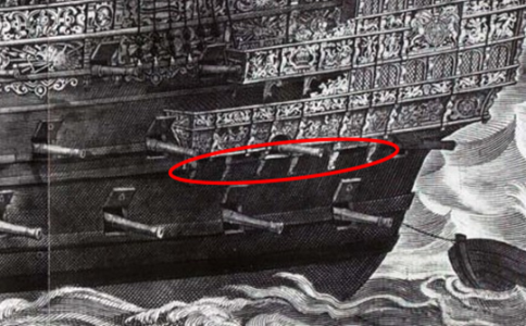
The rise occurs because the fore end of the gallery’s extension is near the middle gun deck, and the gallery must be carried up to the half deck where there is an entry door to it. The lower channel wale follows the gallery along this course to provide a thick surface to which supports (probably angle brackets made of iron) for the heavy gallery are bolted. The ordinary (and relatively thin) hull planking would not have been able to support the gallery’s weight and, therefore, the brackets, could have torn loose. These supports are visible on the Payne engraving, and are circled in red in Figure 44.

The lower channel wale also rises to also provide support where the top of the counter meets the upper stern at the ship’s sides.


Figure 44. Gallery Supports on the Payne Engraving
1729864419063.png

Shipwrights sometimes rotated their bows when the drew the lower channel wale, so it was closer to the upper main wale at the bow than at the stern. This is implied by Keltridge. Although the aft end of his wale is two inches further from the upper main wale, its fore end is 4 inches closer. This is not seen on the Sovereign.

The Pett painting suggests that the two channel wales were 10 inches wide. That they are narrower than the main wales follow the contemporary practice.

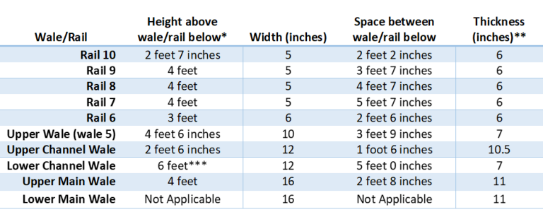
Every wale and rail above the lower channel wale is parallel to this channel wale, so no further discussion of them is required. Their widths, as suggested by the Pett painting, and their possible (albeit speculative) thicknesses are shown in Table 14.


Table 14. Some Possible Dimensions of the Wales and Rails

1729864483578.png
*Heights are the heights from the top of one wale/rail to the top of the wale/rail below.
**Thicknesses of all items except the main wales are from Keltridge.
***The height of the lower channel wale above the upper main wale is the height from the bow to the beginning of the lower quarter gallery. All other heights are constant across the length of the ship.

References​

Endsor, Richard. 2020. The Master Shipwright's Secrets. New York: Osprey Publishing.
Fox, Frank. Personal Communication.
Laughton, L. C. Carr. 1932. "The Royal Sovereign, 1685." The Mariner's Mirror 18 (2): 138-150.


[1] Compass timber is curved timber.
[2] Here, the Pett painting provides an example of how difficult it is to interpret art work. It shows that the gap between the upper main wale and the lower channel wale increases between the midship bend and aft bend 26. However, it also shows that the tops of these two wales are parallel. Both cannot be correct. The increase in the gap is an artifact. It happens because the upper main wale on the painting becomes thinner as it approaches aft the lower quarter gallery’s fore end.
[3] The “best artificer” may be Matthew Baker (Kirsch 1988, 166)
[4] Measurements of the widths of all wales and rails on the Pett painting were made at the midship bend.
 
Back
Top