A Dutch Fluyt in shell first, reconstructing the "Ghost ship" scale 1:36

Thx again everybody for comments and likes.
Today the topic will be "stuurlast" this means the vessel has more draught in the stern as in the stem creating a rudder which is deeper in the water.
The stuurlast for Dutch ship was by rule of thumb 1 foot per 50 feet lenght. With this ship measuring 95 Amsterdam feet the stuurlast would have been 1,9 amsterdam foot or 54 cm.
To create the stuurlast in my hull I have repositioned the keel, this as the lower part of the ship is sunken in the silt and can't be seen in the wreck site drawings. So the upper part of the hull remains as it is follow the drawings and the keel is lifted on the forward side to create the needed stuurlast.
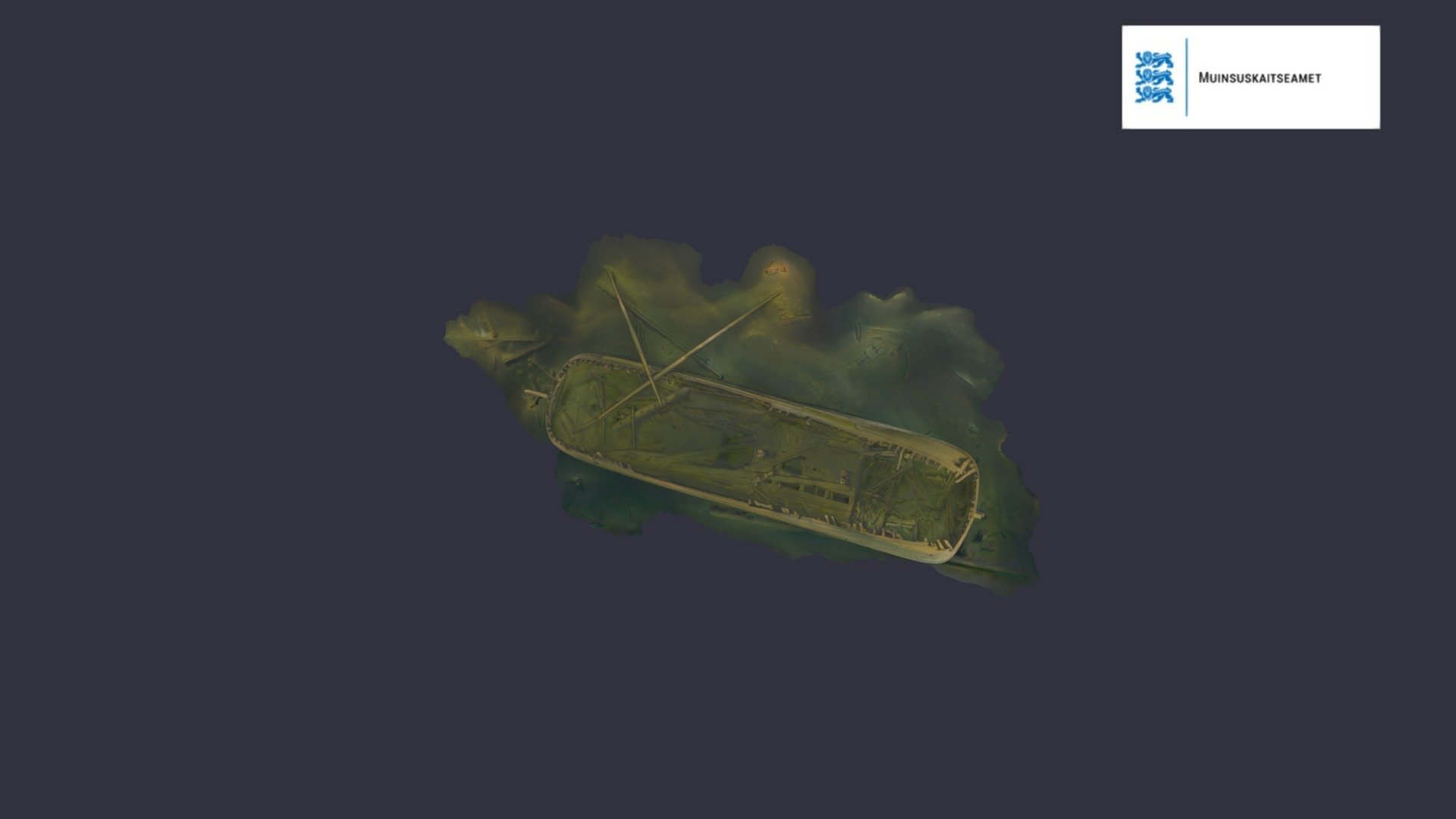
The white line you see at the stem at water line height and in the stern just above the keel is the seabed, this is how far the bow is sunken into the silt.
Stuurlast.jpg

Now you can also see why my fwd/aft line plan is showing this jump in height between the frames, this is a direct result of the stuurlast.
Spant constructie.jpg

The next step is placing the decks.
We have seen Nicolas Eriksson already made a cross section drawing which I used to create the internal deck structure. This I combined with Witsens proportions.
Witsens mentions the depht of the hull is 1/10 of the length. The depht of the hull is the top of the keel towards the top of the deckbeams in the side of the ship. In my ship this should be 9,5 foot and this is directly the height in the hold of this fluit which was around 2,7 mtr. The deck in between is called the overloop or koebrug and this deck was very low in height only around 5 feet which is +/- 1,4 mtr (ask Paul @dockattner as he experienced on the Batavia).
The koebrug dek was used to store the cargo which cerntainly needed to keep dry as possible. On East Indiaman this was used for the spices on my humble fluit, which most probably is a wood trader, this was used to carry planks as we can can still see up to today on the wreck of the fluit Anna Maria where there is stil a load of sawn planks stacked in place on this deck.
Anna Maria wreck.jpgAnna Maria koebrug.jpg

OK back to de Zwaan
To place the decks I have used Erikssons drawings and placed the decks according his drawings. I had to do some minor fine tuning to fullfill the Witsen proportions. My result led to a depth of 9,8% of the lenght or 9 1/4 foot and a koebrug of 5 foot. I try to get proper rounded figures as people in the 17th century didn't work with a metric system of decimals so I expect a height was 9 1/4 foot and not as I calculated 9,31 :cool:
Zwaan dekken.jpg

The deck of the hut is under discussion. Ab Hoving expected it to be following the same lines as the other decks but in the drawings of the wreck you see two planks one on eack side of the hull which is fitted between the frames and therefore the only remaining part of the deck of the hut stil in place. These planks are following the same of the deck I show in my drawing above. The curvature of the deck of the hut is taken from the curved hut deck beams which are scaterred around on the half deck. Due to the curvature and the steep rising deck line you get a little bit more space to stand straight up in the hut.

If we look at the decks in 3 D we see the sheer of the main decks. The deck in the accomodation are flat and don't follow the sheer. You see this is more common on Dutch ship where in the stern section the deck are more flat which also would improve the habitability of the cabin and the hut.
Zwaan dekken perspectief.jpg
To be continued
 
Last edited:
Very interesting indeed Maarten. The stern section with the flat deck vs the whole deck following one sheer line is also one of the main differences in interpretation between De Weerdt and Hoving as far as the deck of the WB goes. De Weerdt has it in two parts while Hoving has it as one.
 
Haha that seems to be allways a discussion. Even on the sovereign of the seas there are two options about the run of the decks.

At least I am lucky here to have an actual wreck.

I have more drawings of measured fluit wrecks in the baltic and will make a slight comparence.
 
You are indeed fortunate Maarten. The existing wreckage of the WB is in a museum in St Petersburg and apart from an initial visit made to Russia by some Dutch researchers, nothing further has been done about this. This is almost as difficult to believe as the fact that the WB is nameless. :D
 
See here the measured wreck of the "Lion wreck", this is a smaller fluit which is sunken in the Stockholm archipelago.
Lion wreck.jpg

Secondly I have a contemporary drawing of Ake Ralamb, the Ralamb's fluit. Here you see a straight run of the deck. So you see both are possible.
Ake Ralamb Fluit.jpg
 
Correct Maarten. And what makes it so interesting: You would think that the straight deck at the stern would be on larger vessels, where the deck would have too much of a sheer for the gun carriages (if applicable) to stand level, but now you say the Lion wreck was the smaller of the two :D - confusing!
 
Next step in the reconstruction are the wales, this will be the last step in my 3D drawing to be able to start with the build.
For the wales position I use again the Eriksson drawing of the side view of the wreck.
zijaanzicht.jpg

After several hours shaping, checking etc etc the wales are in the drawing.
PS view wales.jpg

And how they look on the hull
PS view.jpg

Romp met berghouten voor.jpg

Romp met berghouten achter.jpg
Achterzijde.jpgBovenaanzicht model.jpgOnderzijde.jpg

Looking at the wales and the decks you see the lower koebrug deck is situated lower then the wales, I discussed this with Ab Hoving who mentioned this was more common for the koebrug deck.
The main deck is nicely fitted just between the two top wales allowing the deck clamp on the inner side of the second wale from the top.
See below the 3D view of the decks and wales, the red one is the gun wale.
Romp met dekken en berghouten voor.jpg

For the shell first build first the keel wil be layed and stern and stem raised. later in the proces the "scheerstrook" is fitted showing the biggest breadth of the hull. This scheerstrook is situated between the two lower wales, this is the reason I need the flow of the wales on the hull to enable me to correctly fit the scheerstrook later in the process.
Romp met onderste berghouten voor.jpg

Next time I will discuss the shell first build methode. After that I will start to recontruct the keel, stem and sternpost.
 
Thx again for all comments and likes allthough my blog is still boring without any saw dust and heavy machinery.

But as promissed today I will discuss the shell first building methode which I will use for my build.

In the Northern part of Holland, which was more or less Amsterdam and up to the North, the shell first methode of building was used throughout the 17th century. It was done as it was quick, easy and already in use for ages.

In the drawings below, which are from Ab Hovings book about Witsen (a must have for people building Dutch shipmodels) clearly show the methode in detail.

First like with any build the keel is laid and the stem and stern post fitted.
20220630_202335.jpg

But then things will be different. Instead of starting to set up frames we start with the first planks including the rabbet. 6 rows of planks on both side of the keel. These planks we keep in place with small strips of wood. This part of the shell we call in Dutch "het vlak" therefore this building methode is also called de vlakbouwmethode.
20220630_202443.jpg

At het vlak the first main frame member is fitted in Dutch we call these lower frame part "liggers" or floors in English.
At the edges of the hull two "zitters" are fitted which are shaping the contour of the main frame towards the side of the hull.

Now the next 3 rows of planks are fitted on both sides of the hull. These 3 rows are called " het boeisel der kimmen" which are shaping the hull from the flat bottom towards the sides.
20220630_202521.jpg

In Witsens original drawings this looks like this.
20220630_202548.jpg

In the picture below you can see this on the build of the Barentz replica.
eerste-zitter.png
inhouten.png

Now the bottom shell is finished and it can be filled with "de liggers en zitters" or lower frame parts and curved frame parts.
For a few selected frames the "oplangen" or vertical frame parts are fitted. It will suprize you but these are nearly the same in shape over the major length of the ship. To these oplangen the "scheerstrook" is fitted.
The scheerstrook is one of the most important steps of the build. This is controlling the shape of your entire hull. The scheerstrook is fitted in the space between the two main wales, or to be more precise later in the build the two main wales will be fitted above and below the scheerstrook. The shape of it determines the shape of the hull, therefore I drew the wales into my 3D model, this to have a reference for my scheerstrook setup during my build.
20220630_202702.jpg

After this the rest of the hull can be filled with oplangen. It now starts to look like a ship.
Boeg_Willem_Barentsz.jpg

On top of the oplangen the next frame part is fitted called "stekers". These stekers reach to the top of the hull. To shape the upper hull additional strakes are used, these are called "centen" and shape the upper part of the ship while the stekers are fitted.
20220630_202806.jpg

All these frame parts are only fixed to the outer planking and not to other frame parts.

Now all the frame parts are in place the planking continues up to the main wales.
20220630_202858.jpg
B-JaJaFo-160711_Barentszschip1.jpg

The ship is now ready to get into the water and make room for the next one.
 
Last edited:
A Long time ago since I posted on this upcomming build, but I am still doing a lot of work behind the scenes.
Currently I am especially gathering a much data as I can get on period build wreck sites which let me already to some very interesting digital archives, museums etc.

I also found an additional Fluyt wreck in the Baltic which sank 2 nd Q of the 17th century near Tallinn Estonia.
This wreck I found via Sketch Fab, the Estonian heritage committee made a 3d model of the site on sketchfab, which you can find here.
You directly see this is a fluyt by the shape of the stern where the upper frames are creating a very strong tumble home which is so characteristic for the fluyt.

What for me is very interesting about this wreck is again it preservation in combination with the upper part which fell of in time, this allows you to see the structure at a different level then in the other wreck and help you to determine the structure of the hull at different frame positions. The Ghost ship (swan) wrekc is preserved nearly complete including half deck and fore castle deck. This wreck is preserved up to the main deck so you can see below the fore castle deck and look into the great cabin. You can clearly see the bow and stern cant frames. You can even see from these frames that these are following the line of the outside planking which point to shell first building, but I will come back on that later. Typical Dutch shape of fluyt with blunt bow and stern.
413210.jpg

Different wrecks in different stages of preservation show all very valuable information for my reconstruction.
First we have Anna Maria in Sweden.
Anna Maria was exploded after her crew left her in port while visiting the local tavern and kept the fireplace onboard burning, OEPS.
bovenaanzicht.jpg
Luckily for me I can now see the frame construction towards the keel in the stern section :cool: .
zijaanzicht.jpg
You can see here that the frame member are not connected to each other but only to the outside planking. You can see the frame structure clearly.

achteraanzicht.jpg
I can measure the height of the hold to the orlopdeck and even the space between orlop and main deck, and use the ratios for my reconstruction and compare them to the data Witsen provides.

vooraanzicht.jpg
On the bow you see the bow frames ad there position clearly following the shape of the outside planking in their placement. To me this means the shape of the planking was there before the frames were placed. These frame do not follow the same line as the stem, they are not perpendicular to the water line but but placed to create and even spread in the pre determined shape, read shell first.

The Tallin wreck is a s said more complete, we move from the hold and orlop deck to the main deck, but the half deck and fore castle are missing.
Zijaanzicht.jpg

The bow of this ship show exactly the same construction around the hawser holes as the ship I am going to build, and these part seemed to be carved. The top wale is showing a rounded shape.
Boeg.jpg
225352.jpg

The frames in the stern and bow show the same positioning as in the Anna Maria bow following the shape of the planking which I marked below.
The stern section below.
Stern above marked.jpg

The bow section
Frame positions bow marked.jpg
The blunt bow and stern are again comparable to the Anna Maria and the Ghost Ship (Swan).

The stern with its default cargo doors in the rear used for loading planks and tree tree trunks into the hold and on the orlop, which went through the great cabin. The smaller openings above are the cabin windows.
Stern, double planking.jpg
It look like this ship has a second layer of planks as ther eis nearly no difference between the lower wale and the lower hull planking below the wale. I have read this is also the case for the Ghost Ship. In theory yu wont expect it for baltic traders as they are not prown to the famous ship worm. I have to dig into thos more to get an explanation, maybe the strenght of the ship in ice would be a reason.

Next time I will show more interesting construction details and other sources of research material.
 
Last edited:
Dear Maarten

Now this the type of research that I can spend hours reading. You are very fortunate in having such well-preserved wrecks to work from - with your through research, interpretational skills and computer literacy, I know that this these will be an expertly crafted set of plans - much better than what so called historians can come up with.
 
Back
Top