I will sit behind you and I have duct tapeVery interesting ship and should be a great build to watch. I am in! Cannot promise to sit quietly
-

Win a Free Custom Engraved Brass Coin!!!
As a way to introduce our brass coins to the community, we will raffle off a free coin during the month of August. Follow link ABOVE for instructions for entering.
-

PRE-ORDER SHIPS IN SCALE TODAY!
The beloved Ships in Scale Magazine is back and charting a new course for 2026!
Discover new skills, new techniques, and new inspirations in every issue.
NOTE THAT OUR FIRST ISSUE WILL BE JAN/FEB 2026
You are using an out of date browser. It may not display this or other websites correctly.
You should upgrade or use an alternative browser.
You should upgrade or use an alternative browser.
A Dutch Fluyt in shell first, reconstructing the "Ghost ship" scale 1:36
- Thread starter Maarten
- Start date
- Watchers 74
-
- Tags
- dutch fluit
Oh Ho
interesting project - I will follow your work of research and build with big interest
interesting project - I will follow your work of research and build with big interest
Thx gents for all your likes and comments but it is still a long time before first dust.
In the coming time I will show more about how to create the shape of the hull as good as possible with the available data.
In the coming time I will show more about how to create the shape of the hull as good as possible with the available data.
- Joined
- Oct 15, 2017
- Messages
- 1,191
- Points
- 443

I too will be watching, with excitement. Your Royal Caroline build demonstrated your "courage in creativity" with wonderful results. An "experimental" ghost ship build with shell first construction offers you even more creative license! I am super eager to watch and learn as I've decided to start a "shell first" scratch build soon myself. I can think of no better pioneer to follow.
Cheers,
Ken
Cheers,
Ken
- Joined
- Apr 20, 2020
- Messages
- 6,242
- Points
- 738

Dear Maarten
Joining the compliments of our dear friends, indeed seems to be a very interesting and challenging project, I have no doubt that I can learn a lot from you. I would be happy if the documentation of the working methods and results would be as detailed as possible with as many photographs as possible. Promises to be an attentive student and no matter what row I sit or stand in the stands, the main thing is to absorb from your knowledge and experience a friend.
Joining the compliments of our dear friends, indeed seems to be a very interesting and challenging project, I have no doubt that I can learn a lot from you. I would be happy if the documentation of the working methods and results would be as detailed as possible with as many photographs as possible. Promises to be an attentive student and no matter what row I sit or stand in the stands, the main thing is to absorb from your knowledge and experience a friend.
I’ll be sitting in the corner. Just like when I was in school or in trouble at home.
Thx for all the comments and likes, see there is a lot of interest and a lot of questions for a build like this as it ended up as most viewed topic last week, so I hope I don't let you all down  .
.
As mentioned the choice will be the Ghost Ship or actually most probably the Zwaan (Swan) as a carved body of a swan had been detected next to the stern of the ship.
Ok lets discuss sources, luckely we have internet nowadays and I have spend hours and hours on internet to collect as much data as possible, secondly I received research data from Dirk Wuyts which he used for his ghost ship build and the last source is the knowledge of Ab Hoving from himself and his books especially his Witsen book and ships of Abel Tasman book, very usefull resources.
From the internet I found archeological papers from Niklas Eriksson which I also briefly contacted via email his publicly available papers provide a lot of data and some countour drawings of the wreck site. These drawings were made from the 3d sonar scanning of the wreck site, so these should be accurate.
The wreck site is scattered with parts of the ship which fell of after she sunk or in the following 350 years after.
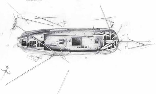
Secondly there is a top view drawing with a scale. This is a drawing of the wreck site which he published in his paper which you can find via Academia.edu
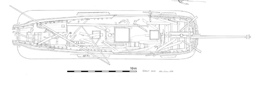
From this drawing you can clearly see the top deck arrangement but also the outer shape of the hull with its ver blunt bow and stern which are essential to reconstruct the shape of the ship in a later stage. As planks are missing also the deck beam positions can be reconstructed, you can see the beams and smaller carlings in between. From the deck of the hut you can see the rounded deck beam laying on top and you can recontruct the curvature. Even the mizzen mast is on the deck as are the spars which are even more visible in the wrecksite drawing above.
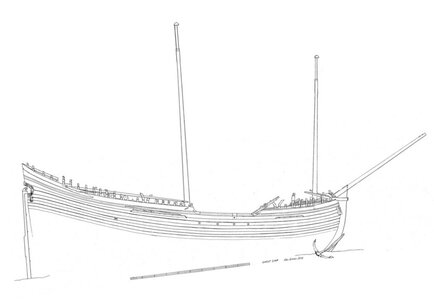
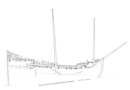
From this paper there are also two side view drawings of the wreck site.
A full side view from the outside, you can see I have turned the drawing. this I have done as the ship sunked with its bow into the silt of the bottom. i have used the fore mast to turn the ship in its proper possition with it fore mast straight up.
The second side view is a cross section drawing showing the deck inside the ship, this drawing is most probably and interpretation of the top view drawings, the 3d scans and video material.
The last drawing is coming from Niklas Erikssons book about the 17th century fluyt and the life on board, very interesting to read. This drawing is an interpretation of the stern.

These are the drawing I will use for my reconstruction of the hull. This I combine with the formulas from Witsen and van Eyk which are both contemporary sources.
As mentioned the choice will be the Ghost Ship or actually most probably the Zwaan (Swan) as a carved body of a swan had been detected next to the stern of the ship.
Ok lets discuss sources, luckely we have internet nowadays and I have spend hours and hours on internet to collect as much data as possible, secondly I received research data from Dirk Wuyts which he used for his ghost ship build and the last source is the knowledge of Ab Hoving from himself and his books especially his Witsen book and ships of Abel Tasman book, very usefull resources.
From the internet I found archeological papers from Niklas Eriksson which I also briefly contacted via email his publicly available papers provide a lot of data and some countour drawings of the wreck site. These drawings were made from the 3d sonar scanning of the wreck site, so these should be accurate.
The wreck site is scattered with parts of the ship which fell of after she sunk or in the following 350 years after.

Secondly there is a top view drawing with a scale. This is a drawing of the wreck site which he published in his paper which you can find via Academia.edu

From this drawing you can clearly see the top deck arrangement but also the outer shape of the hull with its ver blunt bow and stern which are essential to reconstruct the shape of the ship in a later stage. As planks are missing also the deck beam positions can be reconstructed, you can see the beams and smaller carlings in between. From the deck of the hut you can see the rounded deck beam laying on top and you can recontruct the curvature. Even the mizzen mast is on the deck as are the spars which are even more visible in the wrecksite drawing above.
From this paper there are also two side view drawings of the wreck site.
A full side view from the outside, you can see I have turned the drawing. this I have done as the ship sunked with its bow into the silt of the bottom. i have used the fore mast to turn the ship in its proper possition with it fore mast straight up.

The second side view is a cross section drawing showing the deck inside the ship, this drawing is most probably and interpretation of the top view drawings, the 3d scans and video material.

The last drawing is coming from Niklas Erikssons book about the 17th century fluyt and the life on board, very interesting to read. This drawing is an interpretation of the stern.

These are the drawing I will use for my reconstruction of the hull. This I combine with the formulas from Witsen and van Eyk which are both contemporary sources.
For the use of the reconstruction I will use delftship. This is an excellent tool for creating your hull shape in 3D. You can freely download it here if you want to use it.
 www.delftship.net
Ab Hoving provided me with his fluit models he made in Delftship and one of those was his interpretation of the ghost ship by using just the dimensions and witsens proportions.
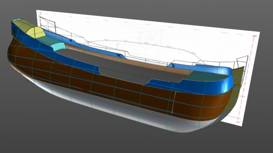
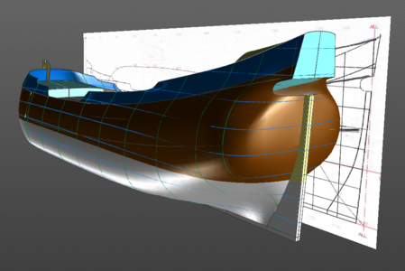
I used the model of Ab, which saved me hours and hours of drawing (Thx @Ab Hoving ) to reshape the hull to fit the drawing contours.
For this I imported and rescale the drawings into delftship.
Then you see that the shape of the ship is not completely following the drawings from the 3d scanning so the hull needs reshaping to fit the drawings.
See below the side view and top view showing Ab s design againt the Eriksson drawings. The decks are visible.
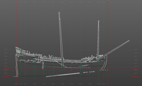
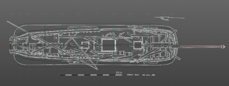
The next step is to fit the drawings Ab made towards the drawings from Eriksson which were made from the 3D scanning of the wreck.
That I will post next time as I am still working on this.
DELFTship
Ab Hoving provided me with his fluit models he made in Delftship and one of those was his interpretation of the ghost ship by using just the dimensions and witsens proportions.


I used the model of Ab, which saved me hours and hours of drawing (Thx @Ab Hoving ) to reshape the hull to fit the drawing contours.
For this I imported and rescale the drawings into delftship.
Then you see that the shape of the ship is not completely following the drawings from the 3d scanning so the hull needs reshaping to fit the drawings.
See below the side view and top view showing Ab s design againt the Eriksson drawings. The decks are visible.


The next step is to fit the drawings Ab made towards the drawings from Eriksson which were made from the 3D scanning of the wreck.
That I will post next time as I am still working on this.
Hi Heinrich,Good luck with the research. I f I were you I would regard Witsen and Van Yk as primary sources.
An actual documented/measured wreck will prevail the written source. For the none measured or documented items Witsen and Van Eijk wil come in. This will be the case for the depth of the hull as she is partly sunken in the sea bed.
- Joined
- Apr 20, 2020
- Messages
- 6,242
- Points
- 738

your research is im
your research is impressive. good luck my friend
Dear MaartenFor the use of the reconstruction I will use delftship. This is an excellent tool for creating your hull shape in 3D. You can freely download it here if you want to use it.
DELFTship
www.delftship.net
Ab Hoving provided me with his fluit models he made in Delftship and one of those was his interpretation of the ghost ship by using just the dimensions and witsens proportions.
View attachment 305519
View attachment 305520
I used the model of Ab, which saved me hours and hours of drawing (Thx @Ab Hoving ) to reshape the hull to fit the drawing contours.
For this I imported and rescale the drawings into delftship.
Then you see that the shape of the ship is not completely following the drawings from the 3d scanning so the hull needs reshaping to fit the drawings.
See below the side view and top view showing Ab s design againt the Eriksson drawings. The decks are visible.
View attachment 305521
View attachment 305522
The next step is to fit the drawings Ab made towards the drawings from Eriksson which were made from the 3D scanning of the wreck.
That I will post next time as I am still working on this.
your research is impressive. good luck my friend
G'day Maarten, you certainly know how to pick interesting subjects to build, I think that this one will be very interesting, a few year's back I was reading on the net about how they built them, it will be great to follow your build, but it might be a struggle to get a seat,I wont have anything useful to add but happy to watch and learn.
Best regards John,
Next step is to reshape the top of the ship.
There are no lines plans available so this is something I will prepare myself. Partly from the Eriksson drawings for the top part of the ship and with Witsen, Van Eijk and Ab Hoving for the bottom part of the ship.
Eriksson made a top view and side view drawing with a scale bar of the wreck so these two I use to reconstruct the shape of the top side of the ship.
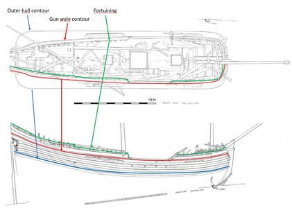
I have put the 2 2D drawings above each other and marked the same lines in top and side views with the same colours respectively red, green and blue.
The red line is the gun wale, the green line the top of the "Fortuining" which starts above the gun wale. And the blue line at the side view is the maximum width which is normally placed between the two lower wales.
If you combine the side and top view lines in a 3D program you get a 3D shape, in this way you can reshape the top part of the hull.
The main frame shape below the wales I determined by using Witsens formula's as provided by Ab Hoving.
Het Vlak
The bottom of the Fluyt was completely flat, in Dutch the bottom we call het vlak which translates to flat.
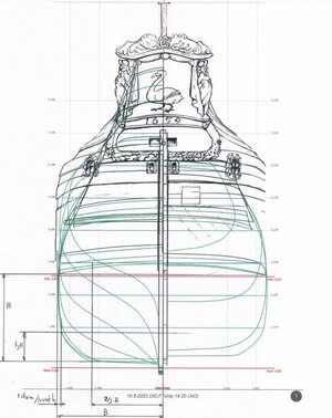
Het vlak was 2/3 of the width of the ship I reconstructed for half a ship but the proportion will be the same. In the drawing below I marked it with B and 2/3 B
De kim
Het vlak was 6 planks wide and these were next to each other in a straight line. After that 2 or 3 strokes of planks followed which shaped the curvature towards the side of the hull, these were called de kim. In shell first builds the first plank of the kim created a small knick in the hull at the junction with the plank of het vlak.
The height of the kim was up to 1/3 of the depth of the hull. The depth of the hull was measured from the top of the keel towards the top of the lower deck beams in the side of the hull. The depth of the hull was normally around 10% of the lenght between stem and stern. I marked the depth with H.
I drew a horizontal line at 1/3 of the depth.
The width at the kim was the total width minus 1 duim/10 feet length on each side. The Amsterdam duim was 1/11 of an Amsterdam foot which is 2,573936 centimeters. The Amsterdam foot was 0,2831 meter. My hull is 95 foot so my kim should be the width minus 9,5 duim which is total 24,5 cm less.
I drew a vertical line at this point. The crossing of these two lines determine the kim and my frame line should pass this crossing.
See below the shape I have drawn for the main frame.
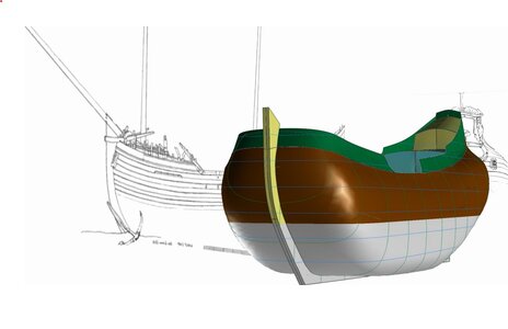
I have drawn the lines in Delftship and reshaped the hull untill it fullfilled all these parameters which resulted in this temporary hull.
Next I will discuss the "stuurlast" which means the vessel is deeper in the water at the stern.
There are no lines plans available so this is something I will prepare myself. Partly from the Eriksson drawings for the top part of the ship and with Witsen, Van Eijk and Ab Hoving for the bottom part of the ship.
Eriksson made a top view and side view drawing with a scale bar of the wreck so these two I use to reconstruct the shape of the top side of the ship.

I have put the 2 2D drawings above each other and marked the same lines in top and side views with the same colours respectively red, green and blue.
The red line is the gun wale, the green line the top of the "Fortuining" which starts above the gun wale. And the blue line at the side view is the maximum width which is normally placed between the two lower wales.
If you combine the side and top view lines in a 3D program you get a 3D shape, in this way you can reshape the top part of the hull.
The main frame shape below the wales I determined by using Witsens formula's as provided by Ab Hoving.
Het Vlak
The bottom of the Fluyt was completely flat, in Dutch the bottom we call het vlak which translates to flat.
Het vlak was 2/3 of the width of the ship I reconstructed for half a ship but the proportion will be the same. In the drawing below I marked it with B and 2/3 B
De kim
Het vlak was 6 planks wide and these were next to each other in a straight line. After that 2 or 3 strokes of planks followed which shaped the curvature towards the side of the hull, these were called de kim. In shell first builds the first plank of the kim created a small knick in the hull at the junction with the plank of het vlak.
The height of the kim was up to 1/3 of the depth of the hull. The depth of the hull was measured from the top of the keel towards the top of the lower deck beams in the side of the hull. The depth of the hull was normally around 10% of the lenght between stem and stern. I marked the depth with H.
I drew a horizontal line at 1/3 of the depth.
The width at the kim was the total width minus 1 duim/10 feet length on each side. The Amsterdam duim was 1/11 of an Amsterdam foot which is 2,573936 centimeters. The Amsterdam foot was 0,2831 meter. My hull is 95 foot so my kim should be the width minus 9,5 duim which is total 24,5 cm less.
I drew a vertical line at this point. The crossing of these two lines determine the kim and my frame line should pass this crossing.
See below the shape I have drawn for the main frame.

I have drawn the lines in Delftship and reshaped the hull untill it fullfilled all these parameters which resulted in this temporary hull.

Next I will discuss the "stuurlast" which means the vessel is deeper in the water at the stern.
Last edited:
As said she was the Jennifer Lopez of the shipsVery interesting. She is a portly little girl, heh? Lots of round curves. Assuming her flat bottom design was necessary, due to shallow home harbor waters? Wonder how that affected her sailing in open waters.
Thanks for sharing Maarten.
The Dutch harbour are shallow ports and that is the reason of the flat bottom which provides maximum cargo capacity at limited draft.
You would expect the sailing behaviour of these ships wouldn t be too bad as they were build over two centuries.
Hi Maarten.Next step is to reshape the top of the ship.
There are no lines plans available so this is something I will prepare myself. Partly from the Eriksson drawings for the top part of the ship and with Witsen, Van Eijk and Ab Hoving for the bottom part of the ship.
Thank you for sharing, all off it is very interesting. Very nice lines.
And good to see that Ab Hovings work is put to good use again.
- Joined
- Jan 9, 2020
- Messages
- 10,566
- Points
- 938

Fluyt ships were good sailing ships. Ships equipped for voyages to the East Indies featured the second hull layer against the infamous "Paalworm" and a galleon at the bow. De Reijger - one of the three ships in Jan van Riebeeck's voyage to the Cape in 1652 - was a fluyt.


