
-

SUBSCRIBE TO SHIPS IN SCALE TODAY!
The beloved Ships in Scale Magazine is back and charting a new course for 2026!
Discover new skills, new techniques, and new inspirations in every issue.
NOTE THAT OUR NEXT ISSUE WILL BE July/August 2026 -

Win a Free Custom Engraved Brass Coin!!!
As a way to introduce our brass coins to the community, we will raffle off a free coin during the month of August. Follow link ABOVE for instructions for entering.
You are using an out of date browser. It may not display this or other websites correctly.
You should upgrade or use an alternative browser.
You should upgrade or use an alternative browser.
A Dutch Fluyt in shell first, reconstructing the "Ghost ship" scale 1:36
- Thread starter Maarten
- Start date
- Watchers 77
-
- Tags
- dutch fluit

Hi Heinrich,Dear Maarten
Now this the type of research that I can spend hours reading. You are very fortunate in having such well-preserved wrecks to work from - with your through research, interpretational skills and computer literacy, I know that this these will be an expertly crafted set of plans - much better than what so called historians can come up with.
Glad you like it, I only have to disappoint you regarding drawings. Exept for the drawings I made in delftship regarding the hull shape I don't plan to make any other drawings.
My idea is to build as they did in the 17th century, this means working with proportions only. The only sketches I will make is when preparing the part itself and sketch directly on the wooden parts. I have already prepared a list of parts dimensions based on Witsens which Ab made for his book about the Tasman ships. I proportionally calculated these to a 95 foot fluyt as i am building.
The Delftship model and lines drawings I will use to check and control the shape of the hull during the build process.
The Tallinn Fluyt is measured roughly at 25 mtrs, see picture below. If you would measure over the stem stern this would be slightly more. If I use Amsterdam feet then this hull is 90 A-feet, being 90 x 0,2831 = 25,48 mtrs

- Joined
- Sep 3, 2021
- Messages
- 5,210
- Points
- 738

Wow, building without drawings, that's quite the challenge! Admittedly, I didn't have or made any drawings for the scratch build doors and hatches I made, but this is something else entirely. Add to the mix that IMHO this is a very complex hull shape... I'm definitely looking forward to your updates!Hi Heinrich,
Glad you like it, I only have to disappoint you regarding drawings. Exept for the drawings I made in delftship regarding the hull shape I don't plan to make any other drawings.
My idea is to build as they did in the 17th century, this means working with proportions only. The only sketches I will make is when preparing the part itself and sketch directly on the wooden parts. I have already prepared a list of parts dimensions based on Witsens which Ab made for his book about the Tasman ships. I proportionally calculated these to a 95 foot fluyt as i am building.
The Delftship model and lines drawings I will use to check and control the shape of the hull during the build process.
The Tallinn Fluyt is measured roughly at 25 mtrs, see picture below. If you would measure over the stem stern this would be slightly more. If I use Amsterdam feet then this hull is 90 A-feet, being 90 x 0,2831 = 25,48 mtrs
View attachment 351721
- Joined
- Jan 9, 2020
- Messages
- 10,733
- Points
- 938
I understand exactly what you are saying Maarten. It would be very interesting to see how Witsen's projections pan out in real life when you build the Fluyt "proportionally", as you say. Seeing that Witsen's "Aeloude en hedendaagsche scheeps-bouw en bestier" of the pinas is actually the only source of specifications that exist in the Netherlands, it is regularly (somewhat ad nauseam, in my opinion) quoted as the be-all and the end-all of Dutch shipbuilding practices in the 17th Century. However, this does not automatically mean it is correct - the final proof of the pudding can only be evaluated as you cook up this delectable dessert.
Another very interesting chapter, Maarten. Wonderful that they were able to make these underwater 3D scans.A Long time ago since I posted on this upcomming build, but I am still doing a lot of work behind the scenes.
Currently I am especially gathering a much data as I can get on period build wreck sites which let me already to some very interesting digital archives, museums etc.
I also found an additional Fluyt wreck in the Baltic which sank 2 nd Q of the 17th century near Tallinn Estonia.
This wreck I found via Sketch Fab, the Estonian heritage committee made a 3d model of the site on sketchfab, which you can find here.
You directly see this is a fluyt by the shape of the stern where the upper frames are creating a very strong tumble home which is so characteristic for the fluyt.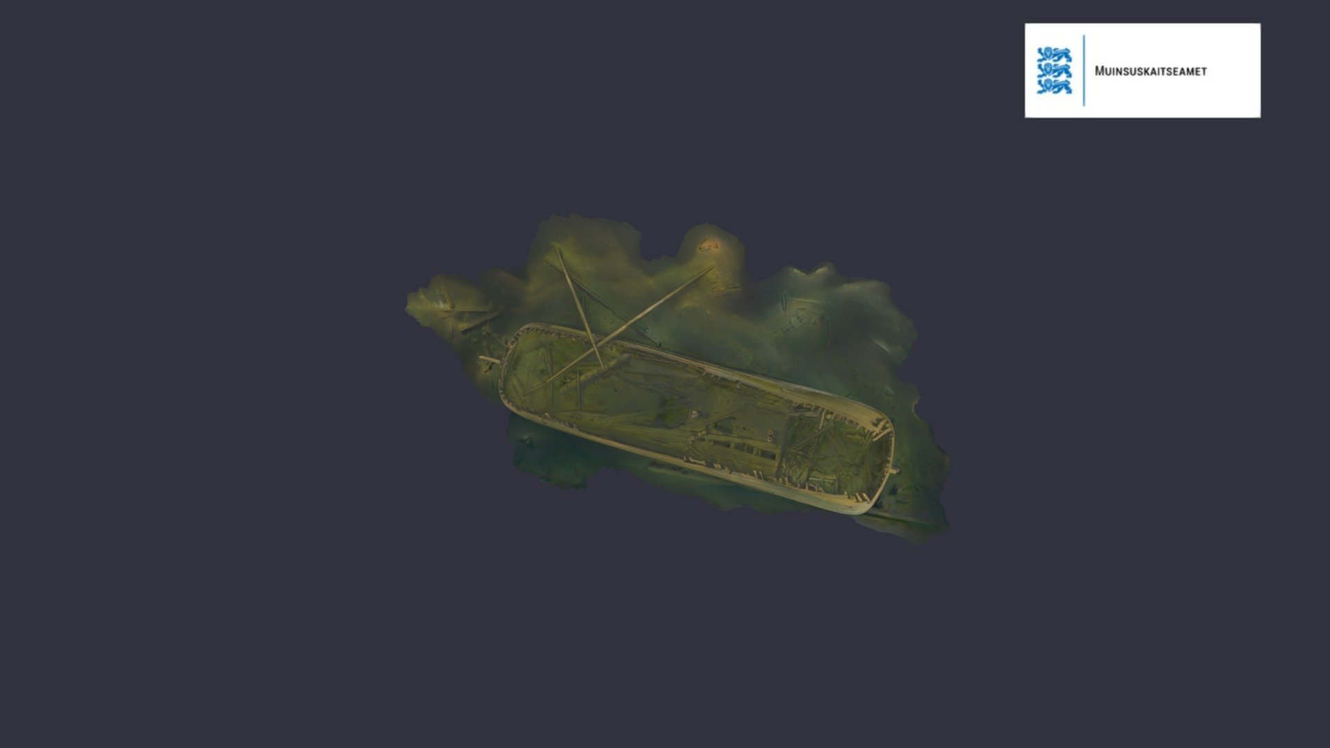
Barokiajastu purjeka vrakk/ 17th century wreck - 3D model by Muinsuskaitseamet
Laevavrakk asub Tallinnast u 20 km kaugusel Uusmadala ja Naissaare vahel 60 meetri sügavusel. See on üsna väheldaste mõõtmetega purjekas pikkusega umbes 25 meetrit, mis on seniajani säilinud praktiliselt puutumatuna. Vraki orienteeruvat uppumisaega aitavad määratleda vrakil asuvad nõud...sketchfab.com
What for me is very interesting about this wreck is again it preservation in combination with the upper part which fell of in time, this allows you to see the structure at a different level then in the other wreck and help you to determine the structure of the hull at different frame positions. The Ghost ship (swan) wrekc is preserved nearly complete including half deck and fore castle deck. This wreck is preserved up to the main deck so you can see below the fore castle deck and look into the great cabin. You can clearly see the bow and stern cant frames. You can even see from these frames that these are following the line of the outside planking which point to shell first building, but I will come back on that later. Typical Dutch shape of fluyt with blunt bow and stern.
View attachment 351485
Different wrecks in different stages of preservation show all very valuable information for my reconstruction.
First we have Anna Maria in Sweden.
Anna Maria was exploded after her crew left her in port while visiting the local tavern and kept the fireplace onboard burning, OEPS.
View attachment 351488
Luckily for me I can now see the frame construction towards the keel in the stern section.
View attachment 351490
You can see here that the frame member are not connected to each other but only to the outside planking. You can see the frame structure clearly.
View attachment 351487
I can measure the height of the hold to the orlopdeck and even the space between orlop and main deck, and use the ratios for my reconstruction and compare them to the data Witsen provides.
View attachment 351489
On the bow you see the bow frames ad there position clearly following the shape of the outside planking in their placement. To me this means the shape of the planking was there before the frames were placed. These frame do not follow the same line as the stem, they are not perpendicular to the water line but but placed to create and even spread in the pre determined shape, read shell first.
The Tallin wreck is a s said more complete, we move from the hold and orlop deck to the main deck, but the half deck and fore castle are missing.
View attachment 351493
The bow of this ship show exactly the same construction around the hawser holes as the ship I am going to build, and these part seemed to be carved. The top wale is showing a rounded shape.
View attachment 351494
View attachment 351498
The frames in the stern and bow show the same positioning as in the Anna Maria bow following the shape of the planking which I marked below.
The stern section below.
View attachment 351491
The bow section
View attachment 351492
The blunt bow and stern are again comparable to the Anna Maria and the Ghost Ship (Swan).
The stern with its default cargo doors in the rear used for loading planks and tree tree trunks into the hold and on the orlop, which went through the great cabin. The smaller openings above are the cabin windows.
View attachment 351497
It look like this ship has a second layer of planks as ther eis nearly no difference between the lower wale and the lower hull planking below the wale. I have read this is also the case for the Ghost Ship. In theory yu wont expect it for baltic traders as they are not prown to the famous ship worm. I have to dig into thos more to get an explanation, maybe the strenght of the ship in ice would be a reason.
Next time I will show more interesting construction details and other sources of research material.
Regards, Peter
Thx gents for still following my investigative blog while there is still no saw dust.
Today I am looking into planking patterns. We know Dutch build ships are build getting the most out of the material available, which results in different plank widths and lenghts, no standardization.
Sofar I thought that for a shell first fluyt build the hull planks as of the bilge (kimmen) up to the wales should more or less follow the shape if the lower wale, like in the build below.

You can see the same construction in the wonderfull fluyt Zeehaen that @Ab Hoving build.

As I have some underwater 3 d models to study I digged into their planking and I see another pattern appearing.
First the select number of photo s of the Ghost ship. I have traced the planking with lines.
In the stern you clearly see a diagonal pattern, not following the lower wale but with there ends joining to the lower wale. You can see the lower wale, the lower hull planking, the great cabin hatch and the stern post.

Maritime archeologist Niklas Eriksson mentioned in one of his publications that the Ghost ship had a second planking, which was common for Dutch ships going to tropical waters.
I thought maybe that is the case here also, a second planking to increase the ships strenght for sailing in the Baltic ice. This second planking would explain the diagonal planking as the second layer is following a different pattern.
But looking further at the great cabin hatch you don t see any second planking layer. With a second planking layer I would also expect that the lower wale would not protrude from the lower hull planking and the wale is protruding equally compared to the lower planking as to the planking between the wales. To me this is a sign there is no second planking present.
Lower in the stern at the SB side there is a cargo hatch which is closed up with planks. This was common on the wood haulers which had a hatch like this just above the waterline. Easy to load tree logs into the lower hold.
When going to sea it was closed with planks, nailed and caulked.
Here you see the same diagonal planking towards the stern post.

Looking at the bow.
The top part of the picture shows the lower wale and below it the hull planking not following but jointing towards the wale.

In front of it is the anchor and anchor stock, and toxshow you where we are I have added a piece of the archeologic drawing.
So the ghost ship has diagonal planking ending towards the lower wale in the bow and the stern.
Lets check Anna Maria, a late 17th century Amsterdam build fluyt.

Exactly the same. The lower wale is partly gone and you can see the planking diagonally ending towards the wale. Secondly you can see single planking as were the plank parts are gone you directly see the frames.
Unfortunately the stern of the Anna Maria is no more after she blew up in the early 18th century and sank.
The third fluyt is the one which is before the coast of Tallinn. And yes again clearly diagonal planking. I think I spot a trend here.

I will do some additional research in non fluyt wrecks to see if I find comparable constructions.
I clearly see the same on this contempory drawing of a shipyard. Towards the bow you see diagonal planking reaching towards the cent line which is the line between the two lower wales which are not present yet.

In principle a fluyt has a bow shaped stern, so this should be comparable.
If this is the conclusion then I have to rethink my building methode. But thats for later, comming closer and closer to first dust.") .
.
Today I am looking into planking patterns. We know Dutch build ships are build getting the most out of the material available, which results in different plank widths and lenghts, no standardization.
Sofar I thought that for a shell first fluyt build the hull planks as of the bilge (kimmen) up to the wales should more or less follow the shape if the lower wale, like in the build below.
You can see the same construction in the wonderfull fluyt Zeehaen that @Ab Hoving build.
As I have some underwater 3 d models to study I digged into their planking and I see another pattern appearing.
First the select number of photo s of the Ghost ship. I have traced the planking with lines.
In the stern you clearly see a diagonal pattern, not following the lower wale but with there ends joining to the lower wale. You can see the lower wale, the lower hull planking, the great cabin hatch and the stern post.
Maritime archeologist Niklas Eriksson mentioned in one of his publications that the Ghost ship had a second planking, which was common for Dutch ships going to tropical waters.
I thought maybe that is the case here also, a second planking to increase the ships strenght for sailing in the Baltic ice. This second planking would explain the diagonal planking as the second layer is following a different pattern.
But looking further at the great cabin hatch you don t see any second planking layer. With a second planking layer I would also expect that the lower wale would not protrude from the lower hull planking and the wale is protruding equally compared to the lower planking as to the planking between the wales. To me this is a sign there is no second planking present.
Lower in the stern at the SB side there is a cargo hatch which is closed up with planks. This was common on the wood haulers which had a hatch like this just above the waterline. Easy to load tree logs into the lower hold.
When going to sea it was closed with planks, nailed and caulked.
Here you see the same diagonal planking towards the stern post.
Looking at the bow.
The top part of the picture shows the lower wale and below it the hull planking not following but jointing towards the wale.
In front of it is the anchor and anchor stock, and toxshow you where we are I have added a piece of the archeologic drawing.
So the ghost ship has diagonal planking ending towards the lower wale in the bow and the stern.
Lets check Anna Maria, a late 17th century Amsterdam build fluyt.
Exactly the same. The lower wale is partly gone and you can see the planking diagonally ending towards the wale. Secondly you can see single planking as were the plank parts are gone you directly see the frames.
Unfortunately the stern of the Anna Maria is no more after she blew up in the early 18th century and sank.
The third fluyt is the one which is before the coast of Tallinn. And yes again clearly diagonal planking. I think I spot a trend here.
I will do some additional research in non fluyt wrecks to see if I find comparable constructions.
I clearly see the same on this contempory drawing of a shipyard. Towards the bow you see diagonal planking reaching towards the cent line which is the line between the two lower wales which are not present yet.
In principle a fluyt has a bow shaped stern, so this should be comparable.
If this is the conclusion then I have to rethink my building methode. But thats for later, comming closer and closer to first dust.
.
Last edited:
- Joined
- Aug 8, 2019
- Messages
- 5,767
- Points
- 738
Nice info. It is this info and the info of Yk and Witse to rethink the building method for these ships. It is not the same like an French or English ship. Where you can make a mold where you put in the frames. The frames where not all the same kind. It are the whales and the stock of wood what decide the form and build of the ship. Like the discription in the books. That's why I started with the keel and see how I go further from there.
Maarten let start the dust
Maarten let start the dust
Looks like an interesting read.Hello Maarten,
Maybe the book " Het model van het Fregat "Geelvinck' " can help you with the technic of building shell first.
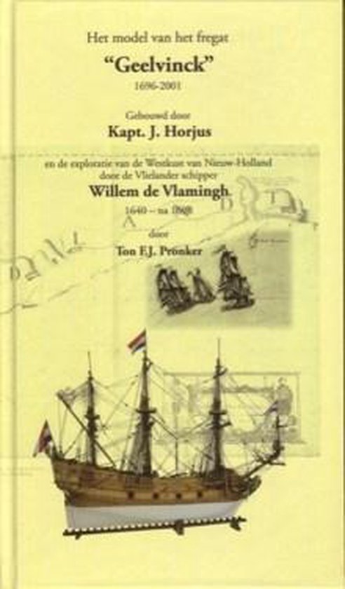
It's about another type of vessel but it shows how building shell first looks like.
Good luck
Hans Peters
Hoorn
Hi Hans,Hello Maarten,
Maybe the book " Het model van het Fregat "Geelvinck' " can help you with the technic of building shell first.
It's about another type of vessel but it shows how building shell first looks like.
Good luck
Hans Peters
Hoorn
Many thanks for the tip.
I have already investigated a lot about shell first building but hope it can add something.
I ordered a used one via boekwinkeltjes.nl.
Good morning, Maarten.
Yesterday, while browsing my books in the Russian Language, I came across some photos of Fluyit. This is the drawing by Villem Van Velde from the Museum of History Seamanship in Amsterdam. You may find them usfull.


Yesterday, while browsing my books in the Russian Language, I came across some photos of Fluyit. This is the drawing by Villem Van Velde from the Museum of History Seamanship in Amsterdam. You may find them usfull.
Hi Jim,Good morning, Maarten.
Yesterday, while browsing my books in the Russian Language, I came across some photos of Fluyit. This is the drawing by Villem Van Velde from the Museum of History Seamanship in Amsterdam. You may find them usfull.
View attachment 359595
View attachment 359596
View attachment 359597
Many thx for the info. The Van de Velde drawing I am familiar with. It is a heavy armed Fluyt named "Goede Herder" or in English the good Shepherd.
Last Sunday I paid a brief visit to the Batavia yard and museum. There they have a 17th century wreck of an inland waterway fishtrader called a ventjager which was found when creating the new land of Flevoland which was still sea bottom at the beginning of 1900s.
I was mainly interested in the lower part of the hull, meaning the planking of the floor and bilge and if this pattern could be used for the Fluyt.
Here you see the ps side of the ship which is very well preserved as this side was covered with mud, the SB side is gone creating a perfect half ship section.

On the bow you can perfectly see that the three planks creating the floor are parallel to the keel.
The planks creating the bilge are enclosing the floor planks and end at the stem.

The same in the stern

In this ship the top planks are again parallel to the wale as the bilge planks are spliced. This I don t see this in the investigated fluyt wrecks where the top planks are ending against the wale and are not running parallel with it in the stem and stern sections.

So I got a clear picture how to plank the floor and bilge of the fluyt.
For the rest I got some inspiration about the hull. My fluyt will be build as a real work horse with plenty of patina. For this I will create section of repairs in the planking. I have seen this on multiple wrecks but this one really has a lot of contemporary repairs. See below some of these.


Also some ideas about interior decoration. This ship cabin is really well preserved.


At last the internal framing shows you a shell first build ship, again no interconnecting frame members, only connected to the planking.

And the floor and frames in the bow.

I was mainly interested in the lower part of the hull, meaning the planking of the floor and bilge and if this pattern could be used for the Fluyt.
Here you see the ps side of the ship which is very well preserved as this side was covered with mud, the SB side is gone creating a perfect half ship section.
On the bow you can perfectly see that the three planks creating the floor are parallel to the keel.
The planks creating the bilge are enclosing the floor planks and end at the stem.
The same in the stern
In this ship the top planks are again parallel to the wale as the bilge planks are spliced. This I don t see this in the investigated fluyt wrecks where the top planks are ending against the wale and are not running parallel with it in the stem and stern sections.
So I got a clear picture how to plank the floor and bilge of the fluyt.
For the rest I got some inspiration about the hull. My fluyt will be build as a real work horse with plenty of patina. For this I will create section of repairs in the planking. I have seen this on multiple wrecks but this one really has a lot of contemporary repairs. See below some of these.
Also some ideas about interior decoration. This ship cabin is really well preserved.
At last the internal framing shows you a shell first build ship, again no interconnecting frame members, only connected to the planking.
And the floor and frames in the bow.
Last edited:
- Joined
- Aug 8, 2019
- Messages
- 5,767
- Points
- 738
Informative pictures, I studied them and see a lot of things that are useable, also for my build. The irons on the keel for the rudder are not horizontal but are perpendicular to the back of the keel. Also the bilge futtocks shown in the pictures learn us a lot about the building methods of the Dutch. It isn't so exact as on the English/French builds. I learned now that the futtocks will be different in width. Thanks for sharing Maarten
And we work sooo hard to perfect every little detail on our ships and boats!
Thats due too the way of building. In shell first the individual frame parts are not joined to each other which means the don't have to fit to each other which makes the building process much more simple. Secondly every piece of frame timber could be tailor made to fit in the shell created. A 30 mtr Fluyt on a Ducth yard was build in just a few months with a yard crew of 20-30 people. You can't compare that with an English navy yard where 2-3 years for a ship were needed with a multiple number of yard personel. Offcourse a navy vessel was also much more complicated then a regular merchant ship.And we work sooo hard to perfect every little detail on our ships and boats!
BTW a large part of the French war fleet was also build in Holland especially in the first half of the 17th century.
Maybe I should build Dutch ships from now on. I can just throw things together and say that’s the way it’s supposed to be.Thats due too the way of building. In shell first the individual frame parts are not joined to each other which means the don't have to fit to each other which makes the building process much more simple. Secondly every piece of frame timber could be tailor made to fit in the shell created. A 30 mtr Fluyt on a Ducth yard was build in just a few months with a yard crew of 20-30 people. You can't compare that with an English navy yard where 2-3 years for a ship were needed with a multiple number of yard personel. Offcourse a navy vessel was also much more complicated then a regular merchant ship.
BTW a large part of the French war fleet was also build in Holland especially in the first half of the 17th century.


Thank you for sharing Maarten, wonderful pictures and very informative.Last Sunday I paid a brief visit to the Batavia yard and museum. There they have a 17th century wreck of an inland waterway fishtrader called a ventjager which was found when creating the new land of Flevoland which was still sea bottom at the beginning of 1900s.
I was mainly interested in the lower part of the hull, meaning the planking of the floor and bilge and if this pattern could be used for the Fluyt.
Here you see the ps side of the ship which is very well preserved as this side was covered with mud, the SB side is gone creating a perfect half ship section.
View attachment 361821
On the bow you can perfectly see that the three planks creating the floor are parallel to the keel.
The planks creating the bilge are enclosing the floor planks and end at the stem.
View attachment 361822
The same in the stern
View attachment 361823
In this ship the top planks are again parallel to the wale as the bilge planks are spliced. This I don t see this in the investigated fluyt wrecks where the top planks are ending against the wale and are not running parallel with it in the stem and stern sections.
View attachment 361824
So I got a clear picture how to plank the floor and bilge of the fluyt.
For the rest I got some inspiration about the hull. My fluyt will be build as a real work horse with plenty of patina. For this I will create section of repairs in the planking. I have seen this on multiple wrecks but this one really has a lot of contemporary repairs. See below some of these.
View attachment 361825
View attachment 361826
View attachment 361827
Also some ideas about interior decoration. This ship cabin is really well preserved.
View attachment 361828
View attachment 361829
At last the internal framing shows you a shell first build ship, again no interconnecting frame members, only connected to the planking.
View attachment 361831
And the floor and frames in the bow.
View attachment 361830
- Joined
- Sep 3, 2021
- Messages
- 5,210
- Points
- 738
I wouldn't say it was that easy:Maybe I should build Dutch ships from now on. I can just throw things together and say that’s the way it’s supposed to be.
"A preventive measure to save wood was to grow the trees in a pre-wanted form. This aimed to get the necessary wood available in its most advantageous and strongest forms, so with little waste. This was especially the case for "krommers", which were the hardest to find and most expensive. In order for certain "krommers" to grow, young trees were bent or pruned in the desired shape. This was called bunched wood." Source https://vaartips.nl/hout.htm
Using these pre-formed elements meant that it wouldn't all fit perfectly, but the builders were using what was available and what best fitted the required function.
I would really like to see a modeler building a model of a fluyt, or something similar, using the old Dutch ways.
Pre-forms sought after:

Example

Ow that really takes advanced planning !