-

Win a Free Custom Engraved Brass Coin!!!
As a way to introduce our brass coins to the community, we will raffle off a free coin during the month of August. Follow link ABOVE for instructions for entering.
-

PRE-ORDER SHIPS IN SCALE TODAY!
The beloved Ships in Scale Magazine is back and charting a new course for 2026!
Discover new skills, new techniques, and new inspirations in every issue.
NOTE THAT OUR FIRST ISSUE WILL BE JAN/FEB 2026
You are using an out of date browser. It may not display this or other websites correctly.
You should upgrade or use an alternative browser.
You should upgrade or use an alternative browser.
A Dutch Fluyt in shell first, reconstructing the "Ghost ship" scale 1:36
- Thread starter Maarten
- Start date
- Watchers 74
-
- Tags
- dutch fluit
- Joined
- Apr 20, 2020
- Messages
- 6,257
- Points
- 738

Fantastic work, I appreciate your work methods and the willingness to share with us and thus you help us to improve our abilities.I will be there, hope to see you in September.
Today I didn t had much time but could spend two hours on preparing stem and stern.
For these I used my waterlines drawing.
The thickness of the stem and stern is according Witsen 1 duim (amsterdam inch) per 1/10 foot of ships length. For my ship this is ((95/10) × (Amsterdam foot/11))/36 = 6,8 mm.
Comparing to the archological drawings this correct.
The width of stem and stern I determined by adding the thickness of the planking twice. Compared to the top view of the archeological drawings this was correct.
Based on this I have drawn the stem outlines.
I also drew the keel stem connection, in 17th century Dutch called the kinnebak.
View attachment 370824
By spreading graphite powerder on the rear of the drawing I tranfered it to the 6,8 mm billet by tracing it with a pencil.
View attachment 370825
View attachment 370826
View attachment 370827
After cutting it on the small proxxon band saw I check it on the drawing.
View attachment 370828
The stern post was drawn in the same way.
After cutting both with the small proxxon band saw I have the outlines of the hull.
View attachment 370829
Next time I will double check if stem and stern post can be of one pieces. In principle for this size of ship it could be, but I will double check with the wreck data I have.
The keel I will split in two pieces with a joint before the main mast at +/-1/3 of the keel lenght
Next time preparing the keel and stem and stern joints.

Hi Stephan, I am still looking into this. I have made the complete part as it is easier to shape the complete part. If neede I will remove a small part of it and fit in the new piece.You make the stem out of 1 piece of wood?
As this is a smaller ship these parts could be made out of one part, but larger wood parts are more valuable so the questions is if they did it like this.
The wreck of the Fluyt Anna Maria looks like two parts on the stem and stern post. However Anna Maria is much bigger.
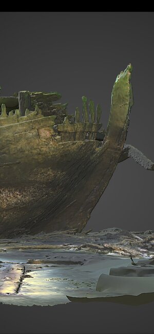
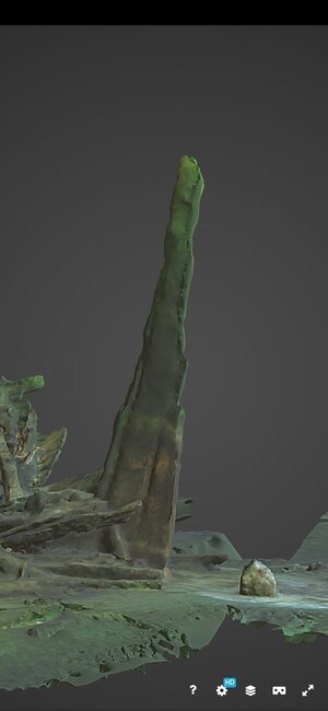
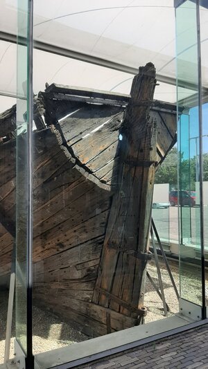
On the Den Helder Pinas the stern post is build of it looks like 3 parts, the stem post seems to be one piece.
- Joined
- Aug 8, 2019
- Messages
- 5,585
- Points
- 738

It depends on the thickness of the tree and if they can make it in one piece. I work with woodpieces that have a max. width of 28 mm so I had to splice it up.The wreck of the Fluyt Anna Maria looks like two parts on the stem and stern post. However Anna Maria is much bigger.
Yes these where made of a lot of parts, I was thinking about the drawings of Blom or Dik where there was a details drawing. It could also be in Abel Tasman ships where I found. I dive into it too find where.On the Den Helder Pinas the stern post is build of it looks like 3 parts, the stem post seems to be one piece.
One tip, make the keel of 1 piece and make fake joints. Don't cut him, building this way is a lot of stress on the keel clamping things.
Edit there is a nice picture of a stern in Ab's books
And also in the drawings of Blom
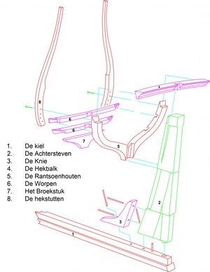
How I made that part, inspire on Blom
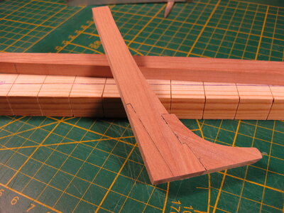
Edit:
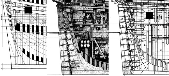
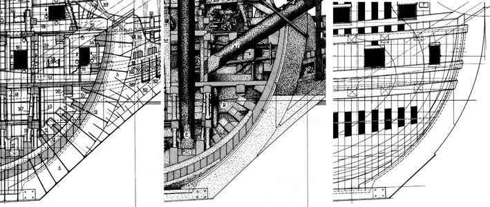
Last edited:
Based on the wreck data and the witsen drawings I decided to split my stern post in three parts.
First drawing a line to create the biggest part curved with more or less equal width.
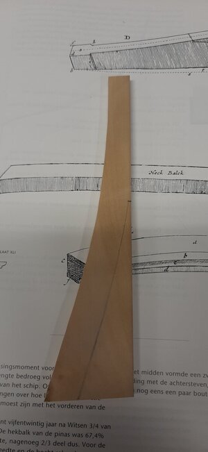
Then the proxxon band saw can do its job.
The part remove can t be reused and two new filler pieces are made to properly fit in.
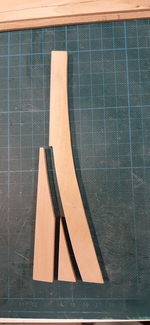
Dry fitting the assembly.
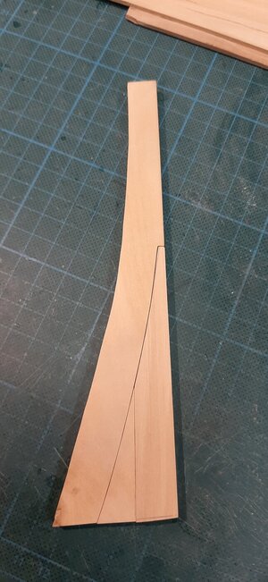
I glue these parts with brown coloured pva to simulate Stockholmer tar caulking.
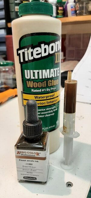
See below the black vs the braun pva.
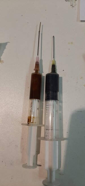
The brown pva used to glue the parts together on a glass plate.
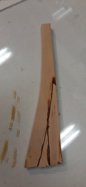
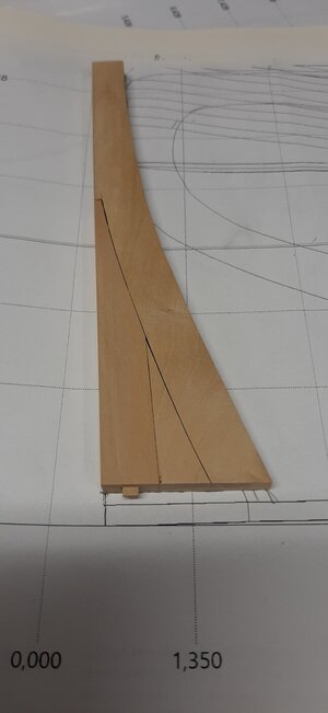
After sanding.
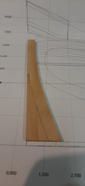
At last I add the wooden dowel to fit into the keel during assembly.
The keel I make of two parts, a long and a short part to avoid the main mast step will rest on the joint.
The small part will be on the aft side.
I have made the cut in the keel and did not make a simulation joint as there was a week spot in my keel which I now removed.
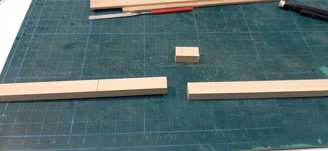
The keel joint is 5 times the keel width according to Witsen.
I cut the keel joints with the Proxxon band saw and finished them with a miniature diamond file by hand.
Again glued with brown pva on top of a glass plate to keep everyting alligned.
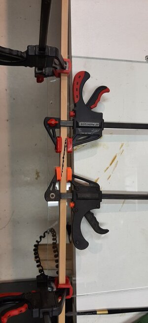
Next time finishing the keel and creating the box joint for the stem in Dutch the kinnebak.
First drawing a line to create the biggest part curved with more or less equal width.

Then the proxxon band saw can do its job.
The part remove can t be reused and two new filler pieces are made to properly fit in.

Dry fitting the assembly.

I glue these parts with brown coloured pva to simulate Stockholmer tar caulking.

See below the black vs the braun pva.

The brown pva used to glue the parts together on a glass plate.

After sanding.

At last I add the wooden dowel to fit into the keel during assembly.

The keel I make of two parts, a long and a short part to avoid the main mast step will rest on the joint.
The small part will be on the aft side.
I have made the cut in the keel and did not make a simulation joint as there was a week spot in my keel which I now removed.

The keel joint is 5 times the keel width according to Witsen.
I cut the keel joints with the Proxxon band saw and finished them with a miniature diamond file by hand.
Again glued with brown pva on top of a glass plate to keep everyting alligned.

Next time finishing the keel and creating the box joint for the stem in Dutch the kinnebak.
Maarten, I love your band saw, your work shop and your attention to detail. The photo of the Den Helder Pinas is amazing also. We are all learning so much! Magic Mike
A straight forward start, Maarten. Nice you are mentioning the Stockholmer Tar. A deja-vu. A long time ago we used that on the windmill to 'tar' some wooden parts. Now banned for a long time to use. And no modern means that can now serve as a good replacement. But your alternative looks very natural.Based on the wreck data and the witsen drawings I decided to split my stern post in three parts.
First drawing a line to create the biggest part curved with more or less equal width.
View attachment 370940
Then the proxxon band saw can do its job.
The part remove can t be reused and two new filler pieces are made to properly fit in.
View attachment 370941
Dry fitting the assembly.
View attachment 370942
I glue these parts with brown coloured pva to simulate Stockholmer tar caulking.
View attachment 370943
See below the black vs the braun pva.
View attachment 370945
The brown pva used to glue the parts together on a glass plate.
View attachment 370944
After sanding.
View attachment 370947
At last I add the wooden dowel to fit into the keel during assembly.
View attachment 370946
The keel I make of two parts, a long and a short part to avoid the main mast step will rest on the joint.
The small part will be on the aft side.
I have made the cut in the keel and did not make a simulation joint as there was a week spot in my keel which I now removed.
View attachment 370948
The keel joint is 5 times the keel width according to Witsen.
I cut the keel joints with the Proxxon band saw and finished them with a miniature diamond file by hand.
Again glued with brown pva on top of a glass plate to keep everyting alligned.
View attachment 370949
Next time finishing the keel and creating the box joint for the stem in Dutch the kinnebak.
Regards, Peter
Hi Mike thx for the comments and if you are interested in the Pinas which is called wreck E81, you can find a lot of data here. The actual shop was named Samuel and sunk at the end of the 17th century. She was found in the 1960's in a field, this as this part of the Netherlands is reclaimed land now where it was still the sea bottom untill 1924.Maarten, I love your band saw, your work shop and your attention to detail. The photo of the Den Helder Pinas is amazing also. We are all learning so much! Magic Mike
Bekijk alle beelden van:
Hi Peter,A straight forward start, Maarten. Nice you are mentioning the Stockholmer Tar. A deja-vu. A long time ago we used that on the windmill to 'tar' some wooden parts. Now banned for a long time to use. And no modern means that can now serve as a good replacement. But your alternative looks very natural.
Regards, Peter
Stockholmer tar is still available, I have ran some test of tarring ropes with it and it works, you have to add some siccative and turpentine to it otherwise it will never dry.
Your ropes realy get that authentic shipyard smell but when you are sitting the whole day in that smell you wil certainly get a headache.
The stem post is connected to the keel with a wood joint. Witsen is describing the kinnebak joint for the Pinas build he describes in his book.
On the Den Helder pinas, called E81 or most probably the ship Samuel that sunk in 1662, there is a similar stem post joint which you can see in the archeological drawing below.
The Samuel is from the same time and size as my fluyt build, Samuel was also shell first build for which proof has been found in the planking.
For me this can be the reason to choose the same type of joint for my stem post.
Witsen
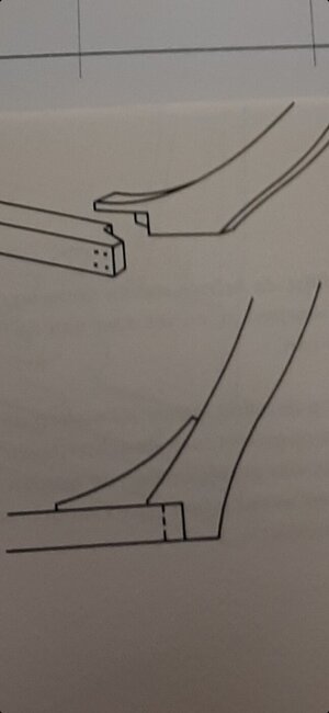
And the Samuel which seems to be a slightly simplified version.
![[MA]T-133455.jpg [MA]T-133455.jpg](https://shipsofscale.com/sosforums/data/attachments/355/355122-8b77dd99c3392dca3327506facd73dd0.jpg?hash=i3fdmcM5Lc)
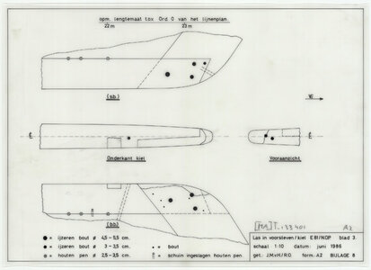
On the Den Helder pinas, called E81 or most probably the ship Samuel that sunk in 1662, there is a similar stem post joint which you can see in the archeological drawing below.
The Samuel is from the same time and size as my fluyt build, Samuel was also shell first build for which proof has been found in the planking.
For me this can be the reason to choose the same type of joint for my stem post.
Witsen

And the Samuel which seems to be a slightly simplified version.
![[MA]T-133455.jpg [MA]T-133455.jpg](https://shipsofscale.com/sosforums/data/attachments/355/355122-8b77dd99c3392dca3327506facd73dd0.jpg?hash=i3fdmcM5Lc)

Last edited:
The data of the Samuel is also interesting for my keel joint.
This joint is bolted with bolts, tree nails and iron nails. See some of the keel joint archeological drawings below.
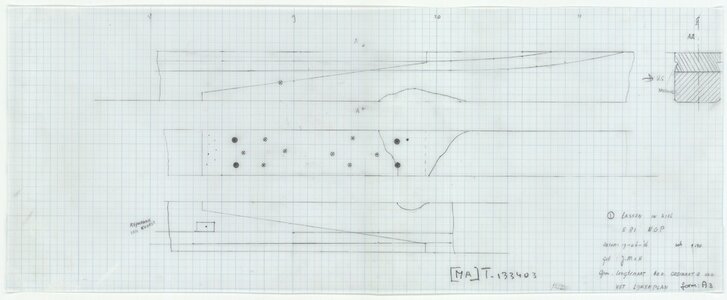
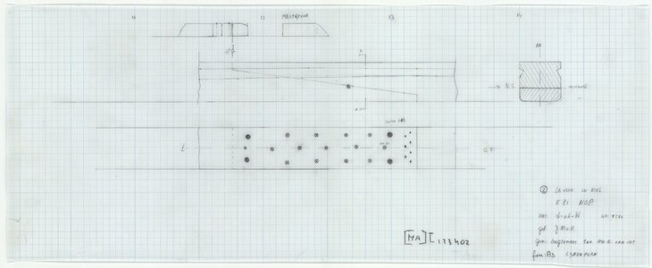
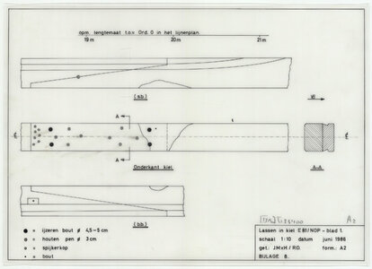
The big black dots are bolts, the white circles are tree nails and the small black dots are nails.
You can also see the shape of the rabbet in the keel.
This joint is bolted with bolts, tree nails and iron nails. See some of the keel joint archeological drawings below.


The big black dots are bolts, the white circles are tree nails and the small black dots are nails.
You can also see the shape of the rabbet in the keel.
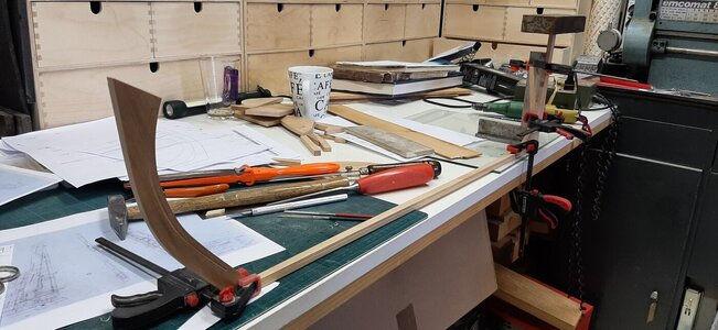
While working on the stem I found a strange mismatch in my water line drawings compared to the scale printed archeological drawings.
My waterline drawing printed in 1:36 scale showed a different lenght to width ratio of the hull. 4,2 instead of 3,8.
After a lot of seatching I found out that the import of the archeological drawings into my 3 d drawing program changed the ratio of the drawings meaning my 3d model was to small. Also the stem post was at the wrong angle and should be steaper.
To solve this I have corrected the ratio on the waterline drawings and made a new stempost.
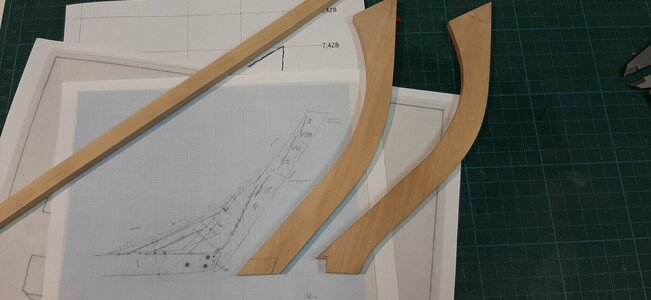
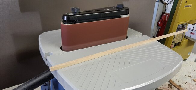
After this correction I could finally cut the keel to its correct length followed by sanding it into shape. The keel is tapered in width from the centre frame towards fwd and aft from 10,2 mm centre to 6.8 mm fwd and aft.
The band sander comes in handy here.
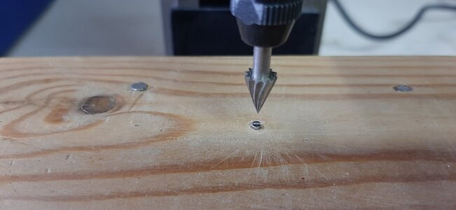
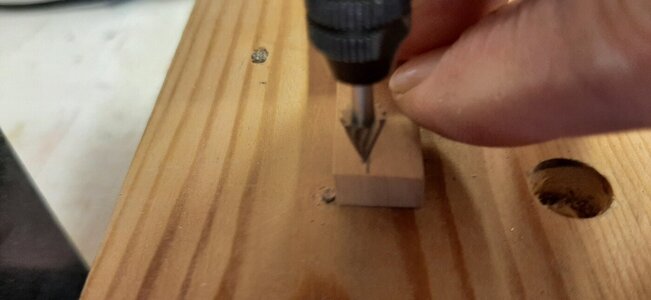
I mill a rabbet line into the parts for cutting the rabbet later in the proces.
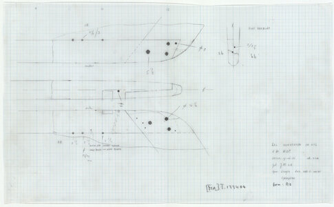
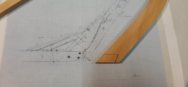
The joint of the stem post and keel I copy from the Den Helder Pinas Samuel which is of the same age and size as my build.
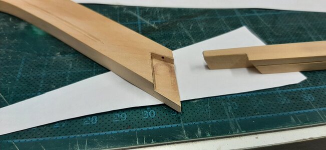
At the stern I have made the knee to support the stern post. For this I used Ab Hovings drawing of the flute Zeehaen. It is a perfect fit
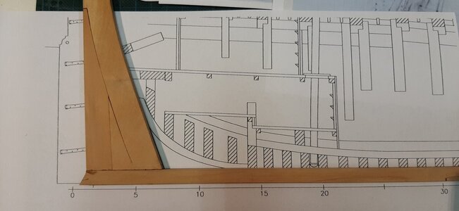
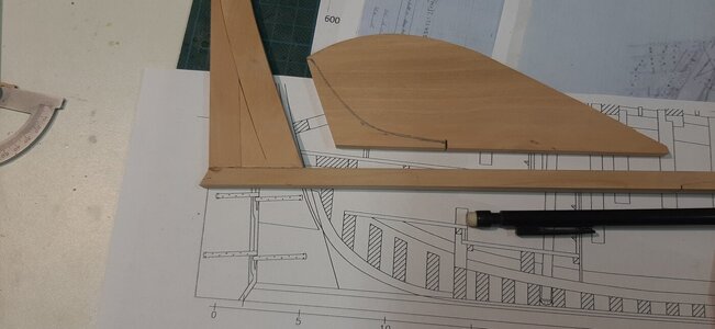
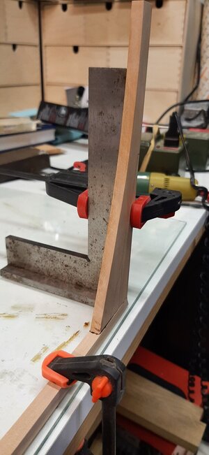
Finally glueing together.
My waterline drawing printed in 1:36 scale showed a different lenght to width ratio of the hull. 4,2 instead of 3,8.
After a lot of seatching I found out that the import of the archeological drawings into my 3 d drawing program changed the ratio of the drawings meaning my 3d model was to small. Also the stem post was at the wrong angle and should be steaper.
To solve this I have corrected the ratio on the waterline drawings and made a new stempost.

After this correction I could finally cut the keel to its correct length followed by sanding it into shape. The keel is tapered in width from the centre frame towards fwd and aft from 10,2 mm centre to 6.8 mm fwd and aft.
The band sander comes in handy here.

I mill a rabbet line into the parts for cutting the rabbet later in the proces.


The joint of the stem post and keel I copy from the Den Helder Pinas Samuel which is of the same age and size as my build.


At the stern I have made the knee to support the stern post. For this I used Ab Hovings drawing of the flute Zeehaen. It is a perfect fit


Finally glueing together.


While the glue on the keel, stem and stern dries work on the yard floor continues.
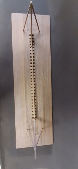
I prepare a 17th century yard. The keel is stacked on blocks of oak.
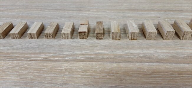
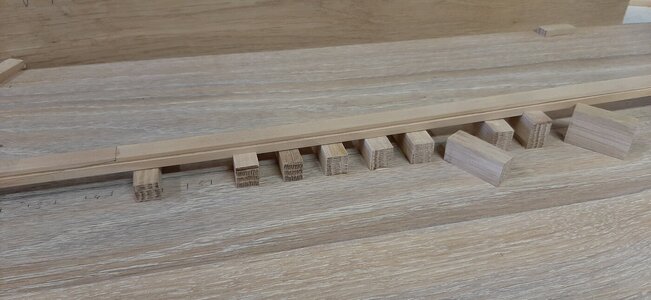
On Dutch yards the keel was stacked sagging, curved downward approximate 1/2 the thicknes of the keel. This was done as the bouyancy in the centre of the hull is higher and the keel would be straight while the ship was in the water.
Secondly a Dutch ship had "stuurlast" which means she is deeper in the water at the stern.
This stuurlast I have already set up in my blocks.
I set up the keel on 5 blocks, the rest is filled in when the keel is positioned. The keel is locked in place by adding small board clamping the keel snug fit.
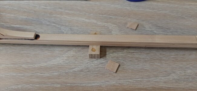
The result of all of this is every block is different in height and tailor made.
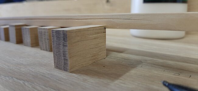
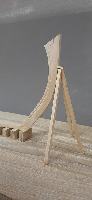
At stem and stern post a tripod of beams is setup to support the stem and stern post.
The yard floor is finished.
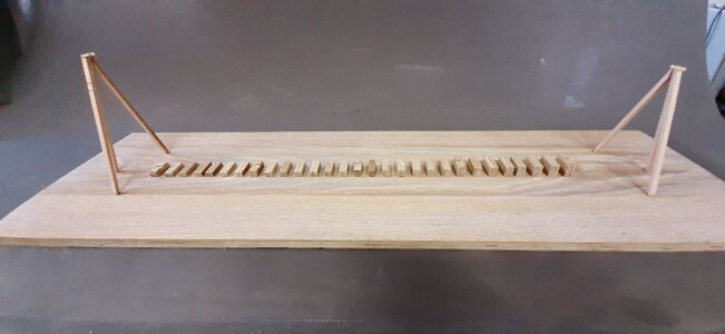
The keel is placed on the blocks.
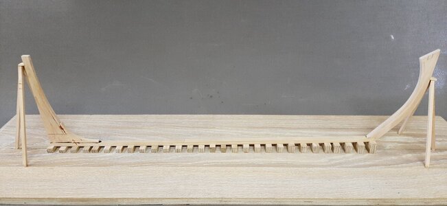
I have made a clamp around the stem and stern instead of nailing the wooden poles directly in the stem and stern post. This as I want to be able to remove it easily.
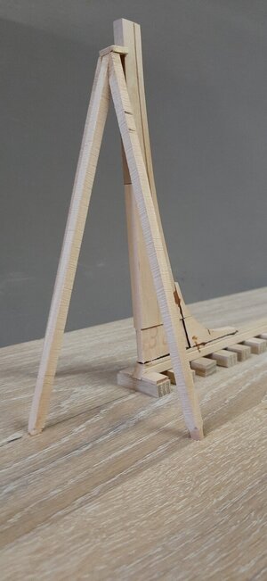
Here you can clearly see the sagging of the keel.
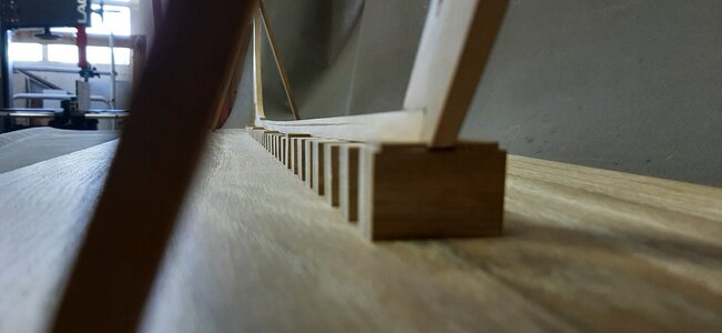
And the top view.
Next time a knee for the stem post. Fitting all bolts and treenails. Carving depth marks etc.
I prepare a 17th century yard. The keel is stacked on blocks of oak.


On Dutch yards the keel was stacked sagging, curved downward approximate 1/2 the thicknes of the keel. This was done as the bouyancy in the centre of the hull is higher and the keel would be straight while the ship was in the water.
Secondly a Dutch ship had "stuurlast" which means she is deeper in the water at the stern.
This stuurlast I have already set up in my blocks.
I set up the keel on 5 blocks, the rest is filled in when the keel is positioned. The keel is locked in place by adding small board clamping the keel snug fit.

The result of all of this is every block is different in height and tailor made.

At stem and stern post a tripod of beams is setup to support the stem and stern post.
The yard floor is finished.

The keel is placed on the blocks.

I have made a clamp around the stem and stern instead of nailing the wooden poles directly in the stem and stern post. This as I want to be able to remove it easily.


Here you can clearly see the sagging of the keel.

And the top view.

Next time a knee for the stem post. Fitting all bolts and treenails. Carving depth marks etc.
Last edited:
- Joined
- Oct 23, 2018
- Messages
- 886
- Points
- 403

Really wonderful progress. Is the jig only for building the model or also later for the presentation?
A major step and nice to see: the keel is laid. And it’s important that you found out the problem with the stem post and made the re-do at this time. A solid yard as a base to build, Maarten. And you can slide that base into your car next september.While the glue on the keel, stem and stern dries work on the yard floor continues.
I prepare a 17th century yard. The keel is stacked on blocks of oak.
View attachment 372222
View attachment 372224
On Dutch yards the keel was stacked sagging, curved downward approximate 1/2 the thicknes of the keel. This was done as the bouyancy in the centre of the hull is higher and the keel would be straight while the ship was in the water.
Secondly a Dutch ship had "stuurlast" which means she is deeper in the water at the stern.
This stuurlast I have already set up in my blocks.
I set up the keel on 5 blocks, the rest is filled in when the keel is positioned. The keel is locked in place by adding small board clamping the keel snug fit.
View attachment 372225
The result of all of this is every block is different in height and tailor made.
View attachment 372223
At stem and stern post a tripod of beams is setup to support the stem and stern post.
The yard floor is finished.
View attachment 372226
The keel is placed on the blocks.
View attachment 372227
I have made a clamp around the stem and stern instead of nailing the wooden poles directly in the stem and stern post. This as I want to be able to remove it easily.
View attachment 372228
View attachment 372229
Here you can clearly see the sagging of the keel.
View attachment 372231
And the top view.
View attachment 372230
Next time a knee for the stem post. Fittin all bolts and treenails. Carving depth marks etc.
Regards, Peter
Hi Christian,Really wonderful progress. Is the jig only for building the model or also later for the presentation?
In principle only for building but maybe I will use it as a stand in the future if I still like it then
I wanted to create the idea of a 17th century yard when taking pictures during the building process, therefore I put some more effort into my building board.
That is the reason I already started this build, promisses to keepA major step and nice to see: the keel is laid. And it’s important that you found out the problem with the stem post and made the re-do at this time. A solid yard as a base to build, Maarten. And you can slide that base into your car next september.
Regards, Peter
Ok Maarten, now I know why my Vasa incorperated the sloping keel. I never really understood it before, even though she was a Swedish ship she was designed by a Dutch master builder.On Dutch yards the keel was stacked sagging, curved downward approximate 1/2 the thicknes of the keel. This was done as the bouyancy in the centre of the hull is higher and the keel would be straight while the ship was in the water.
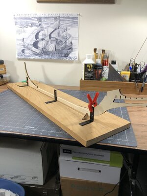
Thanks.
Interesting way - and very interesting to follow your work and the construction method 
Very nice work indeed Maarten 
Should your keel support blocks not be surrounded by Mud to be a true recreation?

 Only kidding but there's a thought for a diorama
Kind Regards
Nigel
Should your keel support blocks not be surrounded by Mud to be a true recreation?


 Only kidding but there's a thought for a diorama
Kind Regards
Nigel


