• Ships of Scale has incorportated an extra level of security when you log In. Please follow on-screen prompts to acknowledge that you are not a robot via a "Check Box" or a "Pictorial Check Box Puzzle". This is needed due to higher level of AI Activity Security.
  • SUBSCRIBE TO SHIPS IN SCALE TODAY!

    The beloved Ships in Scale Magazine is back and charting a new course for 2026!
    Discover new skills, new techniques, and new inspirations in every issue.

    NOTE THAT OUR NEXT ISSUE WILL BE July/August 2026
  • Win a Free Custom Engraved Brass Coin!!!
    As a way to introduce our brass coins to the community, we will raffle off a free coin during the month of August. Follow link ABOVE for instructions for entering.

A Katwijk Bomschuit

Update 15
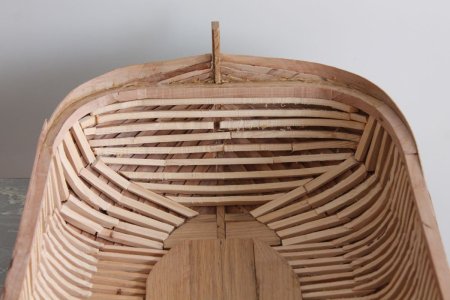
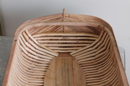
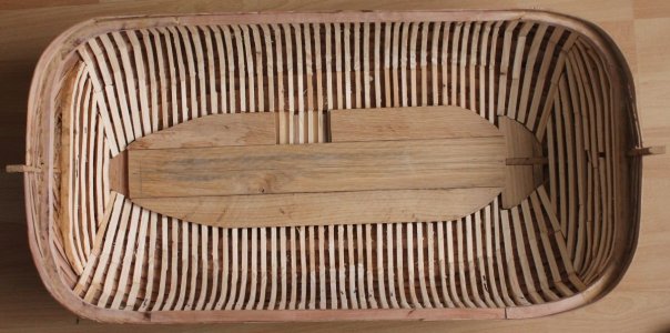
Almost all of the internal frames and strakes have been installed.
Here’s a look at the bow:
15-1-Boeg.jpg
An inner stem will be added in the middle to seal the gap in the third strake.
And the stern:
15-2-Achter.jpg

Two more strakes need to be added here.

And an overview:
15-3-totaal.jpg


Next up is a lot of sanding, then attaching all the nails on the outside, and finally covering the inside.
To be continued.
 
Update 16
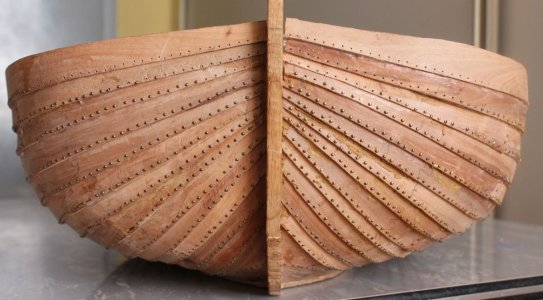
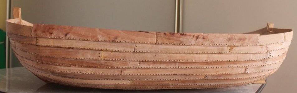
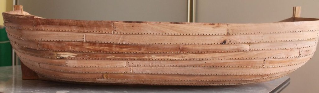
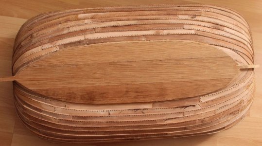
Lately, I’ve been doing nothing but carpentry. All the planks of a bomschuit are nailed together at the overlapping sections. A gangway is 85 cm on average, and I have 12 and a half of them on both sides. In reality, the nails are spaced 10 cm apart, so on the model they’re 5 mm apart. That comes to a total of 2 × 12.5 × 85 × 2 = 4,250 nails. For a standard bomschuit, it was stated that 3,500 rivet nails were needed. So that’s roughly correct.

The riveting was done as follows:
16-1-klinken.jpg

A rivet had a square cross-section with sides measuring 1 cm (3/8 “) and was galvanized at the shipyard. They were driven in from the outside toward the center. (1) Next, a “rose” was placed over the tip (a small square plate with a hole in the center). A hammer with a hole was placed over the nail tip and struck firmly with another hammer so that the two planks were sealed watertight against each other (2). Then, using the hammer with the hole, the tip was bent over and snapped off (3). Next, the broken-off tip was flattened (riveted) using two hammers alternately, while a third hammer held it in place from the outside (5).

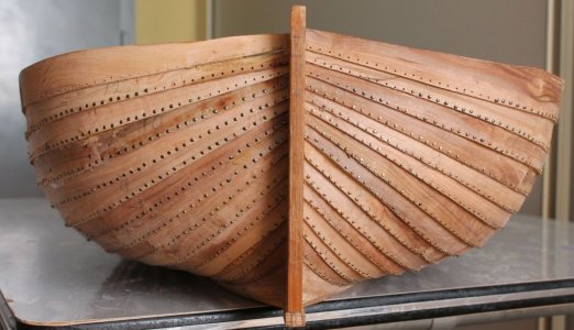
On my model, I simply hammered in two small round nails with rounded heads per centimeter, after pre-drilling the holes. This produces the following result:

The stern:
16-2-Achter.jpg

The bow:
16-3-Voor.jpg


Port side:
16-4-Bakboord.jpg

Starboard side:
16-5-Stuurboord.jpg

Bottom:
16-6-Onderkant.jpg

Inside:
16-7-Binnenkant.jpg


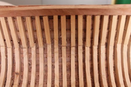
Here you can see why I attached the wooden strips first and then the nails.
If I hadn’t done that, I would have had to hammer all the nails flat first before I could install the wooden strips. That would have been much more difficult. Now you can see some of the nails sticking out of the wall, while others are nailed into the wooden strips.
The interior paneling simply goes over this. Except for a small section, which is left open to show a bit of the structure.

To be continued
 
Update 16
Lately, I’ve been doing nothing but carpentry. All the planks of a bomschuit are nailed together at the overlapping sections. A gangway is 85 cm on average, and I have 12 and a half of them on both sides. In reality, the nails are spaced 10 cm apart, so on the model they’re 5 mm apart. That comes to a total of 2 × 12.5 × 85 × 2 = 4,250 nails. For a standard bomschuit, it was stated that 3,500 rivet nails were needed. So that’s roughly correct.

The riveting was done as follows:
View attachment 620359

A rivet had a square cross-section with sides measuring 1 cm (3/8 “) and was galvanized at the shipyard. They were driven in from the outside toward the center. (1) Next, a “rose” was placed over the tip (a small square plate with a hole in the center). A hammer with a hole was placed over the nail tip and struck firmly with another hammer so that the two planks were sealed watertight against each other (2). Then, using the hammer with the hole, the tip was bent over and snapped off (3). Next, the broken-off tip was flattened (riveted) using two hammers alternately, while a third hammer held it in place from the outside (5).

On my model, I simply hammered in two small round nails with rounded heads per centimeter, after pre-drilling the holes. This produces the following result:

The stern:
View attachment 620360

The bow:
View attachment 620361


Port side:
View attachment 620362

Starboard side:
View attachment 620363

Bottom:
View attachment 620364

Inside:
View attachment 620365


Here you can see why I attached the wooden strips first and then the nails.
If I hadn’t done that, I would have had to hammer all the nails flat first before I could install the wooden strips. That would have been much more difficult. Now you can see some of the nails sticking out of the wall, while others are nailed into the wooden strips.
The interior paneling simply goes over this. Except for a small section, which is left open to show a bit of the structure.

To be continued
A lot of labour works, but the result is impressive, Jan. A few to go and then another chapter is done.
Regards, Peter
 
Update 17.
It’s been quite a while since the last update. Well, there were a few things that came up in the meantime, like an exhibition at the Maritime Museum. But we’re moving forward in good spirits.

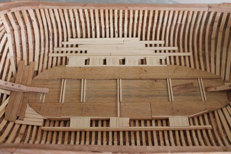
All the frames and timbers are in place, and the next step is the ceiling planking, also known as the “wegering.” Right next to the keelson, a section of the ceiling plaking can be removed.
I suspect this is so you can access the bottom to clean and dry it. The pump will be installed here in the stern later on.
17-1-BodemWegering.jpg

The instructions call for loose planks, but I decided to make them glued against each other. The cross slats on the keelson mark the spots where the transverse bulkheads will later be installed to divide the hold into compartments. On the top half of the picture mouonting the ceiling planking has started.

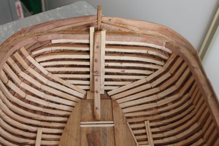
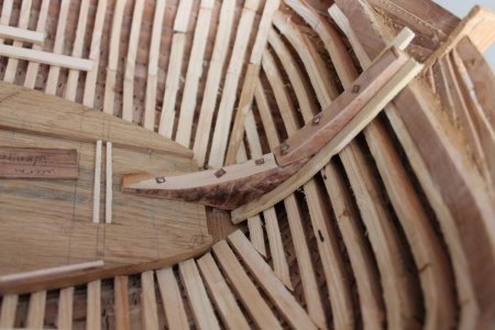
17-2-AchterBinnensteven.jpg
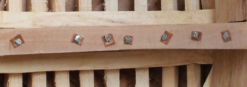
The inside of the stern is fitted with the inner stem. In the real boat, this is secured from the outside in with long bolts passing through the entire stem and fastened from the inside with nuts.

Here, I filed the head of a small nail into a square shape and tapped it through a small copper plate into a pre-drilled hole.
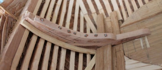
17-3-Closeup.jpg
A strip with bolt heads will also be attached to the outside of the stems.

From the side, it looks like this:
17-4-Achter-opzij.jpg

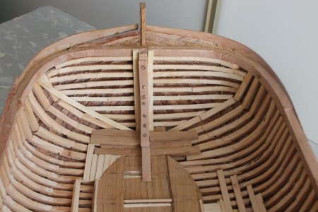
The fore stem is similarly fitted with an inner stem secured by bolts.
17-5-voor-opzij.jpg

On the inside of the bow, you can see how I'm going to attach the ceiling planking there.
17-6-wegeringvoor.jpg
Right next to the inner stem, a batten from the ceiling runs vertically. Next to it are a series of vertical battens, running perpendicular to the frames. These extend to the batten positioned at the junction of the horizontal and vertical frames. The battens of the side ceiling run horizontally against it there.

This pattern seems most logical to me, though it cannot be deduced from the construction drawings.
To make part of this structure visible later on, I’m leaving a small section next to the stem untouched. Later, the crew’s bunks will abut this area.

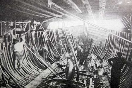
This photo provides a nice illustration of how this was done in the past.
17-7-Vroegerbs6.jpg

To be continued.
 
Back
Top