
I like your nice ,clean and sharp work.Good job!!

-

SUBSCRIBE TO SHIPS IN SCALE TODAY!
The beloved Ships in Scale Magazine is back and charting a new course for 2026!
Discover new skills, new techniques, and new inspirations in every issue.
NOTE THAT OUR NEXT ISSUE WILL BE July/August 2026 -

Win a Free Custom Engraved Brass Coin!!!
As a way to introduce our brass coins to the community, we will raffle off a free coin during the month of August. Follow link ABOVE for instructions for entering.
You are using an out of date browser. It may not display this or other websites correctly.
You should upgrade or use an alternative browser.
You should upgrade or use an alternative browser.
Armed Pinnace 1800 - Panart 1:16
- Thread starter Graham
- Start date
- Watchers 25
-
- Tags
- armed pinnace panart

Thanks very much, Zoltan.
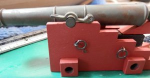
Finishing off the cannon carriage. The brass lock plate did not fit very well around the cannon trunnion -
- so I got to work with a rat-tail file -
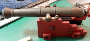
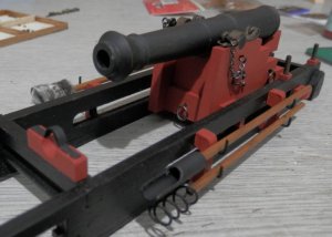
Carriage finished. In the end I painted the barrel matt black and then gently went over it with some fine wire
wool -
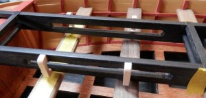
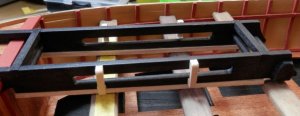
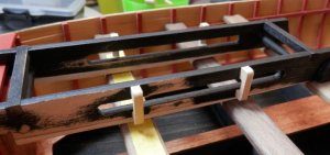
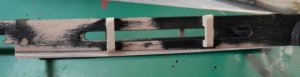
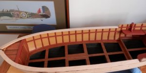
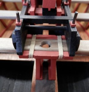
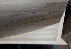
Back to the slide. It rests on the first three bench seats and, as you can see, there is an increasing gap running towards the bow -
I don't know why this is because everything measures up exactly. Whatever, I didn't like the look of this, so I glued on a strip and then chamfered it down -
It now sits down well and looks OK when painted. I don't think anyone will notice and you are the only guys who know, so don't tell anybody.
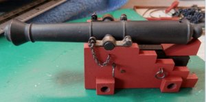
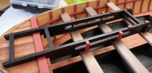
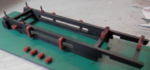
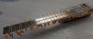
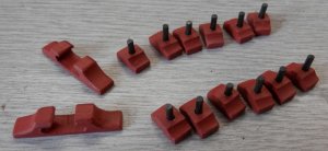
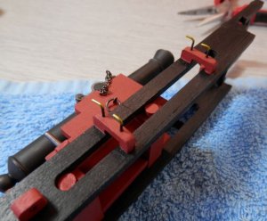
Various other bits glued on and the slide is now finished. The four red bits of dowel are the trunnions and note the two brackets towards the front on which a bowsprit could be mounted; the bowsprits (2 off) are yet made and will be strapped to the side of the ship later in the build.
Time to put the two assemblies together -
As I was building the benches and main cannon it set me thinking about the manning on this ship and I came up with:-
12 sailors to row
4 sailors to steer/handle the sails
4 sailors to man the main gun
4 sailors to man the two carronades
24 marines
That's 48 people at least; what's your view? Whatever the actual numbers were the boat would have been packed and one thing I do know for certain is that when they fired that big gun I would be the one standing as far away as possible thinking 'I hope that bloody thing is well bolted down!'
Finishing off the cannon carriage. The brass lock plate did not fit very well around the cannon trunnion -
- so I got to work with a rat-tail file -
Carriage finished. In the end I painted the barrel matt black and then gently went over it with some fine wire
wool -
Back to the slide. It rests on the first three bench seats and, as you can see, there is an increasing gap running towards the bow -
I don't know why this is because everything measures up exactly. Whatever, I didn't like the look of this, so I glued on a strip and then chamfered it down -
It now sits down well and looks OK when painted. I don't think anyone will notice and you are the only guys who know, so don't tell anybody.
Various other bits glued on and the slide is now finished. The four red bits of dowel are the trunnions and note the two brackets towards the front on which a bowsprit could be mounted; the bowsprits (2 off) are yet made and will be strapped to the side of the ship later in the build.
Time to put the two assemblies together -
As I was building the benches and main cannon it set me thinking about the manning on this ship and I came up with:-
12 sailors to row
4 sailors to steer/handle the sails
4 sailors to man the main gun
4 sailors to man the two carronades
24 marines
That's 48 people at least; what's your view? Whatever the actual numbers were the boat would have been packed and one thing I do know for certain is that when they fired that big gun I would be the one standing as far away as possible thinking 'I hope that bloody thing is well bolted down!'
Attachments
-
 P8230158.JPG54.1 KB · Views: 310
 -
 P8230159.JPG63.1 KB · Views: 311
 -
 P8240163.JPG70.9 KB · Views: 316
 -
 P8220154.JPG79.7 KB · Views: 313
 -
 P8220155.JPG64.4 KB · Views: 307
 -
 P8220156.JPG76 KB · Views: 308
 -
 P8220157.JPG45.8 KB · Views: 315
 -
 P8230162.JPG78.6 KB · Views: 313
 -
 P8240167.JPG66.8 KB · Views: 311
Ok, I have thought about it. No, my planking is not going to look this good. you got me beat !!! 
Thanks Donnie, but I think you do yourself a dis-service!
This week has been a lot of bitty but time consuming elements, so here's what has been going on.
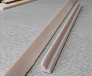
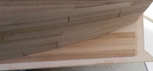
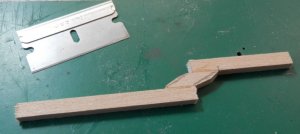
There are 6 bench seats and 4 end brackets on each. I wanted to cut them from a length of pre-shaped wood section but the choice was very limited at the DIY shop this time around. So, I got a length of triangular balsa (left) and got to work with some sandpaper to get the profile I wanted (right) -
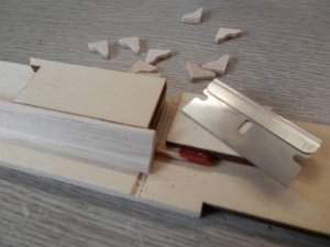
Then I made a jig to cut them to size -
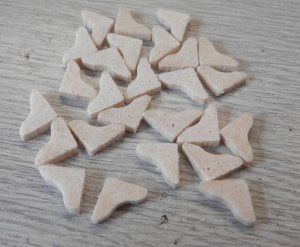
... and this is the result -
They painted up OK, but being balsa they really soak up the paint so several coats were required -
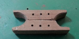
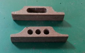
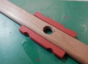
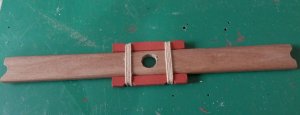
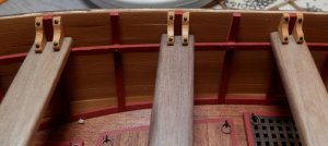
On to the parts which fix on the handrail - the fwd rope guide and the oar mounts. These are made by clamping two sections of wood together, drilling through and then quite a bit of work sanding and filing. I seemed to have been fiddling with these for ages -
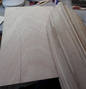
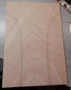
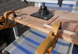
Now the handrail. In the instructions it is made up of seven different pieces. That just sounds like a headache waiting to happen so I got some thin ply and marked the rails out -
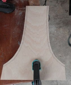
I left it clamped to the bench to sort out the inner profiles with the sander as it's easier to handle -
Trial fit -
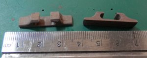
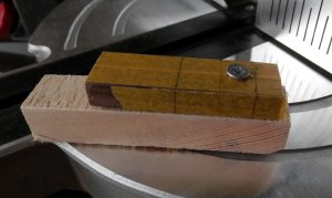
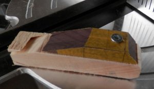
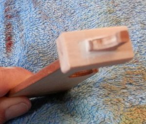
Mast mounting. The mast passes through a hole in the third bench and locates in a shoe which attaches to the deck. I shaped the shoe on the chop saw - it is screwed to a piece of sacrificial wood in order to save my fingers -
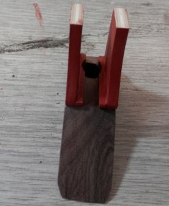
... and now the bench -
... and this is how it comes together -
This week has been a lot of bitty but time consuming elements, so here's what has been going on.
There are 6 bench seats and 4 end brackets on each. I wanted to cut them from a length of pre-shaped wood section but the choice was very limited at the DIY shop this time around. So, I got a length of triangular balsa (left) and got to work with some sandpaper to get the profile I wanted (right) -
Then I made a jig to cut them to size -
... and this is the result -
They painted up OK, but being balsa they really soak up the paint so several coats were required -
On to the parts which fix on the handrail - the fwd rope guide and the oar mounts. These are made by clamping two sections of wood together, drilling through and then quite a bit of work sanding and filing. I seemed to have been fiddling with these for ages -
Now the handrail. In the instructions it is made up of seven different pieces. That just sounds like a headache waiting to happen so I got some thin ply and marked the rails out -
I left it clamped to the bench to sort out the inner profiles with the sander as it's easier to handle -
Trial fit -
Mast mounting. The mast passes through a hole in the third bench and locates in a shoe which attaches to the deck. I shaped the shoe on the chop saw - it is screwed to a piece of sacrificial wood in order to save my fingers -
... and now the bench -
... and this is how it comes together -
Attachments
-
 a.JPG55.1 KB · Views: 462
 -
 b.JPG62.5 KB · Views: 462
 -
 c.JPG72.2 KB · Views: 456
 -
 d.JPG87.1 KB · Views: 454
 -
 e.JPG53 KB · Views: 449
 -
 f.JPG49.6 KB · Views: 442
 -
 g.JPG73.1 KB · Views: 446
 -
 h.JPG86.3 KB · Views: 453
 -
 i.JPG49.9 KB · Views: 453
 -
 j.JPG40.8 KB · Views: 450
 -
 k.JPG48.5 KB · Views: 470
 -
 l.JPG70.9 KB · Views: 474
 -
 m.JPG75.2 KB · Views: 471
 -
 n.JPG59.7 KB · Views: 464
 -
 o.JPG50.8 KB · Views: 458
 -
 p.JPG71.7 KB · Views: 459
 -
 q.JPG60.3 KB · Views: 469
 -
 r.JPG49.3 KB · Views: 474

That is a lot of work for a small vessel. Great job. You are approaching it as if it was a scratch build.
Second post of the day; I must have maxed the last one out with too many photos.
I got to thinking yesterday that I had not yet seen the cannon balls for the two types of cannon. I had a good look around and even went through the waste bin - I have always started a model with an empty bin and never empty it until a build is finished, just in case anything gets thrown away in error. No joy there, either. In the end I called Cornwall Model Boats where I got the kit from and explained the situation. They rang me back an hour later to say that they have checked and Mantua no longer put the cannonballs in the kit as a cost-cutting measure. Can you believe that?!
Oh well, guess I'll mic up the barrels and get some on order but I'll wait a while until near the end of the build as I wonder what else is missing? On with the build and time to finish off the exterior of the hull so that I can stain it; a couple of jobs left to do.
Firstly planking the remaining dead keel area -
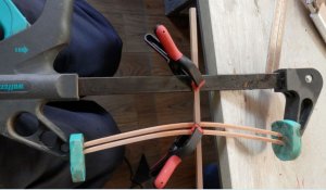
There is a rubbing strake on the lower side of the hull (port & stbd). This is made from 3mm x 5mm strip and needs to conform to the curvature of the hull. I soaked the strip in hot water for an hour and then went at it with the heated iron. I achieved some curvature, but not enough, because I'm trying to bend 5mm. After some thought I put the strips in one of my large woodworking clamps and ran it under hot water whilst tightening it slowly - somewhat nerve-wracking! It is also braced across to stop the strips skewing -
It was a bit of a guesstimate on the curvature needed, but when I got what I thought was the correct bend I left it for an hour then went over it with a hairdryer to set the wood. The above photo looks like quite a contraption, but I think we got away with it -
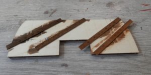
Time to think about stain colour. After several mixes (I prefer oil-based stain) I will go with the shade on the right -
I got to thinking yesterday that I had not yet seen the cannon balls for the two types of cannon. I had a good look around and even went through the waste bin - I have always started a model with an empty bin and never empty it until a build is finished, just in case anything gets thrown away in error. No joy there, either. In the end I called Cornwall Model Boats where I got the kit from and explained the situation. They rang me back an hour later to say that they have checked and Mantua no longer put the cannonballs in the kit as a cost-cutting measure. Can you believe that?!
Oh well, guess I'll mic up the barrels and get some on order but I'll wait a while until near the end of the build as I wonder what else is missing? On with the build and time to finish off the exterior of the hull so that I can stain it; a couple of jobs left to do.
Firstly planking the remaining dead keel area -
There is a rubbing strake on the lower side of the hull (port & stbd). This is made from 3mm x 5mm strip and needs to conform to the curvature of the hull. I soaked the strip in hot water for an hour and then went at it with the heated iron. I achieved some curvature, but not enough, because I'm trying to bend 5mm. After some thought I put the strips in one of my large woodworking clamps and ran it under hot water whilst tightening it slowly - somewhat nerve-wracking! It is also braced across to stop the strips skewing -
It was a bit of a guesstimate on the curvature needed, but when I got what I thought was the correct bend I left it for an hour then went over it with a hairdryer to set the wood. The above photo looks like quite a contraption, but I think we got away with it -
Time to think about stain colour. After several mixes (I prefer oil-based stain) I will go with the shade on the right -
Attachments
Thanks Gary. I hadn't thought of it like that and, yes, there are quite a few parts which you could reasonably expect to be laser cut from teak but have to be made from scratch.
However, I fear that progress on the build will slow down for a while due to our new arrival. Everyone please say hello to Evie -
However, I fear that progress on the build will slow down for a while due to our new arrival. Everyone please say hello to Evie -
Attachments
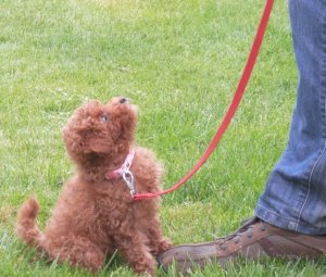
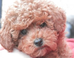

Beautiful work Graham and a beautiful little dog as well, enjoy,
best regards John.
best regards John.
Thanks John - on both counts!
Evie has settled in really well, so I have managed to get some ship work done.
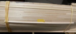
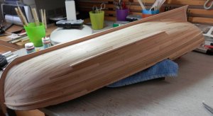
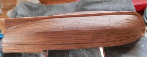
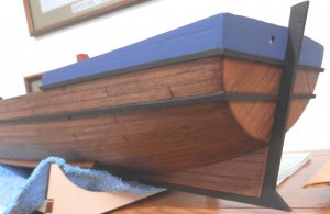
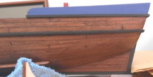
This is the external hull now finished, all necessary bits stuck on and ready for staining -
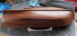
Stained -
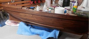
After three coats of acrylic lacquer (that will be enough) -
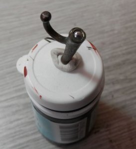
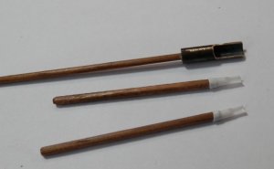
While the lacquer is hardening off I'll make the cannon loading equipment and boat hook. First problem is that the boathook end has a ball bearing jammed in it! -
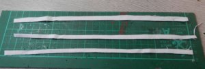
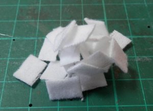
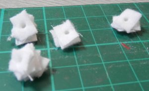
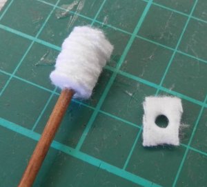
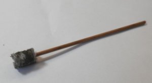
Strange, and it won't come out, so I guess I'll just put a recess in the shaft and hope the CA holds. First the barrel swab. I used some felt-like material stolen from the sewing room. The following photos tell the sequence -
Put a dab of CA on the shaft as you slide up each square; roughly trim to shape with sharp scissors, then rub on sandpaper to fluff up, then a bit of weathering powder.
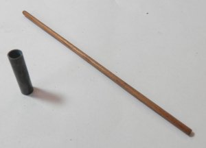
Powder scoop next. I decided to make sets for the two swivel guns as well, but there is no brass tube for these so I used plastic tube -
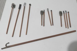
Worm screws are made from brass wire wound around a drill bit appropriate to the size of the cannon bore. Here's the finish, all three sets painted up -
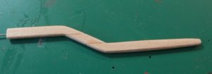
On to the rudder. The tiller arm is supposed to be bent from one piece of wood, but from my recent experience with the rubbing strakes there is no way to get those severe bends into that size wood. So, since it is to be painted anyway I decided to laminate it -
I think that turned out OK. The tiller arm attaches to a block which sits over the rudder at an angle, so in order for this block to slide on the rudder you have to cut a square hole on an angle. This did not go too well, but since it is to be painted I got away with using filler. Quite a bit of filler.
I did not take a picture before I used the filler because you will talk about me.
Evie has settled in really well, so I have managed to get some ship work done.
This is the external hull now finished, all necessary bits stuck on and ready for staining -
Stained -
After three coats of acrylic lacquer (that will be enough) -
While the lacquer is hardening off I'll make the cannon loading equipment and boat hook. First problem is that the boathook end has a ball bearing jammed in it! -
Strange, and it won't come out, so I guess I'll just put a recess in the shaft and hope the CA holds. First the barrel swab. I used some felt-like material stolen from the sewing room. The following photos tell the sequence -
Put a dab of CA on the shaft as you slide up each square; roughly trim to shape with sharp scissors, then rub on sandpaper to fluff up, then a bit of weathering powder.
Powder scoop next. I decided to make sets for the two swivel guns as well, but there is no brass tube for these so I used plastic tube -
Worm screws are made from brass wire wound around a drill bit appropriate to the size of the cannon bore. Here's the finish, all three sets painted up -
On to the rudder. The tiller arm is supposed to be bent from one piece of wood, but from my recent experience with the rubbing strakes there is no way to get those severe bends into that size wood. So, since it is to be painted anyway I decided to laminate it -
I think that turned out OK. The tiller arm attaches to a block which sits over the rudder at an angle, so in order for this block to slide on the rudder you have to cut a square hole on an angle. This did not go too well, but since it is to be painted I got away with using filler. Quite a bit of filler.
I did not take a picture before I used the filler because you will talk about me.
Attachments
-
 a.JPG67.4 KB · Views: 427
 -
 b.JPG69.3 KB · Views: 428
 -
 c.JPG49.9 KB · Views: 429
 -
 d.JPG57.5 KB · Views: 420
 -
 f.JPG60.4 KB · Views: 416
 -
 aa.JPG33.1 KB · Views: 413
 -
 bb.JPG58.6 KB · Views: 402
 -
 cc.JPG47.2 KB · Views: 397
 -
 dd.JPG53.2 KB · Views: 391
 -
 ee.JPG49.8 KB · Views: 385
 -
 ff.JPG35.8 KB · Views: 380
 -
 gg.JPG31.9 KB · Views: 375
 -
 hh.JPG38.4 KB · Views: 378
 -
 ii.JPG46 KB · Views: 379
 -
 jj.JPG67.1 KB · Views: 380
 -
 kk.JPG38.8 KB · Views: 371
 -
 ll.JPG56.6 KB · Views: 381

Very nice job Graham. This is the first time I've seen your build log but I'll be following it to the end now. I especially like the way you handled the making of the cannon tools. Very innovative.
Take care,
Bob
Take care,
Bob
Thanks Bob, much appreciated.
The drawings show the cannon equipment laying around in the boat, but I don't think that is the way any navy works so I made some hooks and hung it on the side of the carriage - all 'Ship-shape' as the saying goes.
The exterior of the hull is now finished; I will not be painting the lower part from the waterline down on this model. Some decoration is placed on the stern in the blue area (it is a lasercut pattern) but nothing is provided for the side areas. I am thinking on it, not sure yet and it can be done later when I figure it out.
Attachments
Hello Graham,everything just looks fabulous ,I checked out that german scale model flag website on a german forum and by the comments seems like a good quality supplier.
http://www.schiffsmodellflaggen.de/deutsch/Katalog/katalog.html
http://www.modelships.de/Flaggen-Beispiele.htm
http://www.schiffsmodellflaggen.de/deutsch/Katalog/katalog.html
http://www.modelships.de/Flaggen-Beispiele.htm
I have just enjoyed reading through your build log Graham, and I've picked up some great tips on boat building. I agree with you I certainly would not want to be on that boat when that gun was being fired,
Cheers Andy
Cheers Andy
Zoltan - thank you for the follow-up, very much appreciated.
Andy - thanks, I think it's important to share tips and techniques; not only what goes well but also what doesn't and how I fixed it - and there have been a few of those instances, believe me!
Andy - thanks, I think it's important to share tips and techniques; not only what goes well but also what doesn't and how I fixed it - and there have been a few of those instances, believe me!
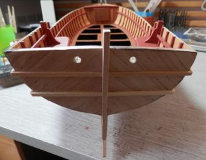
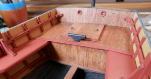
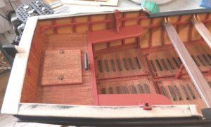
I was going to put the handrail on next, but it will not be possible to get the bench seats in as they won't angle in with the handrail in place. So, I'd better put the interior bits in; I was hoping to do this a bit later in order to save on getting them dusty, but never mind.
At the stern first. Extra nails fitted where necessary and the hawser holes are made from a couple of brass rivets painted up -
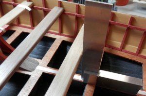
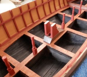
Next the bench supports and mast base. Measuring up -
... and fitted -
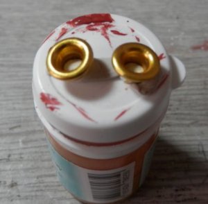
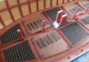
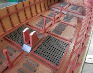
Now on to the gratings and hatches. I figure they'd need to lift them up somehow, so I made up some ring pulls (eyelet and brass ring) and put one on each corner -
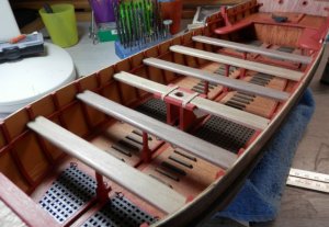
Bench seats in place -
... and brackets on the end -
Now I can get on with those handrails.
At the stern first. Extra nails fitted where necessary and the hawser holes are made from a couple of brass rivets painted up -
Next the bench supports and mast base. Measuring up -
... and fitted -
Now on to the gratings and hatches. I figure they'd need to lift them up somehow, so I made up some ring pulls (eyelet and brass ring) and put one on each corner -
Bench seats in place -
... and brackets on the end -
Now I can get on with those handrails.
Attachments
The front handrails went on easily and as I had used the hull for the two profiles it was straightforward. The rear side-rails needed bending, as did the piece on the transom. After a hot water soak some brute force was applied -
Then fitted -
.... and painted -
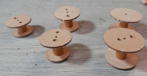
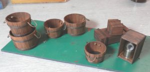
On to making some buckets. The circular profiles are laser cut and I used a length of dowel to space them -
Each stave had to be shaped separately so it was a bit time consuming. I have also made some boxes for the hell of it. Here they are in the rough -
Then fitted -
.... and painted -
On to making some buckets. The circular profiles are laser cut and I used a length of dowel to space them -
Each stave had to be shaped separately so it was a bit time consuming. I have also made some boxes for the hell of it. Here they are in the rough -
Attachments

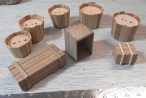
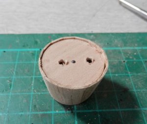
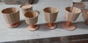
One of the barrels after a gentle going over with the palm sander. The top inner disc is now to be removed and before I put them together I drilled a couple of holes so I could get a dental pick in to hook it out. I also pinned them top and bottom to make them solid and that worked well considering the staves are only glued at the base and edges - no staves split during sanding. However, the pin stops the disc being removed, so I ground the top off and is came out easily.
Now what is removed can be stuck on the bottom as an aid to hold them when staining. Look like little wooden wine glasses!
All finished. I made a box for the compass and a couple of others as I have in mind a diorama, but that's just a rough idea at the moment.
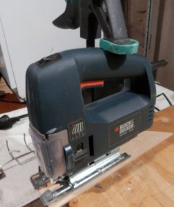
On to the oars. The shaft has a slot in it to take the oar blade. Previous experience on making a slot by drilling a line of holes and then using a knife and file has not been good. I do not have a bandsaw so what I did was make a baseplate and then clamp the jigsaw to the bench.
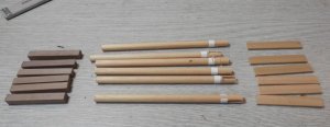
I used a fine toothed blade and then pushed the dowel towards it. There was some chatter of the workpiece because I'm not really using the jigsaw as is intended, but if you take it slowly is works fine and the end result is quite acceptable. Here are the pieces in the rough -
Now what is removed can be stuck on the bottom as an aid to hold them when staining. Look like little wooden wine glasses!
All finished. I made a box for the compass and a couple of others as I have in mind a diorama, but that's just a rough idea at the moment.
On to the oars. The shaft has a slot in it to take the oar blade. Previous experience on making a slot by drilling a line of holes and then using a knife and file has not been good. I do not have a bandsaw so what I did was make a baseplate and then clamp the jigsaw to the bench.
I used a fine toothed blade and then pushed the dowel towards it. There was some chatter of the workpiece because I'm not really using the jigsaw as is intended, but if you take it slowly is works fine and the end result is quite acceptable. Here are the pieces in the rough -
Attachments
Great build so far, from what I can see(most of your pictures were lost in the crash). I love those buckets and boxes, how many staves did you use in the buckets? This model is a good size for detailing and you are doing a fine job.
Thanks for your kind words, Don. Regarding your question, there are 19 staves in the larger bucket, 16 in the smaller.
Following your comment I checked all my posts/logs and all photos have gone. One day we will laugh about it, but not today.
Following your comment I checked all my posts/logs and all photos have gone. One day we will laugh about it, but not today.
Graham ,see my Pm please,thanks.