Armed Virginia Sloop - Lauck Street Shipyards, POF 1:32 Scale, Admiralty Style by DocBlake [COMPLETED BUILD]

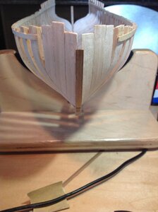
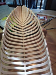
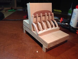
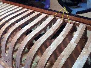
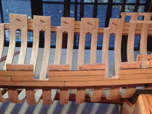
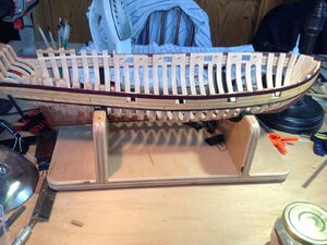
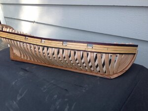
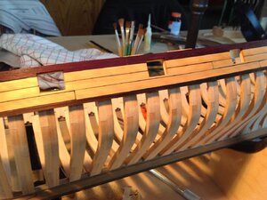
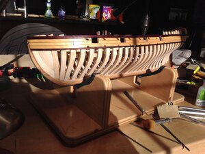
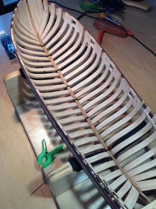
All of the frames are glued to the rising wood and the deadwood except the last two, P and Q. I had to remake the two pair of forward cant frames, because I didn't like the way they fit. They are much better now, and the fairing of the hull will be easier. I did rum into trouble with frame P, the next to the last one. Basically the kit pieces made for a set of frames that tended to "curl in" rather than line up with the upper futtocks of the frames that come before. The size of the finished frame doesn't leave enough excess wood to fair frame P into the same plane as the frames before. So I used the beveling template to make a new pair of frames, and beveled them to fit the hull curves at that station. Cutting out the futtocks and gluing them together is easy...fitting the frame in place without an accurate beveling template is hard. It took me a couple of hours to fit the new frames, but I like the end result.


The first photo shows the old frame P. It is the first one. Notice how the upper futtock is rotated inward. The second and third photos shows the new frame P before beveling. The forward edge of the frame is high compared to the frame in front, and the uppermost parts need to be shaped. The last three photos are of the final pair of frames P in position in the jig. The uppermost part flows more smoothly and the inside and outside surfaces are fair compared with the frame before. A great improvement. Once the poly is dry I'll glue this frame in place, fair the upper hull and install temporary ribbands to the frame tops. The model will be ready to come out of the jig.


View attachment 165173View attachment 165174View attachment 165175View attachment 165176View attachment 165177View attachment 165178
Love the colorful use of rubber bands to hold tension. Just what you had on hand, or did color make a difference?
 
Doc, Wow
amazing work, just a pleasure to see and read about your The construction methods and the impressive results.
I'm reading and browse through pictures and learn a lot from them Thumbs-UpFirst Place Metal
 
Thanks, guys! Admiralty rubber bands. I was sorry to have to cut them!

The hawse frames were completed and glued in place. Overall I'm happy with the fit. The first hawse frame is short, but that should be no problem because the kit was design with the hawse timbers and the first two cant frames long, so they can be custom cut for the model. Frame Q is also glued in place. That's where the wing transom sits. Next is fairing the hull.

38.jpg39.jpg
 
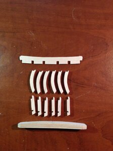
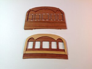
The transom framing and counter framing will be visible through the great cabin roof (poop deck) which will be partially planked. The kit provided the hull planking in hard maple, but counter and transom planking is in cherry. I just finished cutting out the components for this framing, including the wing transom, out of hard maple to match the general framing. To add some contrast, I redid the transom itself. The kit provides two pieces to form the transom. There is the transom proper (TR1) and an "overlay" trim piece (TR2). Both are made of cherry. I took the outline of the transom piece and traced it on some 1/64" plywood and planked both inside and out with swiss pear. I then remade the overlay piece out of boxwood to match the outer bulwark planking. Once the transom is fit in place, the bottom will be trimmed off and the overlay fitted with a plank as shown in the photo. The second transom in the photo is the two kit parts. I like the color contrast between the boxwood and swiss pear.


40.jpg41.jpg
 
I decided to build the stern assembly off the model as Mike S. did. This consists of the transom proper, the wing transom, the counter and transom framing and the transom beams. I built a jig to hold the parts securely while the glue dried. The jig is just scrap plywood joined at a 104 degree angle (14 degrees from the vertical). Fortunately I have a miter saw and it took just a few minutes to build. While the glue was drying, I started removing the tabs from the foot of each frame, so the frame flows smoothly into the rabbet along it's length. The hard maple is hard on blades too!. I'm about half done and I've gone through four X-Acto blades already. Once the tabs are removed and the hull gets it's final fairing, I'll glue the stern assembly in.

I then trimmed the little tabs that were used to stabilize the frames when they were glued to the rising wood and deadwood. There are three left to do! You can see from the photo how each frame flows smoothly into the rabbet. My next task is the final hull sanding and attaching the counter and transom.

42.jpg43.jpg
 
I added the black strake and three boxwood strakes above it. The practicum calls for adding a 4th strake and then framing in the gun ports. The ports are then opened up by drilling holes at the corners, and connecting the holes with an X-Acto knife. The better way is to cut the ports BEFORE adding the 4th strake! I used a razor saw and cut down using the hull frames as a guide. The bottom of the port is formed by using a #10 X-Acto to define the line and then sawing through the half frame that needs to be removed with a #13 blade. A file cleans up the edges. As you can see they are crisp and straight. Once the last strake is added to the top off the port, the top edge is defined again with an X-Acto. Please excuse the planking. It hasn't been sanded so the grit, glue stains and unevenness show up well. It WILL look better when done!


I then added the shear strake and completed framing the gun ports. After the glue is cured I will cut away the shear strake to the top of the port frame to define the upper edge of the gun port. On the old MS model of the Armed Virginia Sloop, many builders painted the shear strake to add a little decoration. I decided to make mine out of purpleheart and not paint it. (Photo


44.jpg45.jpg46.jpg47.jpg
 
Interesting kit. I have finished the framing section and starting the planking. I plan to plank the hull with cherry. That raised the problem of planking since the kit from LSS does not include the wood for this. I have four packets of 1/4" x 2 1/4" x 24" billets of Cherry that I purchased a number of years ago from Dave at The Lumberyard. 14 hours later. I now have: one-billet at 5/32" for the scupper strake. one-billet at 4/32" for the wale, seven - billets at 3/32" for the planks, and two billets at 2/32" for the decking. Next step is to make my tree nail stock. In this time of staying safe, one can get a lot done, if you want to.
 
Interesting kit. I have finished the framing section and starting the planking. I plan to plank the hull with cherry. That raised the problem of planking since the kit from LSS does not include the wood for this. I have four packets of 1/4" x 2 1/4" x 24" billets of Cherry that I purchased a number of years ago from Dave at The Lumberyard. 14 hours later. I now have: one-billet at 5/32" for the scupper strake. one-billet at 4/32" for the wale, seven - billets at 3/32" for the planks, and two billets at 2/32" for the decking. Next step is to make my tree nail stock. In this time of staying safe, one can get a lot done, if you want to.
@DocBlake Dave, sorry to highjacking your thread...

@Feathermerchant We (SOS members) would love to see your Armed Virginia Sloop model building progress. Is it possible for you to open your own building log? It is very easy and BTW, doesn't have to be from the beginning. If you have questions or help, you can ping me or staff on-line. Looking forward to your build log! :)

I'd love to see it, also! Besides Bob Hunt's prototype, Mike and mine are the only two of this model I've ever seen! Please post!
 
Scuppers and sweep ports cut into the port side. The scuppers are bigger than they should be because when drilling the pilot hole to cut out one of them, the drill came out too high on the plank above the black strake. All the scuppers had to be bigger to compensate. Still, I think it looks OK. It's just one of those things that the builder notices, but no one else usually does on the finished model.

48.jpg
 
Beautiful Doc. On retrospect, you could always go back and put small inserts into those scuppers to simulate the liners. I could be wrong but I believe those scuppers had some sort of lead or copper liner so that the drainage would not rot the wood.... ????? Then instead of saying that you made an error, you could just say it is "super detailed"... :cool:
 
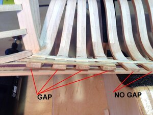
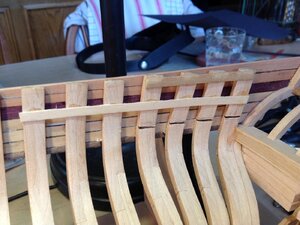
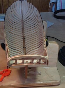
I tackled a problem with the transom today. Because of problems with the lofting of the after cant frames, the frames did not line up with the transom. The last 4 frames tended to curve inward, like the bow, rather than flow straight to the transom. The only solution was to cut each of the final frames and "bend" them outward to meet the planking which is already in place. The frames were then glued to the planking,and when the glue is completely dry, I'll fair the inside of the hull where the "surgery" took place prior to planking the inner bulwarks. It was REALLY difficult to chuck a cutoff wheel into my Dremel and cut the frames off after all the work that went into building them! Fortunately, I'm planking both sides of the model down to the wales, inboard and outboard, so the "fix" will not show.

The first photo shows the problem, the second shows the cuts and the third shows the frames straightened out and glued to the planking.

Now on to the port side! 50.jpg51.jpg52.jpg
 
Back
Top