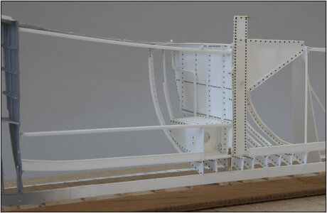
BALDER, Vlaardingen Herring Lugger from 1912, scratch build scale 1:50 Plate-On-Frame

Just stumbled across this build, I have been interested in building a confederate paddle steamers and was wondering how to build one and show at least the cargo hold and its construction. Using your method I could construct the entire model in this manner. Great start, I will be following for the entirety of your build and perhaps I will learn a new way to construct a model!
 
This is absolutely a very special build. I remember an over 2 meters long model in the Visserijmuseum in Maassluis, made by Jo Ploeg. It was entirely executed in brass and I hope it is still in the exhibition (I haven't been there for years). I very much like your approach and method, showing a ship under construction. As far as I am concerned every stage of this build could be the end stage.
Bravo!
 
Just stumbled across this build, I have been interested in building a confederate paddle steamers and was wondering how to build one and show at least the cargo hold and its construction. Using your method I could construct the entire model in this manner. Great start, I will be following for the entirety of your build and perhaps I will learn a new way to construct a model!
Hi, thanks for your reaction. As you can see in my signature, I have build the Robt. E. Lee with in the front the structure of beams and braces. But with the knowledge I now gain from this construction, I might have approached it differently. Those steamers have a combination of wood and cast iron. I made the model mostly out of wood and some walls of thick paper.
I'm very curious about your plans and which steamer you want to build.
Regards, Peter
 
This is absolutely a very special build. I remember an over 2 meters long model in the Visserijmuseum in Maassluis, made by Jo Ploeg. It was entirely executed in brass and I hope it is still in the exhibition (I haven't been there for years). I very much like your approach and method, showing a ship under construction. As far as I am concerned every stage of this build could be the end stage.
Bravo!
Thanks for your post and compliments, Ab. I will look for that model or information about it.
And about the building proces of progress, it's just like the old shipyard, every step during the construction process can stand still and has its own charm. I don't lack the will and energy, especially with the next steps ahead. Such as painting the front part later so that the now far too dominant-looking rivets regain their visual appeal.
Then I'll see if I can/should do something about the planking on the inside or a bit of plating on the outside.
Regards, Peter
 
This is certainly the most fascinating build I've followed. So outside my realm of experience. It's a revelation at every stage, and with each new entry.
 
This is certainly the most fascinating build I've followed. So outside my realm of experience. It's a revelation at every stage, and with each new entry.
Hi Peter, you also thanks for this nice words and compliments.
I hope to keep the upcoming posts interesting. For now it’s just adding frames and keeping everything aligned.
Regards, Peter
 
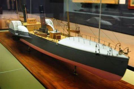
Hi Peter, thanks for response on your method of construction. Attached is the type paddle steamer that I was interested, I did quite a lot of research on them and have several sets of plans. Most of them except the earlier ships were built in GB so many plans are really available. The early ones were not purpose built and almost always wooden sailing ships . During the Civil War they went from wood to Iron to steel. The ones of Iron and steel would be constructed as your current model. PS HOPE is a popular ship to model as there are many models and good plans of her. I would like to construct something other than Hope but similar.

1709776802140.png
 
Hi Peter, thanks for response on your method of construction. Attached is the type paddle steamer that I was interested, I did quite a lot of research on them and have several sets of plans. Most of them except the earlier ships were built in GB so many plans are really available. The early ones were not purpose built and almost always wooden sailing ships . During the Civil War they went from wood to Iron to steel. The ones of Iron and steel would be constructed as your current model. PS HOPE is a popular ship to model as there are many models and good plans of her. I would like to construct something other than Hope but similar.

View attachment 433185
That’s a nice and interesting model. I hope you can/will start soon with a model like the HOPE. Looking forward to the build-log.
Regards, Peter
 
Hi Peter, thanks for response on your method of construction. Attached is the type paddle steamer that I was interested, I did quite a lot of research on them and have several sets of plans. Most of them except the earlier ships were built in GB so many plans are really available. The early ones were not purpose built and almost always wooden sailing ships . During the Civil War they went from wood to Iron to steel. The ones of Iron and steel would be constructed as your current model. PS HOPE is a popular ship to model as there are many models and good plans of her. I would like to construct something other than Hope but similar.

View attachment 433185
I see you have pictured the Purpose-Built Confederate Blockade Runner "Hope", 1864. There is the exhaustively researched Sea Watch book with text and plans by Vince McCullough and text and model by Gilbert (Gib) McArdle. A great collaboration by two fine master modelers. As always with Sea Watch books, worth the price of admission! Thumbs-Up
 
Yes that's the HOPE! The most modeled of the paddle steamers. Kind of like the Constitution or the Cutty Sark. You've peaked my interest again I'll have to dig out all of my material on them.
I'm partial to the CSS "Banshee". Those purpose-built blockade runners are like rail dragsters, real fast in a straight line. 0 maneuverability.
 
First of all, I would like to thank everyone for reading, following and/or liking my posts. It encourages me to go further.OkayThumbs-Up

That's why I also want to tell you what my considerations are now that I'm running into something again.
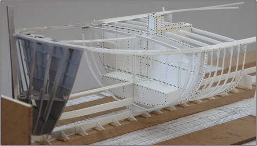
I am now working on the frames for the forecastle. And must take into account the profiles to support the floor.
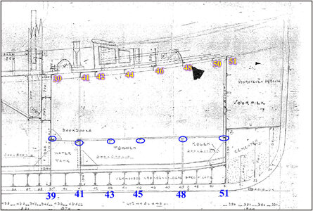
First this drawing from 1911:
0201 Vloer.jpg
I have circled the floor profiles with corresponding frame numbers. At the top of the numbered deck beams.

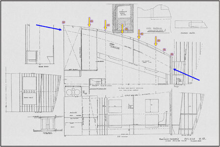
In the book of the 1st restoration in Amsterdam I came across this drawing by Syben de Jong:
0202 Vloer.jpg
(Source: Restoration book Scheepvaartmuseum, pag. 90: Drawing from S. de Jong)
It takes some puzzling because it is a combination of side, top and front views of the layout of the forecastle.
The deck beams are also drawn here with dotted lines, see the yellow arrows. On the side near the yellow arrows also the frames with numbers. The big difference here is that the front bulkhead is 52 and on the old drawing it is 51.
A significant difference between the Balder and the 1911 drawings: an extra frame, which affects the distances between the frames and the entire size of the forecastle.

I already found this out in the combination drawing of a previous post and scaled the layout of the forecastle in the 1911 drawing. Because I have to maintain that frame layout due to my design in Fusion.

With the 2 blue arrows I have indicated the line that indicates the side of the floor in the bilge. There will be a longitudinal profile to support the floor planks. This must be at the same height as the floor profiles.

The trade-off:
If I were to also make the floor profiles when making the frames, I would have to insert the longitudinal profile in parts in between. With the difficulty of turning it flowing lengthwise.
I have decided to apply the longitudinal profile first. As one whole piece, because then it helps to neatly align the frames in the bilge. And then adding the transverse floor profiles.

In the meantime I also built something.
The old construction specifications still says this about the water tank:
"For cleaning the tanks, a manhole of sufficient size is fitted on a forged ring and properly packaged.
To fill, a tube must be closed from the deck with a copper deck screw. The necessary air pipes are drained to the deck on the sides, ending under the railing with a folded end.
"
The air tubes installed from the sides of the tank to the stringers:
0203 Air.jpg
Frame 40 also installed and runs nicely around the ends of the watertank.
The filling tube will join the manhole later, when I am working on the design later. Have to check that on the Balder as well.
Then I can 'just' continue making the frames.
Regards, Peter
 
Last edited:
First of all, I would like to thank everyone for reading, following and/or liking my posts. It encourages me to go further.

That's why I also want to tell you what my considerations are now that I'm running into something again.
I am now working on the frames for the forecastle. And must take into account the profiles to support the floor.
First this drawing from 1911:
View attachment 433481
I have circled the floor profiles with corresponding frame numbers. At the top of the numbered deck beams.

In the book of the 1st restoration in Amsterdam I came across this drawing by Syben de Jong:
View attachment 433482
(Source: Restoration book Scheepvaartmuseum, pag. 90: Drawing from S. de Jong)
It takes some puzzling because it is a combination of side, top and front views of the layout of the forecastle.
The deck beams are also drawn here with dotted lines, see the yellow arrows. On the side near the yellow arrows also the frames with numbers. The big difference here is that the front bulkhead is 52 and on the old drawing it is 51.
A significant difference between the Balder and the 1911 drawings: an extra frame, which affects the distances between the frames and the entire size of the forecastle.

I already found this out in the combination drawing of a previous post and scaled the layout of the forecastle in the 1911 drawing. Because I have to maintain that frame layout due to my design in Fusion.

With the 2 blue arrows I have indicated the line that indicates the side of the floor in the bilge. There will be a longitudinal profile to support the floor planks. This must be at the same height as the floor profiles.

The trade-off:
If I were to also make the floor profiles when making the frames, I would have to insert the longitudinal profile in parts in between. With the difficulty of turning it flowing lengthwise.
I have decided to apply the longitudinal profile first. As one whole piece, because then it helps to neatly align the frames in the bilge. And then adding the transverse floor profiles.

In the meantime I also built something.
The old construction specifications still says this about the water tank:
"For cleaning the tanks, a manhole of sufficient size is fitted on a forged ring and properly packaged.
To fill, a tube must be closed from the deck with a copper deck screw. The necessary air pipes are drained to the deck on the sides, ending under the railing with a folded end.
"
The air tubes installed from the sides of the tank to the stringers:
View attachment 433483
Frame 40 also installed and runs nicely around the ends of the watertank.
The filling tube will join the manhole later, when I am working on the design later. Have to check that on the Balder as well.
Then I can 'just' continue making the frames.
Regards, Peter
Marvelous research and work Peter, I love the look of those pipes coming out of the tanks. Just curious, do you have to get in there and do some painting before you get too far along with the deck beams and side ribs?
 
Marvelous research and work Peter, I love the look of those pipes coming out of the tanks. Just curious, do you have to get in there and do some painting before you get too far along with the deck beams and side ribs?
Thanks, Daniel. For the paint job I can take both parts aside and have a good entrance to the inside:
0204 Open.jpg
If you mean 'inside the watertank(s)', I will only paint it to the sling shots. Behind the sling shot it will remains white, to maintain some contrast on the part behind it through the hole.
Regards, Peter
 
Back
Top