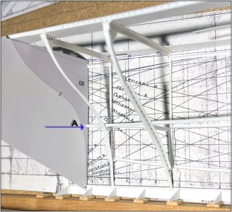
The construction of the starboard part is finished:

As I have already written, it was a good thing that I started at the front. With the experience gained, I could now complete the back. If I had started at that side with frame 0, I don't think I could show this acceptable result now.
The picture was taken from above with the building template tilted on the building floor.
On the freestanding building template:
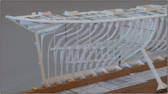
At first glance, the distance between the frames is not the same everywhere. That is correct. I will explain that later.
From a slightly lower position.

Also, some frames and retaining frames do not all point in the same direction.
Seen from this side, that is even more noticeable:

But here it is further reinforced by the strong double curvature of the frames. Which sometimes also gives a distorted image.
Some further explanation:

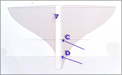
In the insert A (at the bottom of the photo) a part of the line plan that I used in Fushion to draw the frames. The distances between them differ. I have drawn the frames at the position of vertical lines. Actually, that is the position of the plate between the keel and the keelson.
And depending on how the deck profiles are placed, the frame and the reversing frame are placed on these plates.
I have shown that schematically in insert B. That corresponds to the construction method of frame 8.
In blue the L-shape deck profile where the flat top is facing left. The yellow shoulder corner plate is placed right against the standing side. And there again right of the red profile of the frame. See the small upper photo insert.
A little below that, the red reversing frame that is placed left against the frame starts and runs up to the cleat plate and bends horizontally over the top of that plate. See the small lower photo insert. That plate is again left of the frame and in line with the shoulder angle plate.
The black arrow points to the plate that is the basis of the placement.
I have numbered and framed frames 8 and 9. The horizontal top of the profiles point away from each other. The mizzen mast is secured between these profiles. So against the 2 flat sides of those profiles.
The frames point towards each other again. The retaining frames away from each other again.
In this way, the direction of the deck profiles, location and function are bound in several places in the hull. And determine the rest of the construction of the frames.
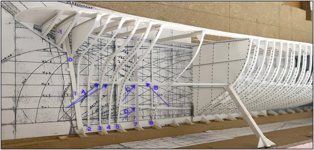
The rear was quite complex in terms of construction. The floor has the necessary horizontal profiles in which the floor beams will rest:

Between the deck and the floor 5 temporary uprights to keep the deck in position.
The floor is supported in the middle with 9 uprights. The Donkey steam boiler and the mizzen mast rest on that floor.
With an addition to the previous explanation:
The blue arrows point to the direction in which the flat top of the L-profiles of the deck beams point.
At frames 8 and 9 they point away from each other. The yellow arrows point to the retaining frames that also point away from each other. Because the frames it self ........
At the top the vertical lines that indicate the position of the shoulder angle plates. Their mutual distance based on the nearby placed frame of the line plan.
At the end a calm picture from a different angle:
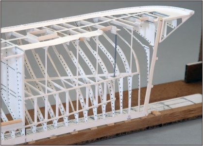
All curved profiles that from every angle again provide a (whether or not distorted) different image.
Now to work on placing a lot of rivets before this part can go to the paintshop.
Then there will be pictures of this whole starboard part.
Regards, Peter


