BN at the Mississippi River . . .

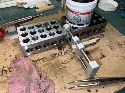
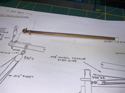
While continuing the daily frame building I took a couple days to work up the jumbo jib boom, replacing the one I charred while trying to solder a band. Using a drill bit held in a vise as the bending mandrel made much more sense than ruining the wood dowel like I did earlier. This aft end of the boom is now finished but the fwd end is still up in the engineering department. I do like my slightly-bored-to-fit styrene tube band but I just haven't yet figured out what to do about the traveler and horse. Decisions, decisions, decisions . . .
alf in Iowa
E9131611-FB49-4ADC-B5AA-156884B68BF2.jpeg3BD8E7B5-6301-4AE1-9ACF-3F511F96C4BB.jpeg
 
Oh my!, Foreboom dimensional issues.
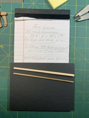
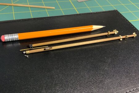
Continuing on with a frame or two a day and having set aside the Jumbo Jib Boom till the traveler horse gets designed, I took up the study of the Foreboom. Measurements being first and foremost I got out the caliper to see what YQ gave me, then checked to see what MS Lankford call for in their kit, and finally compared that stuff with whatever I might find in the BN2 Saga book.

As you can see there is a significant spar diameter difference between YQ and Lankford MS. In the pic the diameter disparity between the YQ kit stick (upper in the photo) and a 1/8" dowel (lower in the photo) is unmistakable. My gut sense is to go with the 6"-8"-6" (1/8" dowel) spar dimensions. Would any of you disagree with that? I'm open to being convinced otherwise:).
9AD7826D-B685-43DF-AE7B-FBAA55C04676.jpeg
 
Hi Alf. I suppose you will know: Keep in mind that the MS Lankford drawing are in scale 1:64. For the YQ scale of 1:72 you have to calculate it by 0.8889.
Jenson gives 6"-8"-6" and MS Lankford 3/32"-1/8"-3/32" in scale 1:64.
I am going to turn it off to those measurements in 1:72: 2.1mm-2.8mm-2.1mm = Jenson's ;). That's 5.3/64"-7/64"-5.3/64". And that's MS Lankford x 0.8889. :)
All those Imperials */8, */16", */32", */64" ........... Luckily I made myself a excel-file, so I can communicatie with you in "-talk. :)
Indeed: 138-5 is much to thick.
Regards, Peter
 
Last edited:
Hah, Peter. Yes about knowing the scale differences between the L/MS dwgs and YQ and very certainly nearly every page dwg in the Saga. What I do is work out each dwg dimensions from the dwg ratio to the equivalent full scale dimension _in both_ metric (2 decimal points) _and_ my native imperial system (three decimal points). That way I do all my actual thinking and planning in prototype full scale dimensions.

As an aside issue here, please tolerate a small rant from my perspective. I am very disappointed that Lankford/MS labeled the drawings in model dimensions rather that prototype dimensions. As a modeler who's been doing it for at least 70 years I "grew up" always thinking in terms of the prototype dimensions. In MODEL RAILROADER Magazine which I've been reading for 72 years, all their dwgs are labeled with prototype dimensions. If a box car truck (bogie) to Europeans) has a wheelbase of 5ft-6in that's how it's shown on the drawing. That covers every one of the myriad scales used in railroad modeling worldwide. A modeler in any scale can convert it to his own scale.

Lankford gives his foreboom three dimensions, 3/32"-1/8"-3/32; in his sheet scale of 3-1/16=1ft (1:64) those calculate to 6"-8"-6". I do agree that a 6-8-6 spar of 33 ft length does seem to be a tad light. But I really don't have any true life ship experience to guide me.

On the other hand, over 70 years I've learned that in modeling "finer or thinner" always looks to my eye better than does "heavier or thicker". If I have to round off a prototype dimension I always prefer to round down rather than up.

I like your response and if I have interpreted correctly, it seems you might agree that a 1/8" (3.175mm)dowel might be the most prototypical?
 
As an aside issue here, please tolerate a small rant from my perspective. I am very disappointed that Lankford/MS labeled the drawings in model dimensions rather that prototype dimensions. As a modeler who's been doing it for at least 70 years I "grew up" always thinking in terms of the prototype dimensions.
I wholeheartedly agree. Drawings in "model" dimensions is always reason for confusion and errors, the appropriate method is to use full scale (or 1:1) dimensions and identify the scale of the drawing in the title block. Fastest way to convert to any scale.
 
Hmm, it has occurred to me that in my quest for fidelity to prototype it may seem that I've been belittling the YQ kit. If so, I regret that.

Far from it, I am continually impressed that YQ produced such an elegant model kit for such a fair price. Accordingly I'll pay closer attention to how I describe my prototype research findings and my attempts at superdetailing.
alf in Iowa
 
Hi Alf. I suppose you will know: Keep in mind that the MS Lankford drawing are in scale 1:64. For the YQ scale of 1:72 you have to calculate it by 0.8889.
Jenson gives 6"-8"-6" and MS Lankford 3/32"-1/8"-3/32" in scale 1:64.
I am going to turn it off to those measurements in 1:72: 2.1mm-2.8mm-2.1mm = Jenson's ;). That's 5.3/64"-7/64"-5.3/64". And that's MS Lankford x 0.8889. :)
All those Imperials */8, */16", */32", */64" ........... Luckily I made myself a excel-file, so I can communicatie with you in "-talk. :)
Indeed: 138-5 is much to thick.
Regards, Peter
Would you share your excel file for other to use to make the change from imperial to metric.
 
Would you share your excel file for other to use to make the change from imperial to metric.
Hi Kurt. When it is pure for the calculation from Imperial to Metric, then I use this site with many kinds of calculation tables.
This one is very handsome:

Here I posted a short manual:

Regards, Peter
 
Hi Kurt. When it is pure for the calculation from Imperial to Metric, then I use this site with many kinds of calculation tables.
This one is very handsome:

Here I posted a short manual:

Regards, Peter
While I understand the desire or need to go to and fro other measurement systems, from personal experience, and no it ain't good, I'd like to recommend to use one measurement system and one system only. Murphy just loves confusion.
When we had to use imperial system, imposed upon us by our US customers, we were also forced by our manufacturing to use the metric units as well. I can tell you it created a lot of additional work ánd quite frequently epic misunderstandings.
You're right, Johan. My excuses for interrupting and I don't want to act as a moderator, but I don't think this is the discussion to have in Alf's build log. We just have to deal with it.
We're not going to solve that here either. We can try to make it easy for ourselves.
A sorry to Alf for this side-step ……. Sick
Regards, Peter
 
Last edited:
Hmm, it has occurred to me that in my quest for fidelity to prototype it may seem that I've been belittling the YQ kit. If so, I regret that.

Far from it, I am continually impressed that YQ produced such an elegant model kit for such a fair price. Accordingly I'll pay closer attention to how I describe my prototype research findings and my attempts at superdetailing.
alf in Iowa
Hi Alf. I can understand your point of view.
You only started showing the editing of some parts that will be discussed later according to the manual. And those that are ‘somewhat out of scale’.
With the keel and the frames you are largely involved in the construction of the hull that YQ has provided with beautiful pear wooden parts. Only posted the making of your keel and already making the frames.

You can also just build the structure like the kit it provides and a few of them have already been delivered.
But you can also be critical of certain parts. For some laborious ones, YQ has found a nice solution for this, such as the lettering on the stern and the ships wheel.
Other wooden parts can be adjusted to everyone's own insight.
You're not the first to comment. I think I've been a lot more critical and have done crazy things with the kit. But YQ has also responded appreciatively. They even showed it on a Chinese platform.
Regards, Peter
 
Last edited:
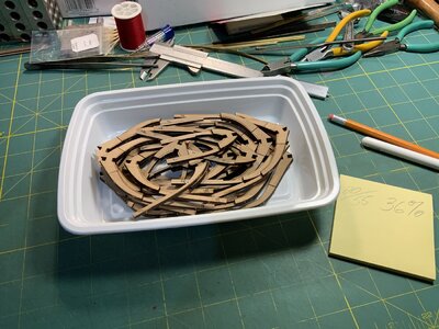
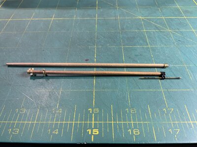
Today I reached a self-established marker of sorts; I finished gluing up the first factory stack of lasered frames, 20 frames. Let's see, . . . 20/55=36%. I won't convert that 36% from my American Imperial to Metric tho, I'll leave that for you guys around the rest of the world to do for yourselves.ROTF The base keel, well along, is hanging up on the wall on a picture hook safely tied up and out of the way. I finally got the traveler horse end engineered for the Jumbo Jib Boom so the boom is finished and set aside till needed. I've started making bands for the Foreboom and engineered the gooseneck parapharnalia using a 1:12 scale automotive banjo fitting I had on hand from an earlier Lotus 49 project. I think I deserve a couple ounces of a nice sweet Moscato.63110E6D-550A-4E79-B5D1-239CCED868EB.jpeg4CB71CDA-9C30-4438-AE7E-5A2CBF584027.jpeg
 
Last edited:
Hmm, it has occurred to me that in my quest for fidelity to prototype it may seem that I've been belittling the YQ kit. If so, I regret that.

Far from it, I am continually impressed that YQ produced such an elegant model kit for such a fair price. Accordingly I'll pay closer attention to how I describe my prototype research findings and my attempts at superdetailing.
alf in Iowa
Been there, seen that, done that, unfortunately.
At some point during my build I was very dissatisfied with how things went together and in the process blaming YQ. The deviations 's I had to deal with were of my own making, not something I could blame someone else for.
While one can't deny the YQ kit has various shortcomings, the overall quality and accuracy of the kit is great, plus it's a great kit to add one's own customizations.
 
So much for my spar-work break from gluing up frames: just now I finished up the Foreboom. Tomorrow I'll get back to the one or two frames a day construction and look for some other sub assembly kind of side project to break the repetition of the frame work.

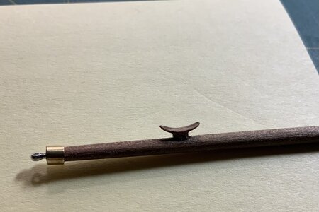
While fitting up the single boom tackle cleat this afternoon I pondered up a question. Would the prototype of that cleat have been made with a radiused bottom to fit the curve of the boom timber or might the boom have had a flat cheek adzed into its circumference? I did it the easy way and radiused the bottom of the cleat, but now I will spend some interesting hours poring over photos of sail booms. I did however drill both the boom and the cleat for an .019" wire pin to add a bit of strength in case the boom gets bumped.
EDIT:
Gimminy!, that's an awfully big cleat isn't it. I just noticed that. I haven't measured yet but I bet that thing is 2 feet or more. That Part 124 looks far too large for that kind of a location. Hmm, methinketh I'm going to have to look into redoing that with a scratchbuilt cleat?
EDIT 2:
Aha, much better now. I "cleaned up" the installed Part 124 kit cleat. See added photo.
8C6D19BE-A17A-451B-B874-FA99CCBB3C53.jpegC4ABA8CC-7852-42CD-8B0F-BB6DA97A0DE0.jpeg
 
Last edited:
So much for my spar-work break from gluing up frames: just now I finished up the Foreboom. Tomorrow I'll get back to the one or two frames a day construction and look for some other sub assembly kind of side project to break the repetition of the frame work.

While fitting up the single boom tackle cleat this afternoon I pondered up a question. Would the prototype of that cleat have been made with a radiused bottom to fit the curve of the boom timber or might the boom have had a flat cheek adzed into its circumference? I did it the easy way and radiused the bottom of the cleat, but now I will spend some interesting hours poring over photos of sail booms. I did however drill both the boom and the cleat for an .019" wire pin to add a bit of strength in case the boom gets bumped.
EDIT:
Gimminy!, that's an awfully big cleat isn't it. I just noticed that. I haven't measured yet but I bet that thing is 2 feet or more. That Part 124 looks far too large for that kind of a location. Hmm, methinketh I'm going to have to look into redoing that with a scratchbuilt cleat?
EDIT 2:
Aha, much better now. I "cleaned up" the installed Part 124 kit cleat. See added photo.
View attachment 331911View attachment 331918
The shape is much better now, Alf. I haven't gotten around to the dimensions of the boom's and what's on them yet.
Regasrds, Peter
 
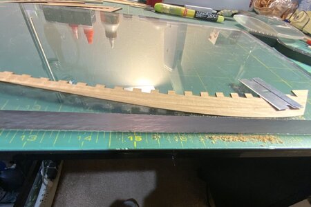
Bringing out the keel again for a few days now and taking up where I left off on that portside Part 18 (I think it's 18?) creating that very delicate rabbit. Before setting this aside I had begun that rabbit with a flat needle file, medium coarse, filing only upward from the edge. I didn't like that which is one reason I put the keel away for awhile. Today I scraped that rabbit much to my satisfaction. The single-edged razor blade worked slowly and under complete control, always scraping only toward the end grain, never into it.
alf in IowaBA76B33C-08DD-48A9-AAA4-71A4BA877FCE.jpeg
 
Back
Top