Nice description. Fitting those chocks will be the most challenging part of this build by far. If the frames aren’t right, neither is the build.
-

Win a Free Custom Engraved Brass Coin!!!
As a way to introduce our brass coins to the community, we will raffle off a free coin during the month of August. Follow link ABOVE for instructions for entering.
-

PRE-ORDER SHIPS IN SCALE TODAY!
The beloved Ships in Scale Magazine is back and charting a new course for 2026!
Discover new skills, new techniques, and new inspirations in every issue.
NOTE THAT OUR FIRST ISSUE WILL BE JAN/FEB 2026
You are using an out of date browser. It may not display this or other websites correctly.
You should upgrade or use an alternative browser.
You should upgrade or use an alternative browser.
Bomb vessel cross section - scale 3/8 or 1:32
- Thread starter Dave Stevens (Lumberyard)
- Start date
- Watchers 16
- Joined
- Dec 1, 2016
- Messages
- 6,383
- Points
- 728

- Joined
- Dec 1, 2016
- Messages
- 6,383
- Points
- 728

Nice description. Fitting those chocks will be the most challenging part of this build by far. If the frames aren’t right, neither is the build.
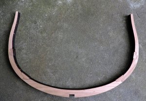
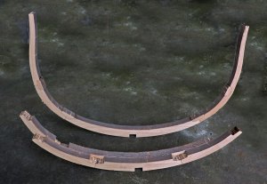
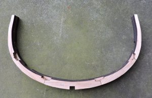
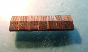
because the frame parts and chocks are cut from the same drawing they are a dead match. This means each chock fits in only one location and one way the lower chocks are slightly bigger than the upper chocks so you can not interchange them. The chock cut was offset from the drawn line which makes them a little larger as you saw in previous posts. The precision of laser cutting allows every chock to be offset or larger by the exact same amount. what this does is once you sanded one to fit each and every chock requires the exact same amount of sanding. Believe it or not it does not take a lot of fitting chocks before you get a feel for how much to remove. This is what Harold Hahn was trying to get across to builders and why he did not like the idea of "finished" material. what he was saying is to learn to get a feel of the material and learn the finer touch to model building. The final finish is in the hands of the builder and not done by machine.
This concept is along the lines of learning from a build so you can take that and apply it to the next build.
- Joined
- Dec 1, 2016
- Messages
- 6,383
- Points
- 728

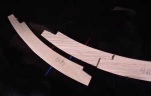
there are 2 types of frames in the model single frames which was just built and double frames. The double frame assembly is a totally different approach than what was use for the single frame. It is based on the principal the cut edges of each pieces is an exact duplicate a clone of one another. Let me show you
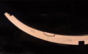
normally the first futtock would stop over the center of the keel and you would have a first futtock on either side of the frame. This style of construction is called long arm short arm, this is where the first futtock is in one piece and extends over the keel on both sides. Kind of like having 2 floor timbers
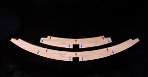
the edge pointed to with the red arrows is the exact same cut edge on both pieces as well as the edge with the blue arrows, the top piece is a clone of the lower piece with a different notch location.
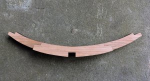
with such exact precision cutting of the parts you can lay them on top of each other and line up the edges. There is no need to build the frame on a pattern by lining up the outer edges the assembly is self alining.
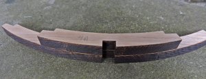
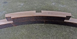
normally the first futtock would stop over the center of the keel and you would have a first futtock on either side of the frame. This style of construction is called long arm short arm, this is where the first futtock is in one piece and extends over the keel on both sides. Kind of like having 2 floor timbers

the edge pointed to with the red arrows is the exact same cut edge on both pieces as well as the edge with the blue arrows, the top piece is a clone of the lower piece with a different notch location.

with such exact precision cutting of the parts you can lay them on top of each other and line up the edges. There is no need to build the frame on a pattern by lining up the outer edges the assembly is self alining.


Last edited:
- Joined
- Dec 1, 2016
- Messages
- 6,383
- Points
- 728

Very good explanation of the construction of one frame - and good photos explaining more than thousand words - Thanks
- Joined
- Dec 1, 2016
- Messages
- 6,383
- Points
- 728

- Joined
- Dec 1, 2016
- Messages
- 6,383
- Points
- 728

- Joined
- Dec 1, 2016
- Messages
- 6,383
- Points
- 728

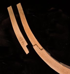
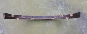
make sure the chock is set into the notch flush at the top if not you end up with gaps and spaces. By the time you have done all the chocks you skills at joinery should improve. There is enough material on the laser cut sheets you can redo the chocks 10 times over
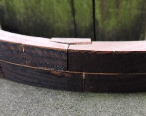
so check your fit before slapping on glue
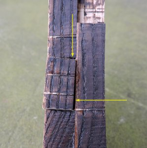

so check your fit before slapping on glue

- Joined
- Dec 1, 2016
- Messages
- 6,383
- Points
- 728

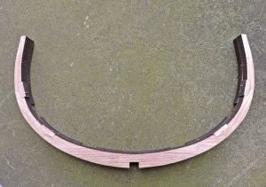
when I built the single frame I built it over the pattern on a piece of window glass. that worked great but not so much for fitting the chocks. Your working blind because you can only see the top and not the bottom of the frame. so when the frame was removed and turned over OOPS!
that's it for now, i will build all the frames and get back in a few days.
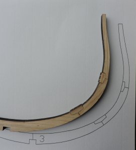
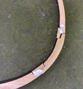
that's it for now, i will build all the frames and get back in a few days.


- Joined
- Aug 15, 2013
- Messages
- 172
- Points
- 213

I do 3D and 2D drafting I have solidworks snd draftsight on my computer at home. I am also a member of the Mystic Seaport Ship Modlers. I am a retired draftsman with 48 years experience. If you need work done we could work something out. I have experience in many facets of manufacturing. My email is lesterpalifka@gmail. Com
- Joined
- Dec 1, 2016
- Messages
- 6,383
- Points
- 728

I finished building the frames it went along with no big problems
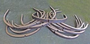
then I discovered a problem I dropped a few frames and they shattered like glass. I used a super glue because a little dab and in 10 seconds the joint bonded that made assembly go quick. joining the frame with a chock created a weak joint because of little surface between the parts.
even sanding the frames they were breaking apart so super glue is not a good idea. you can use a wood glue but in this case I did not want to glue up a frame and wait hours before moving on. for some reason super glue does not bond to itself and I did not want to sand the joints because that would mess up the fit I already had. To solve the problem and move on I doweled the chocks in place. That was a quick fix for the frames that broke and the rest I was just very careful not to break them.
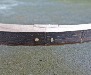
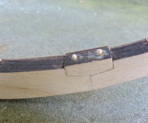


Last edited:
Always a way Dave, when you know what you are doing. Don
- Joined
- Dec 1, 2016
- Messages
- 6,383
- Points
- 728

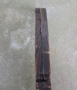
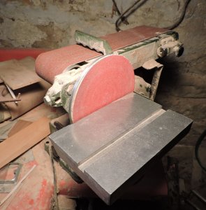
next step is sanding the frames I use three tools for this operation the first is a disk sander to do the outer edge. i also have a small 4 inch sander that falls under the "hobby" tools it is useful for small and light sanding, Sanding these frames bogged down the motor. What i use is a larger 6 inch disk and belt sander.
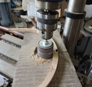
for the inside of the frames I bought a 1 1/2 inch drum sander and chucked it into my drill press.
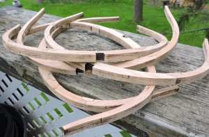
as a result of the sanding it went easy and with just a few passes a majority of the char was gone.
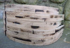
the double frames were a little harder to sand clean because of slight low areas you can see by the char left behind. I could keep sanding until all the char was removed but I did not want to sand down the entire surface.
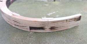
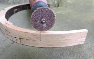
in this case what I did was to use a small disk and touched up the low spots. The first picture shows the area before sanding and the second picture shows after a touch up. i left a tiny amount in the corner. Which i will continue to clean up.
if you do not have a disk sander or a drill press for a drum sander you can sand the entire frame with just the hand power tool and a small disk. Or totally by hand I did a couple frames this way just to see if it can be done, and it can.
it depends on the philosophy of the build. What I mean by that is, I found sitting at the drill press sanding the frames was a relaxing sort of almost calming therapeutic thing. Model building should be a positive experience a Zen moment in time.
Sometimes for me it is more a rush to get the job done for things like this build log it is about getting the log done and moving on. The model is nothing but a prop used in the log.

for the inside of the frames I bought a 1 1/2 inch drum sander and chucked it into my drill press.

as a result of the sanding it went easy and with just a few passes a majority of the char was gone.

the double frames were a little harder to sand clean because of slight low areas you can see by the char left behind. I could keep sanding until all the char was removed but I did not want to sand down the entire surface.

in this case what I did was to use a small disk and touched up the low spots. The first picture shows the area before sanding and the second picture shows after a touch up. i left a tiny amount in the corner. Which i will continue to clean up.


if you do not have a disk sander or a drill press for a drum sander you can sand the entire frame with just the hand power tool and a small disk. Or totally by hand I did a couple frames this way just to see if it can be done, and it can.
it depends on the philosophy of the build. What I mean by that is, I found sitting at the drill press sanding the frames was a relaxing sort of almost calming therapeutic thing. Model building should be a positive experience a Zen moment in time.
Sometimes for me it is more a rush to get the job done for things like this build log it is about getting the log done and moving on. The model is nothing but a prop used in the log.
- Joined
- Dec 1, 2016
- Messages
- 6,383
- Points
- 728

it is difficult to find exactly the small disks needed for a sanding job such as this so I make my own. Depending on its use i will make soft disks from thick felt to leather belts to plastic disks and rubber mats.
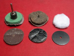
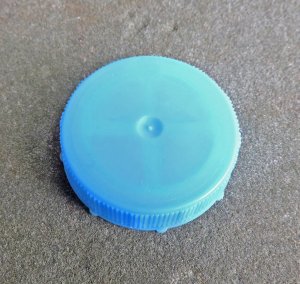
i do use bottle tops and what is nice about them is the little dimple smack dab in the center to drill a hole for the screw, i just sand around the edge and there you go a sanding disk.
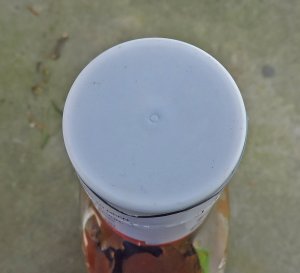
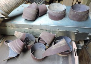
I have tried sanding paper but many times the edge hits an edge and rips or it creases. I tried to glue sand paper to the disk but that won't work on softer material and in general it is messy changing paper. to solve the problem I use sanding belts cut into disks. Three inch wide sanding belts for thickness sanders are thick and cloth backed. They will even stand up on their own without a disk backing. I have lots of this because I do not use the very ends of the sanding belts on my thickness sander so I rip off the ends and make disks from it.

i do use bottle tops and what is nice about them is the little dimple smack dab in the center to drill a hole for the screw, i just sand around the edge and there you go a sanding disk.


I have tried sanding paper but many times the edge hits an edge and rips or it creases. I tried to glue sand paper to the disk but that won't work on softer material and in general it is messy changing paper. to solve the problem I use sanding belts cut into disks. Three inch wide sanding belts for thickness sanders are thick and cloth backed. They will even stand up on their own without a disk backing. I have lots of this because I do not use the very ends of the sanding belts on my thickness sander so I rip off the ends and make disks from it.

- Joined
- Dec 1, 2016
- Messages
- 6,383
- Points
- 728

I do 3D and 2D drafting I have solidworks snd draftsight on my computer at home. I am also a member of the Mystic Seaport Ship Modlers. I am a retired draftsman with 48 years experience. If you need work done we could work something out. I have experience in many facets of manufacturing. My email is lesterpalifka@gmail. Com
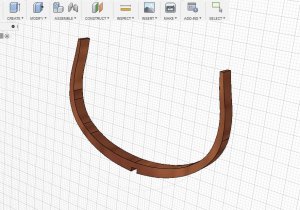
I have been using Fusion 360 a nice 3D modeling program, I quickly did one of the frames
the thing is it takes almost as much time building a 3D model as it does to build one out of wood unless you are a long time experienced user of CAD and 3D modeling.
if you have a grasp of CAD and 3D modeling FUSION 360 is not all that difficult to learn and the nice thing is it is free for hobby use. or about 500 bucks a year for commercial use
with windows having a 3D view program as part of the package a 3d file can be used as building instructions so the builder can view the structure from any angle to see how things go together.
Last edited:
Great thread, Dave.
- Joined
- Dec 1, 2016
- Messages
- 6,383
- Points
- 728

- Joined
- Dec 1, 2016
- Messages
- 6,383
- Points
- 728

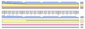
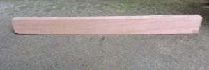
The plan set includes a pattern for making a building jig the way it works is to cut a template with notches where the frames fit. Next you need a building board the darker blue section. On this board a centerline is marked where the keel will sit. Because the outer edge of the frame is curves if the top part of the jig is set to high or to low the frames will not fit proper. The side ways distance from notch to notch on the jig is set for the exact location on the frame.
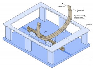
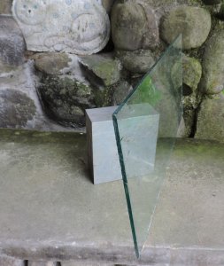
I am not going to use the suggested jig setup provided with the plan set my plan is to use a block and a piece of glass and that's all.
building in a jig is all the rage these days so this is one reason to present an alternative method. I would like to remind everyone following this log it is all about the building of a prototype and nothing more. If anyone or group want to build the model then that is where you will see different methods and finer details of the build, but not here.
- Joined
- Dec 1, 2016
- Messages
- 6,383
- Points
- 728


