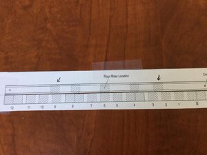
I built all 5 of the riders and set them in the hull to check that they all fit. Those are not the real colors i just tinted them so they show up in the image.
View attachment 98056
my concern was if I glued the riders in place would I be able to slip the lower section of the clamp between the rider and the hull? you can see the clamp is not sitting flat along the hull which made fitting a little difficult. Once the riders are glued in it would make it very difficult to sand the hull so the clamp would slip in place.
View attachment 98058
i found out if i put the clamp in and the riders it was sort of a wedge effect and the clamp pushed the rider up and away from the frame floor.
View attachment 98059
a little sanding of the hull was needed to insure everything fit as it should.
View attachment 98057
Once i felt confident everything would fit my approach was to set the two end riders in place with the clamp. then i can add the remainder of the riders and make slight adjustments if needed.
View attachment 98061
View attachment 98062
riders and clamps were all glued in at once. I switched from the fast setting super glue to titebond wood glue which gives me pleanty of time to make adjustments.
View attachment 98063
Dave: I've got a question. Why don't the all floor riders directly overlie the frames? The fore most rider sits partially on both frame 2 and frame 3. The aft-most rider overlies frame 9.. but "hangs over" the space between frame 9 and frame 10. The other three are symetrical over the frames. Any reason for this?T


