British Capstan circa 1777 - scale 1:16 [COMPLETED BUILD]

Joined
Jan 24, 2015
Messages
2,467
Points
638

Location
Pewaukee, Wisconsin
This will be my build log for a scratch built English Naval Capstan circa 1777, The scale is 1:16 (3/4” = 1’). Toni Levine, a name familiar to many of you, produced the plans and accompanying practicum. Toni was assisted by Mike Lonnecker, Bob Andreotti and Alan O'Neill. The result was 29 individual sheets in the planset. The model is only 6” X 6” in size without the capstan bars, so you get the idea as to the level of detail in those plans. In addition, although drawn in 1:16 scale for the most part, all measurements are given in real-life size, so scaling up or down is relatively easy to do. There are actually two versions of the practicum in the package. The first is for intermediate modelers who may own a Dremel tool and a miniature table saw. The second requires owning and knowing how to use a lathe and a mill. I don’t have a mill so I opted for the intermediate version . As is my preference, I’ll try to avoid paint or stain in the build. The bulk of the timbers will be beech, boxwood, pear , bloodwood and holly. Below is the frontspiece from Toni’s practicum showing the finished capstan.1.jpg
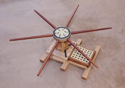
 
Hi Dave, are the six small chains on top used as lifting lugs during installation on the ship?
 
Let’s get started. The project is composed of several substructures. These include the deck framing (beams and carlings), the capstan step, the hatch and grating and the capstan itself. These can be built in any order, but it makes sense to start with the deck framing.

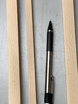
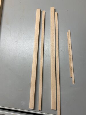
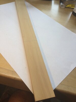
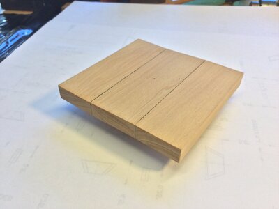
I chose beech for the deck beams and carlings. It looks very much like the oak that would have been used, but the grain/pore structure is much finer than oak. At 1:16 scale it looks about perfect. I milled up the blanks for the beams (1/2" thick X 5/8" wide) and the carlings (3/8" square).


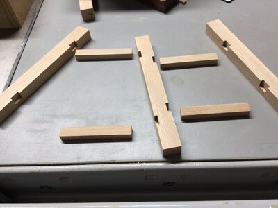
Since the model involves only a narrow portion on the centerline of the deck, no camber was designed into the beams. This makes construction much easier. The photos show the grain and the cut out blanks.


2.jpg3.jpg
 
This is a nice and interesting small project - many thanks for starting this and show us in your building log.
In which scale will you build the capstan?
 
This is a nice and interesting small project - many thanks for starting this and show us in your building log.
In which scale will you build the capstan?
The scale is 1:16, or 3/4” =1’. But all parts on the plans are labeled with their actual, real-life measurements. For example, the drumhead (where the bars that turn the capstan attach) is made of an upper and a lower part, each measuring 4” in actual thickness. So the 8” thick drumhead is 1/2” thick on the model in 1:16 scale. If we were using 1:32 scale, the 8” drumhead would be 1/4” thick on the model.
 
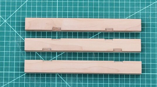
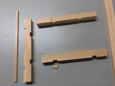
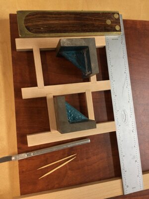
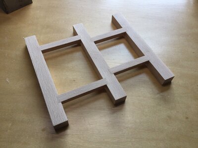
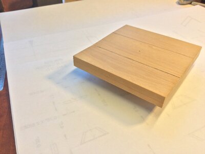
The three deck beams and four carlings are joined to form the deck, and support the hatch and grating, as well as the capstan step. The practicum suggests two ways of doing this. The first is like the actual historical joinery used. The carlings fit into stopped dadoes or “blind mortises" in each beam, the upper surface of the carling being visible and flush with the deck beams. The second method is easier, if historically inaccurate. It involves making “diagonal” mortise and tenon joints as noted in the first two photos below from the practicum. Once glued together, both decks look the same.


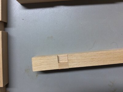
I chose a different method. After marking the mortise locations on the beams, I cut them through the full thickness of the beam, rather than leaving them stopped or “half blind". I then "filled in " the bottom of each mortise up to the bottom border of the carlings with wood to simulate a half blind joint. It the filler pieces come from the same billet of wood as the beams and carling, the “cheat" is barely visible! I've used this technique on several decks in the past.


4.jpg5.jpg6.JPG7.JPG8.JPG
 
a very clever idea - to make notches with a chisel is very time consuming
if the undersight is not visible - a very useful alternative Thumbsup
 
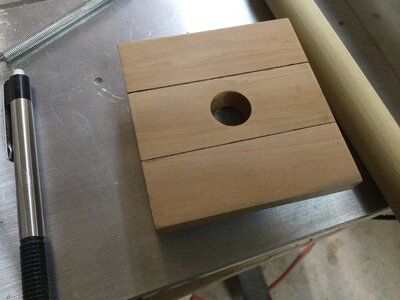
The capstan step is made of 4 parts: 3 visible, and one not visible -which holds the step between the deck beams. I chose boxwood for the step. The advanced practicum calls for the step to be constructed with 2 ship-lapped joints. I took the easy way out and used butt joints. The joints between the step parts were “caulked” with black acrylic paint. Bolt heads and a hole for the capstan barrel will come a little later.


11.jpg12.jpg13.jpg
 
In the exact center of the step is a hole for the capstan barrel. This is invisible on the final model but it allows the capstan to rotate. The best way to bore the hole is with a Forstner bit. The plans call for a 11/16” hole. I don’t have an 11/16" Forstner bit so I used a 5/8" bit instead. Worked fine!

14.jpg
 
In the exact center of the step is a hole for the capstan barrel. This is invisible on the final model but it allows the capstan to rotate. The best way to bore the hole is with a Forstner bit. The plans call for a 11/16” hole. I don’t have an 11/16" Forstner bit so I used a 5/8" bit instead. Worked fine!

View attachment 293542

Good evening Doc, I like it so much, cleanliness and precision makes the difference, Congratulations
 
Thanks, Frank!
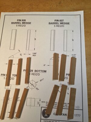
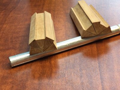
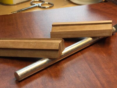
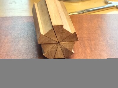
After the capstan location was defined by the hole, construction of the barrel began. The barrel is the most important part of the model because it established the shape of the capstan, sets the angles and spacing of the whelps and determines the location of the chocks. In the advanced version of the model, the capstan barrel is, for the most part, a 10 sided polyhedron with each face being 36 degrees. This is easy to produce with a mill. For those without a mill, we make 10 “orange slices" of two different sizes( 32 degrees and 40 degrees) for the ten faced polyhedron. These are then glued together radially. This is easier to understand from looking at the photos than it is from my explanation! The result is a ten-faced barrel with every other face recessed to fit the whelps.


15.jpg16.JPG17.JPG18.JPG
 
Thanks, Frank!
After the capstan location was defined by the hole, construction of the barrel began. The barrel is the most important part of the model because it established the shape of the capstan, sets the angles and spacing of the whelps and determines the location of the chocks. In the advanced version of the model, the capstan barrel is, for the most part, a 10 sided polyhedron with each face being 36 degrees. This is easy to produce with a mill. For those without a mill, we make 10 “orange slices" of two different sizes( 32 degrees and 40 degrees) for the ten faced polyhedron. These are then glued together radially. This is easier to understand from looking at the photos than it is from my explanation! The result is a ten-faced barrel with every other face recessed to fit the whelps.


View attachment 293601View attachment 293602View attachment 293603View attachment 293604
Thanks for answering me Doc, if you need anything I'm available
 
Thanks, Don!

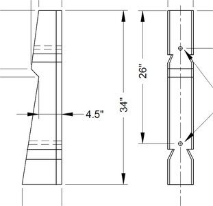
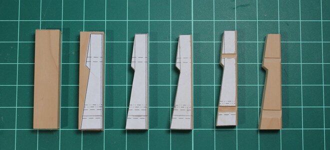
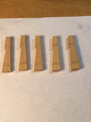
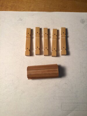
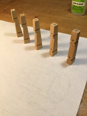
All five whelps are identical and they sit on the “recessed” faces of the barrel polyhedron. The first step is to cut out five blanks for the whelps (and a couple extra) and shape their profile. I used rubber cement to glue the template pattern for each whelp to the boxwood blank. I cut them out with the scroll saw and used files, sanding sticks and a disk sander to define the final shape. There are two pair of notches on each whelp, one at the top and another pair near the bottom. These are for fitting the upper and lower chocks. It’s a custom fit, and comes a little later. The notches can be cut with a chisel, but I found a sharp X-Acto works better! The first photo is a detail of the whelps from the plans. The second shows the steps Toni used to shape the whelps. It comes from the practicum. The last photos are my whelps, with the chock bolts in place.19.jpg20.jpg21.jpg22.jpg23.jpg
 
Back
Top