Hi Carl,
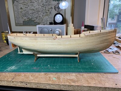
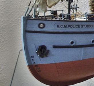
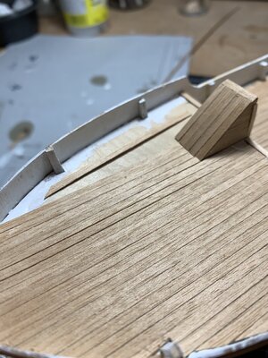
For a little more “limited” realism for my build and to help in my construction I firstly discarded the supplied rod because I wanted to rework the davit arms, similar to the actual museum St. Roch. Without digressing you will notice in the photo below the railings end at the lower part of the davits. I’ll get back to that in a bit. Also, those davit arms need to be secured adequately on the model (davit pedestal).
So I cut lengths of brass tubing to small consistent lengths for the lower part. I measured the actual height and bend of the total arms and then cut rod to length. The rod diameter was chosen to fit inside the brass tubing. However, to help secure the davit arms I allowed for a cm or so extra rod length. That extra cm protrudes past the bottom of the tubing. A hole drilled in the boatdeck allows you to secure the complete davit upright (epoxy).
Back to the railings. To secure the railing ends in an efficient manner I measured and drilled holes in the lower davit tubing before putting anything together. (Reminder to myself to buy a good model-makers vice
")
). Then when I built the railings I used a touch of epoxy to glue the ends in place into the tubes. Very fiddly to get it all aligned but patience in the key.
I made small brass rings for the head of the davit arms to give me a place to secure the blocks of the falls. I soldered them on then soldered the brass rod into the brass tubing, making sure everything was lined up for the railing lengths, heights and the davit head direction.
I didn’t reduce the davit head diameter as in the plans. Obviously more accuracy and realism is up to you but I hope this helps.
View attachment 264829