• LUCZORAMA SHIPWRECK SCAVENGER HUNT GIVEAWAY. 4 Weeks of Fun • 1 Legendary Prize ((OcCre’s Fram Ship)) • Global Crew Welcome!
    **VIEW THREAD HERE**

Building a Cutter

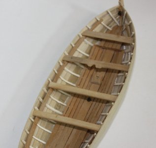
I made and added the mast step and thwarts. The square hole in the step was a simple digging with a sharp chisel. The second thwart has the protrusion for the mast support. Nothing complex.
1753870238935.jpeg

The benches at the stern are shown on some contemporary drawings and models as resting on top of the aft most thwart. But, the contemporary drawings always show the forward platform on an even plane with the forward most thwart. Looking at photos of models at RMG, the planks run athwartships, so rest on the riser. My problem was that the drawings shows the risers stopping short of the stem. That means the platform would stop short or the risers need to be extended to support a full platform.

Allan
 
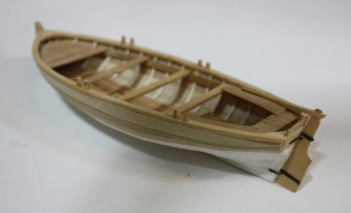
Making and adding the benches aft, platform forward, and gunwales was next. The benches aft were straight forward, using the drawing as a template. The forward platform boards were made to fit, although making a card template might have made things easier.

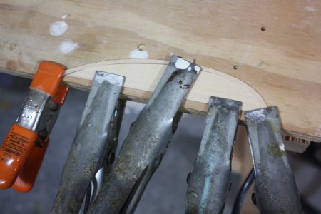
The gunwales brought up choices. Make each one in two, or three pieces or make each in a single piece and form it to fit. I chose the latter this time and it worked rather nicely. I flipped boat upside down on a piece of board that was the same thickness as the gunwales, then traced the shape on one side. I only use one side as there are tiny differences port and starboard on the boat, but with the gunwales being exact mirror images, the end result is much better in appearance.

Once the shape was traced I cut it out and clamped it to a bench. I cut appropriately sized strakes for the gunwales then soaked them in water for an hour or so. I then took one and clamped it around the form. Once secure it was dried with a hot air gun. It held its shape very well and the second gunwale piece was given the same treatment.

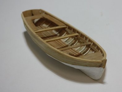
They were then glued to the boat with relative ease.

Allan

1754129869215.jpeg
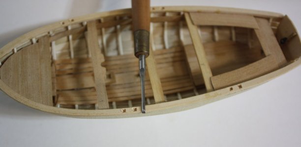
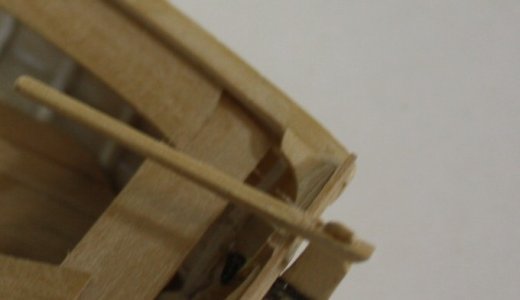
I penciled in the location of the tholes on the gunnels. The tholes are a bit tricky as in this case, they are slotted to take washboards.
1754129912488.jpeg
 
The holes in the gunwale for the tholes were made with a small chisel. Pretty straight forward but at our scales it may be easier to drill a hole in the gunwale and use a round peg in the thole once the thole is made. Note the thole holes are offset for each thwart as the cutter was single banked.

1754613817147.jpeg

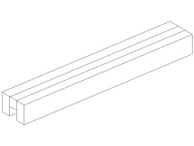
The tholes are grooved to take the wash boards whenever the coxswain would call for them to be put in. Making the groove the exact same breath as the thickness of the washboards in a solid thole is possible but not easy. I decided to make the tholes from a lamination that has the middle layer the same thickness as the washboards. Once these were made the seam on the solid side where the oars went cannot be seen and it is all but invisible on the top of the tholes.

The drawing is just a basic sketch of how I made the stock for the tholes.
1754614097109.jpeg

The tholes are fit into the openings with a dot of glue. I prefer PVA in general, and for this, it really was good in that if the thole was not perfectly in line in all axis, I could maneuver before the glue cured.

1754614234880.jpeg
 
The following picture shows four of the six washboards in place. I hope someone can help me here. I searched high and low but cannot find any information based on contemporary sources that show how the washboards were secured at the transom or at the bow. I am guessing there may have been additional tholes but I am not at all sure. In the end I will leave the washboards off the model, but if anyone has information on how these were secured at the bow and stern that would be great. The washboards were slid into place, not bolted or otherwise permanently fixed so not a simple glue or bolt in place situation.
TIA
Allan

The boards at the bow in the photo below are simply set against the stem. None of them are glued in place, just sitting temporarily.
1754662111070.jpeg

1754662145590.jpeg
 
The breasthook and transom knees were made after first making templates with card stock. These were then test fit and the breast hook template was modified at the bow then used to make the part. The knee template was an easy fit as they matched the plans.

Allan
1754662372811.jpeg
1754662394712.jpeg
 
The rudder was only 7/8" thick, so at this scale of 1:36, .024" (0.6mm). There was no way a tiller would go into the rudder, but rather the tiller would have to fit onto the rudder. Once the tiller was shaped I used a drill with a diameter that was just over the thickness of the rudder and drill several holes in line then finished it into a slot with a scalpel. The pintles and gudgeons are brass as I had no copper the right thickness handy. I have used construction paper in the past and it works well and is easier. The pintles and gudgeons were epoxied to the rudder and hull then the rudder assembly epoxied to the transom and stern post. I thought about making working parts so the rudder could turn, but at this size, that thought lasted about 30 seconds and faded gently away. Old eyes and not so steady hands have changed my decision making process. :rolleyes:

Allan

1754826401192.jpeg

1754826537785.jpeg
After seeing the close ups, there are some cleanup spots needed, but nothing major. Taking photos is a love/hate thing for me, but it does help find the tiniest of things that need to be fixed.
 
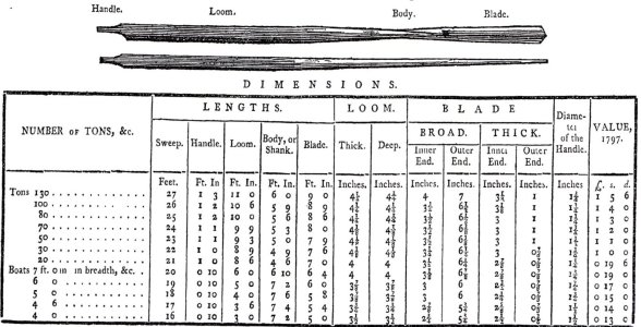
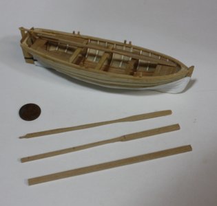
The oars are next. She was single banked with four thwarts so would have had two oars port side, two oars starboard. I cut some strips 0.17"X0.10" (about 4.5mm X 2.5mm) to start, then used the dimensions given by Steel. 1754915203644.jpeg
One thing that was a little troubling was the loom. The dimensions indicate it was square, but the drawing he includes gives a round appearance. I have two copies of the scantlings and one indicates the loom was indeed square which makes no sense to me if the oarsmen rotated the oar during a cycle. A square loom on the gunwale would not rotate well and eventually wear to a rounded shape anyway. The photos below show a square loom but I am debating on changing this to round. Thoughts anyone?

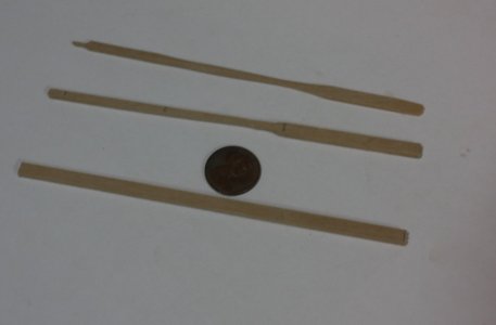
The oars below show the blank stock, initially sizing, then final rounding, blade flattening, etc. In keeping with the hand tools only idea, LOTS of scraping and finish sanding using sanding sticks.

Allan

1754915805556.jpeg
1754915784519.jpeg
 
Last edited:
The dimensions indicate it was square, ...

Here's my theory, FWIW. All but the very first oar has equal loom dimensions in both thickness and depth. I would imagine that one loom to be oval in cross section while the rest are round. What is interesting to me, is that one would assume that the thickest portion would be perpendicular to the flat of the blade, thereby reducing weight but also making the loom strongest in the dimension that would receive the most force i.e. pulling the blade through the water. The illustration, however, belies that, so your guess is as good as mine.
 
So tell me what you really think :) :)
Thanks Draft Brew If I write Draft Be_r the emoji pops up. How can this be avoided?
Haha! ‘Ask a simple question, get a simple answer’ seems to be the exception rather than the rule on SoS! ROTF

I don’t think there is a way to prevent the beer icon from showing up, so you can call me whatever you like. Most folks just use Nama for shorthand. :D
 
Back
Top