CNC Machining of Composite Wood at 1:65 Scale

Joined
May 1, 2023
Messages
115
Points
113

Hi, colleagues!

Over the past few days, I have been troubleshooting an issue with my CNC machine. Finally, I discovered the culprit - one of the power supplies was experiencing undervoltage. Unfortunately, this led to a spoiled future part of the ship model. However, it also provided me with a better understanding of the limitations of CNC processing when working with composite wooden materials.

The experience appeared to be so valuable to me that I have decided to share it with you.

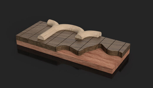
So. I've decided to upgrade the front wall of the admirals' cabin. Scale 1:65. Instead of just using planks, I decided to create a layered structure using veneer at the bottom, walnut planks in the middle, and pear wood on top. The idea is that after CNC machining, the relief parts of the wall will remain made of pear wood, while the rest of the pear wood will be machined out, revealing the walnut planking.

The pie should be like this (the concept, not a real part):
2023-06-07_231736.jpg

I designed a model in Fusion360. It took me some time :)
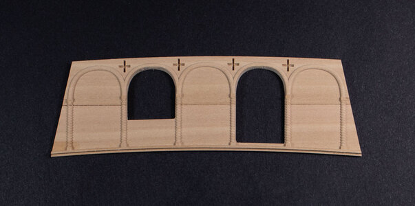
And even made a prototype - so far just form pearwood (no composite yet):
MVV_5756-2.jpg

The result appeared fine to me. Therefore, I decided to proceed.

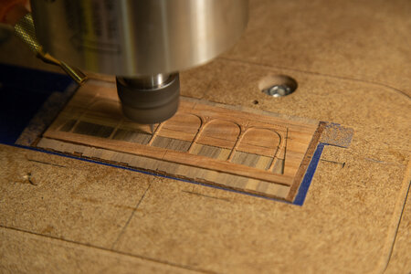
I made the material by gluing all the layers together and started machining.
At that time, the program (g-code) was conservative, too long, and not optimal.
Despite this, everything was going well, and I believed it would continue in the same manner.

MVV_5738.jpg

However, the power supply suddenly malfunctioned.
Between the power failures, I decided to reset the zero point but made a mistake in the process.
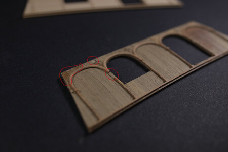
As a result, the walnut planks were cut too deeply, and in some areas, they were completely removed.

Furthermore, due to the power supply failures, the mill stopped a couple of times, causing the spindle to descend uncontrollably.
Consequently, you may notice a hole (with putty applied) created by the uncontrolled spindle.

Additionally, part of the pearwood column was broken, possibly due to the peeling of the walnut plank or insufficient glue between them.
MVV_5757.jpg

In general, I found the concept of using a composite material appealing. And perhaps, I will continue to explore it further. However, due to various reasons and issues, for this time, I have decided to take a simpler approach. I have returned to the "just pearwood" concept. But after another unsuccessful experiment, I decided to reinforce the material by gluing a veneer on the bottom side.

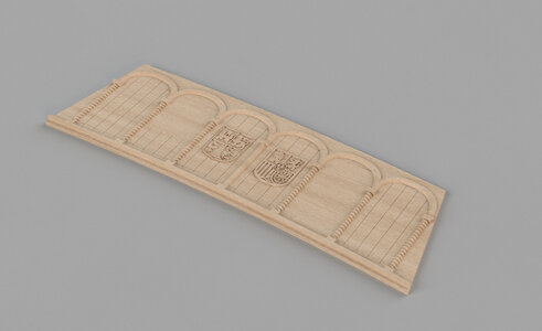
I have also made some minor changes to the design, including the addition of fake planking and a couple of shields on the wall.
These additions were made to incorporate more intricate details.
Below version represents the final model:
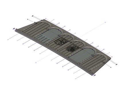
2023-06-07_222924.jpg

The rendered version:

2023-06-07_223831.jpg

This time machining went well, and here is the result:
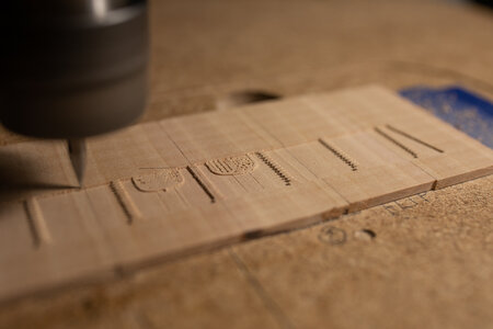
MVV_5750.jpg

MVV_5760.jpg

MVV_5752.jpg

You may notice some "chips" on the curved surfaces, but they can be easily removed with a brush.
For the main tool, I used a 30° engraver with a 0.1mm end.

My conclusion:
In the end, I am pleased with the outcome.
Utilizing a CNC machine with a 0.1 mm engraving tool can yield remarkably sharp and precise details, even at a 1:65 scale.
I'm going to continue my experiments :)
Have a nice day!
 
Dear
Rob444, Fish&Chip, albertmary, lakedaisy, KeithLyall, shota70, Kevin the Lubber, WDO, Jeffrey Modell!
Thank you all for your kind words. They inspire me to continue with further experiments :)

Here are some progress steps - the wall needs windows and a door.
Additionally, the door requires a door handle (made of brass wire, 0.3 mm thick).

Изображение WhatsApp 2023-06-11 в 12.37.27.jpg Изображение WhatsApp 2023-06-11 в 12.21.18.jpg

I am working on other details, facing small problems, and searching for solutions.
Hopefully, soon I'll have more to share with you and seek advice here.

Wishing you the best possible day :),
Max
 
Last edited:
Dear
Rob444, Fish&Chip, albertmary, lakedaisy, KeithLyall, shota70, Kevin the Lubber, WDO, Jeffrey Modell!
Thank you all for your kind words. They inspire me to continue with further experiments :)

Here are some progress steps - the wall needs windows and a door.
Additionally, the door requires a door handle (made of brass wire, 0.3 mm thick).

View attachment 379150 View attachment 379151

I am working on other details, facing small problems, and searching for solutions.
Hopefully, soon I'll have more to share with you and seek advice here.

Wishing you the best possible day :),
Max
wow, amazing work, well done Okay Exclamation-Mark Speechless
 
Dear
Rob444, Fish&Chip, albertmary, lakedaisy, KeithLyall, shota70, Kevin the Lubber, WDO, Jeffrey Modell!
Thank you all for your kind words. They inspire me to continue with further experiments :)

Here are some progress steps - the wall needs windows and a door.
Additionally, the door requires a door handle (made of brass wire, 0.3 mm thick).

View attachment 379150 View attachment 379151

I am working on other details, facing small problems, and searching for solutions.
Hopefully, soon I'll have more to share with you and seek advice here.

Wishing you the best possible day :),
Max
Perfect project with perfect results, congratulations. Thanks for sharing
 
Hi, colleagues!

Over the past few days, I have been troubleshooting an issue with my CNC machine. Finally, I discovered the culprit - one of the power supplies was experiencing undervoltage. Unfortunately, this led to a spoiled future part of the ship model. However, it also provided me with a better understanding of the limitations of CNC processing when working with composite wooden materials.

The experience appeared to be so valuable to me that I have decided to share it with you.

So. I've decided to upgrade the front wall of the admirals' cabin. Scale 1:65. Instead of just using planks, I decided to create a layered structure using veneer at the bottom, walnut planks in the middle, and pear wood on top. The idea is that after CNC machining, the relief parts of the wall will remain made of pear wood, while the rest of the pear wood will be machined out, revealing the walnut planking.

The pie should be like this (the concept, not a real part):

View attachment 378432

I designed a model in Fusion360. It took me some time :)
And even made a prototype - so far just form pearwood (no composite yet):

View attachment 378449

The result appeared fine to me. Therefore, I decided to proceed.

I made the material by gluing all the layers together and started machining.
At that time, the program (g-code) was conservative, too long, and not optimal.
Despite this, everything was going well, and I believed it would continue in the same manner.


View attachment 378430

However, the power supply suddenly malfunctioned.
Between the power failures, I decided to reset the zero point but made a mistake in the process.
As a result, the walnut planks were cut too deeply, and in some areas, they were completely removed.

Furthermore, due to the power supply failures, the mill stopped a couple of times, causing the spindle to descend uncontrollably.
Consequently, you may notice a hole (with putty applied) created by the uncontrolled spindle.

Additionally, part of the pearwood column was broken, possibly due to the peeling of the walnut plank or insufficient glue between them.

View attachment 378433

In general, I found the concept of using a composite material appealing. And perhaps, I will continue to explore it further. However, due to various reasons and issues, for this time, I have decided to take a simpler approach. I have returned to the "just pearwood" concept. But after another unsuccessful experiment, I decided to reinforce the material by gluing a veneer on the bottom side.

I have also made some minor changes to the design, including the addition of fake planking and a couple of shields on the wall.
These additions were made to incorporate more intricate details.
Below version represents the final model:

View attachment 378457

The rendered version:

View attachment 378459

This time machining went well, and here is the result:
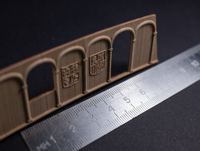
View attachment 378460

View attachment 378461

View attachment 378462

You may notice some "chips" on the curved surfaces, but they can be easily removed with a brush.
For the main tool, I used a 30° engraver with a 0.1mm end.

My conclusion:
In the end, I am pleased with the outcome.
Utilizing a CNC machine with a 0.1 mm engraving tool can yield remarkably sharp and precise details, even at a 1:65 scale.
I'm going to continue my experiments :)
Have a nice day!
wow. what a great idea!
 
Hi, colleagues!

Over the past few days, I have been troubleshooting an issue with my CNC machine. Finally, I discovered the culprit - one of the power supplies was experiencing undervoltage. Unfortunately, this led to a spoiled future part of the ship model. However, it also provided me with a better understanding of the limitations of CNC processing when working with composite wooden materials.

The experience appeared to be so valuable to me that I have decided to share it with you.

So. I've decided to upgrade the front wall of the admirals' cabin. Scale 1:65. Instead of just using planks, I decided to create a layered structure using veneer at the bottom, walnut planks in the middle, and pear wood on top. The idea is that after CNC machining, the relief parts of the wall will remain made of pear wood, while the rest of the pear wood will be machined out, revealing the walnut planking.

The pie should be like this (the concept, not a real part):

View attachment 378432

I designed a model in Fusion360. It took me some time :)
And even made a prototype - so far just form pearwood (no composite yet):

View attachment 378449

The result appeared fine to me. Therefore, I decided to proceed.

I made the material by gluing all the layers together and started machining.
At that time, the program (g-code) was conservative, too long, and not optimal.
Despite this, everything was going well, and I believed it would continue in the same manner.


View attachment 378430

However, the power supply suddenly malfunctioned.
Between the power failures, I decided to reset the zero point but made a mistake in the process.
As a result, the walnut planks were cut too deeply, and in some areas, they were completely removed.

Furthermore, due to the power supply failures, the mill stopped a couple of times, causing the spindle to descend uncontrollably.
Consequently, you may notice a hole (with putty applied) created by the uncontrolled spindle.

Additionally, part of the pearwood column was broken, possibly due to the peeling of the walnut plank or insufficient glue between them.

View attachment 378433

In general, I found the concept of using a composite material appealing. And perhaps, I will continue to explore it further. However, due to various reasons and issues, for this time, I have decided to take a simpler approach. I have returned to the "just pearwood" concept. But after another unsuccessful experiment, I decided to reinforce the material by gluing a veneer on the bottom side.

I have also made some minor changes to the design, including the addition of fake planking and a couple of shields on the wall.
These additions were made to incorporate more intricate details.
Below version represents the final model:

View attachment 378457

The rendered version:

View attachment 378459

This time machining went well, and here is the result:
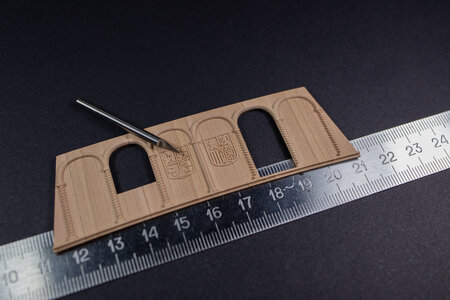
View attachment 378460

View attachment 378461

View attachment 378462

You may notice some "chips" on the curved surfaces, but they can be easily removed with a brush.
For the main tool, I used a 30° engraver with a 0.1mm end.

My conclusion:
In the end, I am pleased with the outcome.
Utilizing a CNC machine with a 0.1 mm engraving tool can yield remarkably sharp and precise details, even at a 1:65 scale.
I'm going to continue my experiments :)
Have a nice day!
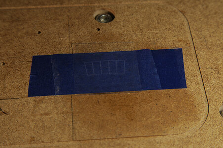
Hello. Quick question. Do you use two sided tape to hold the piece down on the machine's work surface?
 
Hello. Quick question. Do you use two sided tape to hold the piece down on the machine's work surface?
No,
I could not find some “right“ two-sided tape. All I found keeps the detail well, but the adhesion is so good that I can’t remove the tape from the detail after work, or, at least, it is not easy. The result - thin detail gets broken when being removed.

I use two one-sided tapes with a CA glue in between. At least the adhesive on this tape is “less adhesive” and provides a good balance between keeping the detail and and easiness of removal.
Sounds like you have a good solution. There is a thing called 'poster tape' that is double-sided and less sticky. But these parts may be too fragile for even that.
 
Well, today my story took an interesting turn.
It's no longer about wooden composite materials; now it's about plastic, specifically plexiglass. But in order not to produce a lot of threads, I decided to write here.

We all know that plexiglass melts easily and has low thermal conductivity, making it challenging to work with.
Despite the difficulties, I decided to give it a try using a 30° engraver with a thin end measuring only 0.1 mm.
Due to the scale of the details I'm currently working with, using a larger tool was not an option.
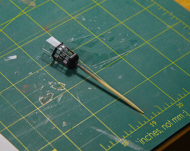
For the Lantern glass, I used plexiglass 0.2 mm thick, and for cabin windows - 0.4 mm.

To prevent excessive melting, I needed a cooling solution for both the tool and the material. Simply using air proved to be insufficient based on my previous experience. I thought that using some liquid might be a viable idea. However, using water alone was not ideal due to its poor adhesion to organic materials, and it could potentially damage my MDF wasteboard. Fortunately, during the COVID times, I happened to have a small spray bottle containing a mixture of water and alcohol. To enhance the cooling effect, I added more alcohol to the mix and sprayed it onto the plexiglass while machining.

The spindle speed was 12000 RPM.

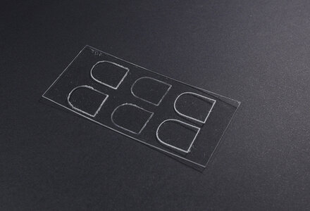
I must say, the results were quite satisfactory. Although the cutter didn't cut all the way through due to some melting, both the tool itself and the cutting lines remained clean. They were clean enough to meet my expectations. You can see the results in the pictures below.

MVV_5855.jpg


MVV_5850.jpg

The tool remained absolutely clean!!!
MVV_5863.jpg

Although it is not completely cut through, now I have clear lines to cut. I used small scissors to finish:)
MVV_5868.jpg

MVV_5874.jpg

Do you have a similar experience? How do you cut plexiglass when necessary?
Definitely, for this thickness, the usual knife is always an option. But in this case, I wanted more preciseness, especially for the Lantern.

Have a nice time of the day,
Max
 
Back
Top