Computer Aided Drafting

Joined
Aug 1, 2014
Messages
253
Points
128

Location
Tennessee
I had run across a few threads back when I was active. This was maybe 3 years ago. I tried using the search feature at the top of this site, but CAD is too short and Computer Aided Drafting failed to produce any results for me. Do any of you have links to using CAD to work with existing plans or to create plans for model ship building? I have a student copy of Autocad 2020 for my online class I am currently taking and trying to relearn the application. I used to use an older version of Autocad and also Bentley Microstation way back.
Thanks,

Jeff
 
Hi Jeff
If you have done autucad before, it really doesn't change much from year to year. Oh yes some wiz bang kid comes up with placing the , fly outs as I call them, or where some features are in a different position than what you maybe used to.
I started just after the 14 version and finally settled at believe it at Autocad version 2014.
It is no different as I said except just icons and flyouts in different positions.
I am sure there are many members who use or have used cad that can help you along the way.
Dave
 
I guess what I am looking to learn how to do, is to locate some drawings or plans and then be able to draw them up using Autocad. I am looking online now for some decent drawings with measurements that I can take to learn with.
Jeff
 
Jeff,

Here's the way I did it.

The Danish national archives has a ton of plans you can download for free. The files are large photoshop images. You can get them here.

https://www.sa.dk/ao-soegesider/da/other/index-creator/40/3353816/17149179

Find a body plan "A 100" is a body plan.

Use the "image" command to insert the image into autocad. Then scale it up to whatever you want to work with. You can scale it to 1 unit is a foot or to inches. I scaled mine to 1:48 because that is what I wan't to build my model in. Of course it doesn't matter other than if you want to think about what wood stock you're using for each part etc.

Then go to this site


Download the US Brig Eagle (1814) Practicum. It's a pdf file that does a good job of explaining how the plans are layed out and how to turn them into something that makes sense.
 
Hi

also you can look around in these categories too,lots of links to ship plans and drawings


Do any of you have links to using CAD to work with existing plans or to create plans for model ship building?

I have a collection of plans that you can import into CAD for tracing, also have a collection of DWG plans you can use to get started with developing a set of drawings from.

let us know what you want to do and we will do our best to help you out
 
Thank you for that Dave.

My past work with CAD involved taking some existing drawings and adding or modifying road layout, overhead cabling and other infrastructure. I have also taken hand drawn sketches with measurements and created a CAD of those. I am trying to use my educational version of Autocad 2020 as I am taking an online class from a nearby university. I am unable to locate the raster tools that are discussed in some Autodesk forums. So, I have emailed customer support for assistance. I am open to any assistance from all you you regarding this. I was able to get the .jpg inserted into a layer and have been working on scaling it. But, my next step was to convert the raster to vector to modify. I do not look forward to tracing all of the body lines, but that maybe something I should learn to do anyway.

Thank you again for all your support.

Jeff
 
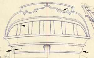
it is a good idea to trace a raster image and not use the original because just about every original drawings of ships are distorted as you can see on this tracing of a stern. i traced the left side and mirrored it to the right side you can see where the arrows are pointing the original drawing is off.

stern tracing2.jpg
 
There's also a second problem with just converting the drawings from raster to vector, and that is the consideration of sizes of wood your going to use to build the model. Unless your going to laser cut or mill every piece of wood to match the size the computer produces you'll need to adjust the sizes of things as you design the model plan. No raster to vector program is going to produce nice even 1/4" thick keel, or a 1/16" rail cap etc.
 
There's also a second problem with just converting the drawings from raster to vector, and that is the consideration of sizes of wood your going to use to build the model. Unless your going to laser cut or mill every piece of wood to match the size the computer produces you'll need to adjust the sizes of things as you design the model plan. No raster to vector program is going to produce nice even 1/4" thick keel, or a 1/16" rail cap etc.

this is true converting a drawing will not work as a set of modeling plans.

i consider the original as nothing more than an artists rendition of a ship and NOT as working plans.
 
There is nearly as much work in drawing up working model plans/designs as in actually building a model. It is then another entire process/skill all together to fabricate parts based on computer created plans. Unless the person has significant computer experience, I would not suggest it for a novice unless you decide this to be your primary hobby (i.e. versus building kits).

Just my two cents, speaking from experience.
 
Mike and Jeff
I have spent two years drawing up plans. It depends on what you want to draw and what you include.
As an example decks, and x section basics to adding frames and other details.
If you just want the plans so you can build it yourself you can take some short cuts, But if its for others there is a lot more.
but lets not forget the I did it factor. A lot of satisfaction and what I learned is its not perfect but I did it.
Dave F.
 
Dave, for lack of better terms, how did you get the "french curves" done like that in CAD.
 
Just for another option. I use the "polyline" in Autocad to draw curves like that. In Autocad once you start a polyline command you can type "A" to draw an arc tangent to the last entity. Or as the first entity you just have to type "S" for the second point of the initial arc. Once you are drawing an arc you can type "S" for the second point of the next arc if you don't want it to be tangent and when you want to go back to a straight line you just type "L" while still in the active polyline command. It's worth playing with if you use Autocad, or your program has the same functionality.

Like others on here, I've been using Autocad since version 9, and there's about 10 different ways to do about everything. Funny thing is for 2d drafting there really isn't all that much different between Autocad 9 and 2019 other than the windows environment and a billion little icons. I still type most of the commands with an alias because it's faster than picking icons or menus.
 
Back
Top