Constellation, the sloop of war c.1856 in 1:36 scale for R/C sailing

Joined
May 12, 2017
Messages
210
Points
213

Location
Maryland USA
I have a project I started back in early 1999. I'll place this "build log" for it here, but first we need to go back in time and get caught up...

I've built working model boats of all sorts, but most being smallish tended to bob like corks in Baltimore's Inner Harbor where I sailed them. I wanted to build something large that would sail like a boat. I was inspired to action by a model of the Rattlesnake I saw in back-issue of Model Ship Builder magazine, but wasn't sure what boat to build.
msb25.jpg

The hermaphrodite, or "jackass" bark was a favorite rig of mine...
Jackass.jpg

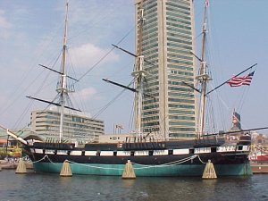
But a friend suggested a local boat that had just gone into dry-dock for restoration; the sloop of war Constellation, which the more I thought about it, the more it sounded like a good idea.
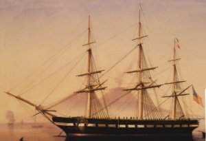
simone1856.jpg Constellation at Naples 1856 by Tomasa deSimone

I won't get into the "controversy" surrounding this boat besides saying, this vessel is not and never was a frigate by any measure. The only people that buy that story also think the world is flat. A quick summary of her history can be found Here

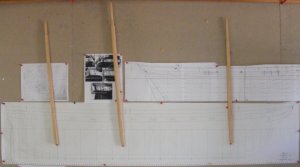
I made a visit to the National Archives in College Park Maryland and came home with her lines in 1:36 scale, her 1854 sail plan, and several other drawings of the ship, even the lines for her boats. Several drawings in their catalog were missing, such as her 1854 spar deck plan.

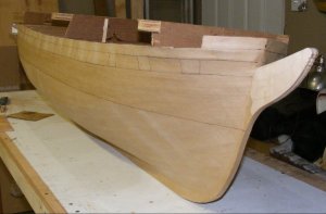
Rattlesnake was built with extended forms on a baseboard, something like Harold Hahn's method, and that's how I went about building Constellation. The forms were cut from thin plywood paneling pulled out of my house when I remodeled it, mounted on a particle-board base, also scrap from the remodel. The keel is 1/2" birch plywood.
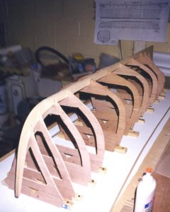
con19990218a.jpg

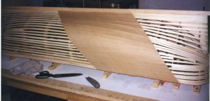
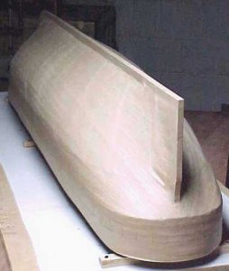
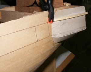
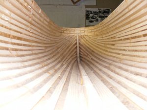
Before I started planking I came across a book by William Mowell about building the iron frigate Warrior. He battened the forms instead of planking and covered the hull in layers of brown paper packing tape, which he covered in masking tape, made a fiberglass mold from that, and laid up a fiberglass hull in that mold, the original "plug" being destroyed. This seemed like a great idea and a mold would allow me to easily make more than one hull, in fact, I decided to make three; one as the RC model, and two unrigged static models; one to be donated and the other sold, figuring a local Baltimore company would like a 5 foot hull of the Constellation in their lobby, and the money would pay for the whole project.

warrior.jpg

So off on this tangent I went...
con19990304b.jpg con19990304c.jpg con19990321e.jpg

The idea was to lay on planking and other details on the "plug" to impart things like plank lines and moldings to the mold, but there were a lot of such details not shown on anything I found at the archives, so I had more research to do. In the mean time we moved to a small farm and the plug was store under plastic in the corner of the barn.
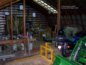
con20040816.jpg

The wife and I split up, we sold the farm and the plug went into a storage unit. I bought a house with a workshop in a separate building and in 2009 pulled the old plug out to resume work on it, a decade later.
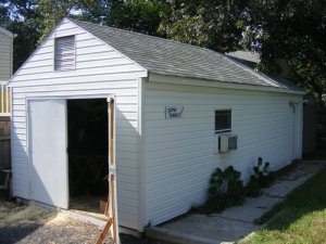
dyws20090905.jpg dyws20090105.jpg

Next up: How NOT to build a hull
 
Last edited:
Hallo Jerry, first of all a warm welcome back to the forum.....
A very interesting project you want to show us here, and thanks that you start from the beginning.
RC sailing models have their special needs and problems......I got once from Pier Books the book „William Fredericks (1874) scale journey“ for review. In this book the author is describing the built of a RC model of a 3 mast sailing ship. So I have a small insight of the problems with ballast, running rigging etc.
Is / will your model be motor forced or by wind force?
I am looking forward and will follow your log with high interest.
 
Last edited by a moderator:
Now with a proper shop, I picked up where I had left off; that is, applying planking and coppering, and other details with brown paper tape to impart those details to the eventual mold. In the meantime, the ship had been launched and returned to her dock, so I went and paid a visit to get some data, measurements, etc.
33485
I got to see how the ship didn't have typical bulwarks, but wainscotted hammock bulwarks instead.

3348333482

She mounted 10" shell guns on pivot mounts on the spar deck, one fore, one aft, and the "solid" bulwarks there were hinged to fold down, or be removed, when the guns were in action. The forward one were on the ship up until she was removed from the Navy list and went to Baltimore in 1955, and most of the original bronze hinges from them still exist.
33484
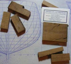
I was given a bunch of pieces of live oak removed from the ship during her restoration, which I had to figure out how to incorporate into my model.
33486

I also got to see drawings on the pivot guns and their carriages, and poke around in the darker recesses.

I had made the plug with a bulwark attached; this new information meant I had to cut the hull down as the bulwark would be built on later.
33487
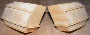
I also started fashioning the quarter galleries so they would be a part of the hull when it was cast.
33488

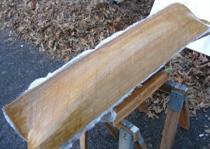
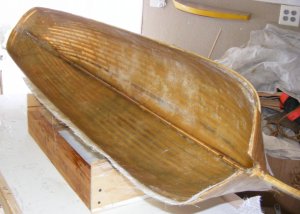
I wasn't really happy with this paper hull so I distracted myself by working on making the masts so I could mock up the controls and figure them out - I'll get into that in a later post. Eventually I gave up on making a mold and decided to just make the one hull. This is where I feel I made the wrong decision. What I should have done was strip the plug of it's paper and battens, set the forms up again, and properly plank it with wood. What I did do was lay 4 oz cloth on the outside, slush some resin and sawdust around inside to fill, somewhat, the space between the battens, and lay-up glass matting inside the hull.
33489 33490
33491 33492

So, the hull was a hull, and no longer a "plug." For better or worst, this was the model.
 
Last edited:
Moving on, I made the quarter galleries as separate parts that were held on with a screw, but would later be permanently epoxied to the hull as well. They were made from scrap pine and bass sheet.
33493 33494 33495

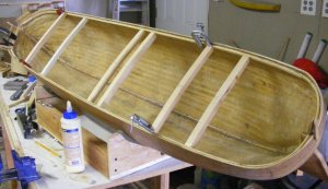
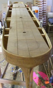
More pine, cut into strips, was glued in as the deck clamp, and a "sub-deck" of 3/16 luan plywood was cut to fit. It was later cut into 2" wide sections to help it conform to the combined sheer and camber of the deck. Deck beams were 3/4" square pine with the camber cut into them, and notched to fit the deck clamp from underneath. The thinking here was the sub-deck and beams would sandwich the clamps between them. All of this was a bit over-built than it needed to be, but that wasn't a problem.
33496 33497

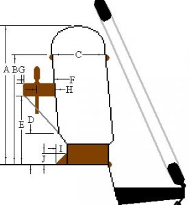
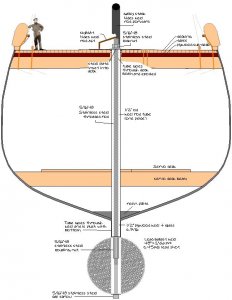
Here's a cross-section showing the structure of the deck and it's relation to the hull, as well as how the removable ballast is made and attached.
33498

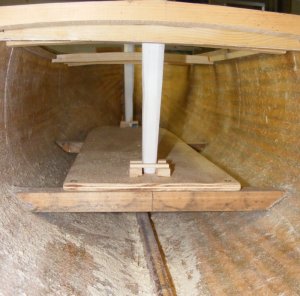
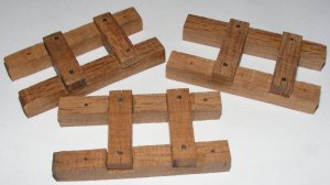
I wasn't going to model the gun-deck or any of the decks below the spar-deck, but I did need a deck below to mount the controls on, and it seemed a good place to step the masts as well. That's were I could use that live oak from the real ship - mast steps!
33499 33500

This "mechanical deck" was 3/8" plywood sitting on 1" square beams with no sheer or camber. A separate deck is mounted a bit high aft where the rudder servo and mizzen step live. In-between was where the battery would go. I built a box from aircraft plywood the battery would slide upright into, but scrapped that idea and glued in a plywood deck for it to lay down on with Velcro tabs to hold it in place.
33501
 
Last edited:
Indeed very interesting insight to your work.... great to have you here.....
 
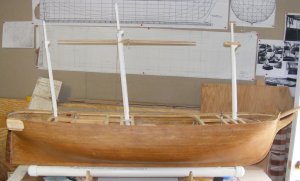
While at the lumber yard for something else, I happened across some nice looking white cedar boards and bought a couple to make Constellation's masts.
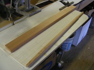
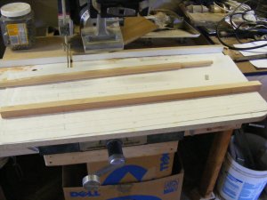
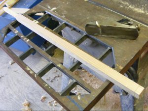
With the "mechanical deck's" position settled and where the masts would stepped now known, I knew what the "bury" for each mast would be. Each was cut to length at the correct angle for it's rake. The taper drawn and shaved to that line with a block plane. Made 8-sided, then where it is going to round, 16-sided, then rounded. The doubling was cut in, tenon for the cap, etc. Being an 1850's vessel, her masts were simpler than say, Constitution's were. The hounds are basically bolted on and banding was represented by more of the infamous brown paper tape. A front fish was added for the topmast to slide on when it's lowered.

33752 33753 33754

33755 33756


Some crosstrees and trestle trees were made, and some quickie caps from red oak that would be replaced later. I then made the topmasts now that I had somewhere for them to go.
33760 33761
 
Last edited:
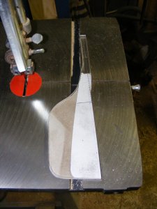
The basis for the rudder was what used in the kits by Steel, Chapman & Hutchinson
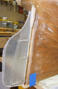
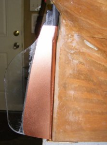
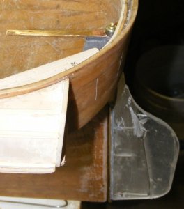
The rudder itself is Plexiglas made oversized to give it more authority under way. It's attached to a brass rod with glue and rod drifts. Thinner Plexi panels to the shape of the scale rudder on either side make the whole assembly the scale thickness of the actual rudder. A bit of maple dowel slides over the rod to make the rudder head it's scale size.
33799 33794 33795 33797
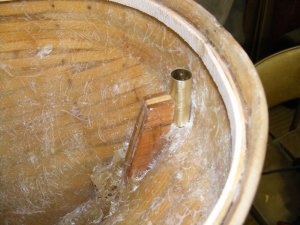
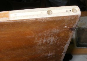
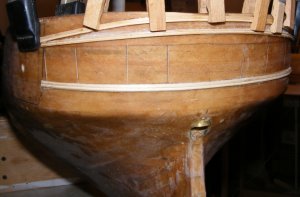
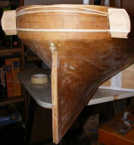
Instead of gudgeons and pintles, only the top and bottom of the rudder post/rod are secured to the model. A brass tube pokes through the counter of the hull and shows a little looking like the the curved plate on the actual ship. The dowell that's the head of the rudder fits into this tupe, but only a little bit, it stops about 1/8" in. Inside this tube is a smaller tube suspended in JB Weld epoxy. This keeps the rudder from riding up.
33791 33792 33793 33800

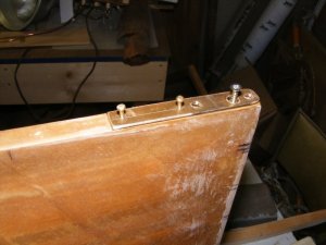
The bottom, or heel of the rudder is held by a copper plate. The keel was mortised and sealed with resin - this is critical as any water that gets into the wood will cause swelling and rot - EVERY hole in the hull is drilled over size, filled with epoxy, and then drilled to size so NO wood in the hull is exposed to water.
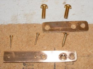
A heel plate with 5 holes, 2 of them threaded, was attached with copper wood screws and epoxy to the keel. A gudgeon plate was attached to the heel plate's 2 threaded holes with copper machine screws, so it's easily removeable as need be. A hole in the aft end of the gudgeon plate receives the bottom of the rudder post rod forming the bottom "hinge" of the rudder.

3380233801
3380333804
33798

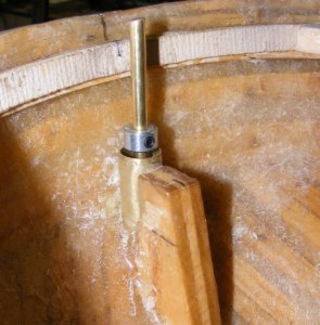
Inside, a copper tiller are was soldiered to a steel collar with a set-screw in it. It slides onto the rudder post rod inside the model.
3379633806

This is the rudder arrangement I use in all my working models. It's strong, simple, and easy to disassemble and maintain.
 
Last edited:
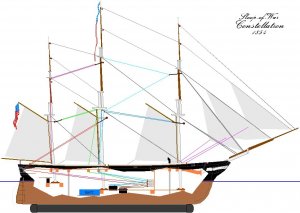
Setting up a model square rigger to actually sail by remote control isn't especially difficult, unless you're trying to maintain a scale appearance to the operation, that is, the braces attach and routed the way they did on the actual vessel, and the yards brace at something like a scale speed. There's two major geometry issues to deal with; the yard braces, and any sails that overlap each other or a stay, such as the heads'ls.

The usual way of dealing with bracing the yards is to put the widest set of arms on the brace control servo that will fit in the hull. The braces are run up to the yards and attached the same distance out from the center line on the yard as they are out from the center of the servo arm. This basically forms a parallelogram where everything moves evenly. The problem is, this isn't how the braces run on a real ship; they are run out almost at the end of the yard, out-board of the side of the hull.

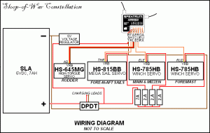
The best way to deal with this is to use a drum on a servo designed to rotate multiple times, a winch servo. I initially intended to directly control the braces for the fore and main course yards, the crossjack, and the fore and main tops'l yards. The other yards would be pulled along by the sails below them. I also intend to control the fore mast braces separately from the main and mizzen masts so I can back the fore when tacking ship.

This meant I needed two winch drums for each controlled yard for a total of 4 for the foremast and 6 for the main and mizzen. The problem is, again, geometry. The fore course yard is longer than the fore tops'l yard (measuring between the points where the braces attach. The winch rotates 3.5 times. If the drum were the same size for each yard the braces would be pulled more for the shorter yards than for the longer ones - I wanted them all to come around evenly together.

The simple answer is different sized drums for each yard, but nothing is ever simple. When the yards are squared across the hull, the braces are at their tightest. As the yard is pulled to one side, the opposite brace is fed off the winch at the same rate and goes slack. Bracing the other way the braces both go taught as the yard squares, then the paying out brace goes slack.

Slack lines on a remotely controlled model are not good. They tend to snag and catch on things, and the brace paying out could actually run off the drum and tangle. To deal with this I intended to run each brace through a block on a spring that would keep tension on each brace all the time. Initially I also planned to put some bungee else where in the circuit to be sure, but in the end I felt only the springs were needed.
34038
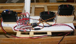
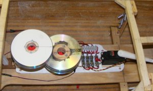
The winches would be mounted on a pallet that would fasten to the mechanical deck in the model, so the entire control system could be removed as a unit if required. They would also be offset vertically so they wouldn't interfere with each other. A set of guides would go in near the drums to make sure each brace fed on and off it's drum without crossing.
34029
3403334028

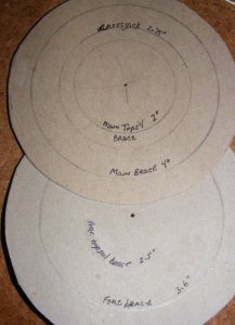
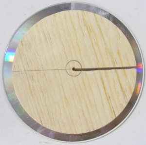
Some algebra determined what size each winch drum needed to be to move it's yard from one side to the other. The drums were 1/8" thick pine disks and the flanges were compact-discs.

340323403534036
3403434037

A typical brace would run from it's anchor point, on a stay for instance, to a block on the yard-arm, to a block in the rig turning it toward the deck, through the deck forward to a block on a spring, and to the winch. That seemed simple enough - but it was to change. ;)
34027
 
Last edited:
The main ballast would be external, bolted to the bottom of the hull. I wanted to cast a lead bar for this and even made a wood mock-up, but I never got up the courage or equipment to melt and pour a 40-50 pound lead bar.
34040
What I opted to do was pour the lead shot I had into a 2" i.d. PVC pipe. I put some smaller tubing through the pipe so the attaching bolts could pass through and leave the pipe water-tight (see the cross-section image in a prior post), glued on one end-cap, and donning my mask, glasses, and rubber gloves, poured the shot into the open end. I tamped the lead down with a pole, tapped the pipe with a rubber mallet, and actually duct-taped a vibrating sander to it, to help settle the shot as tightly as I could. I drilled a 1/2" hole in the other end-cap and glued it onto the pipe, then I continued filling it with shot while tapping and vibrating it all down. When I felt the lead was as tightly packed as it could be, I plugged the hole and the "torpedo" was done. It would up weighing 42 pounds when complete.
34042
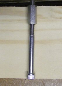
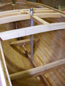
In each smaller tube a 5/16" stainless connecting nut is pressed in and a hex-head bolt and washer are screwed into it from below, with a bit of Lok-Tite to be safe. Two 5/16" stainless threaded rods go through tubes in the hull and thread into the connecting nuts in the ballast tube. On deck, they have nylon lock-bolts, but the ends of the rods have slots cut into them so they can get set with a screwdriver. The aft rod is hidden under the great cabin sky-light, and the forward rod is disguised with the galley smoke stack.
3403934041

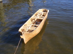
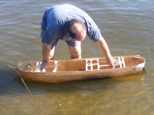
Now I was itching to put this thing in the water. On October 14th, 2009, we took my day-sailor out, and I put the model in the truck. When we got back, I put the model in the water for it's first ever float. I forgot the ballast rods, so all I could do was push it down to the waterline by hand to see if it leaked - it didn't.
3404334044

Three days later I took the model to the water again, remembering the rods, and even sticking the battery and lower masts in the hull.
3404634045

With a little over 50 pounds in her, she still floated some 2" high in the water. I knew the ballast tube wouldn't be enough to put her on her lines, in fact I wanted internal ballast I could move around inside to trim her where I wanted her to float. I estimated the finished model, ready to sail, would weight about 100 pounds.
 
Last edited:
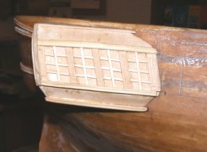
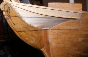
After the float I worked on the enclosed head, looking to the framing on the actual ship as a guide. My frames were made from wood from the louvers of an old shutter, and the planking is bass-wood sheet.
35863358643586535866

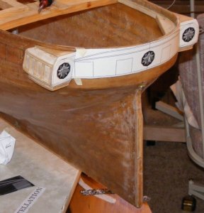
The quarter galleries were detailed with moldings and mullions
3586935871

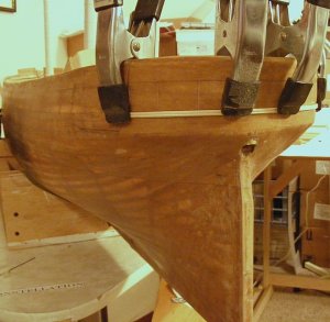
and moldings also went on the head and stern
3587235867358683587035873

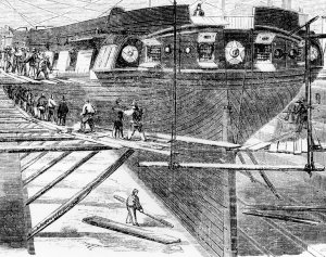
Based on a drawing of the ship in dry dock at Boston in 1859 (this is the same dry dock Constitution was just in recently).

35874
 
Last edited:
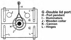
If you look back near the beginning of this thread you'll see the hull is built of battens, covered with brown paper tape and a layer of 3oz glass cloth. Inside I spread some resin around to fill between the battens and then laid a layer of glass mat laid inside to stiffen and strengthen the hull. I never intended to model the gun deck, figuring it was better for a sailing model to not have 26 1 inch holes running down the sides. In this period, the Navy used split gunports with a hole for the muzzle of the gun to be inserted into. I figured to model these, with the muzzles peeking out, and a tampion in each gun.
141CannonDrill_GunPortLids.jpg
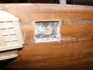
I carefully cut a gun port down to, and leaving the mat layer inside as a backing, and made a wood mock-up of the gun port lids.
con20100115a.jpg con20100115c.jpg

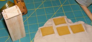
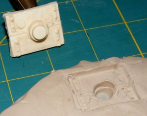
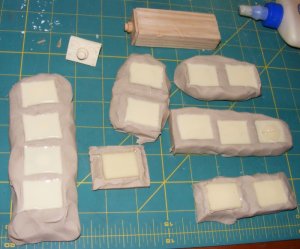
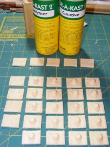
That seemed like it would do the job, so I made basically, a stamp, and pressed it into clay to mold casting resin port lids. Some little details like nuts were pressed in with an allen wrench, and a tube made the port light rims.
con20100120a.jpg con20100121a.jpg con20100121b.jpg

Again, that came out pretty good to my eye, so I went for it and cast a whole crop of pads of butter....
con20100123h.jpg con20100123i.jpg

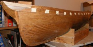
Cutting out the rest of the gunports, leaving the matt layer intact, each port lid casting was glued in with epoxy made into putty with fine sawdust so as to fill around each port lid as well as glue it in place.

con20100123j.jpg con20100210i.jpg

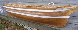
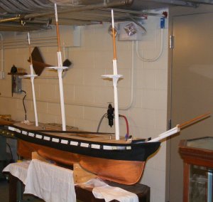
She still looked like a log to me, albeit a log with guns, but a log none-the-less. What was needed now was paint!
 
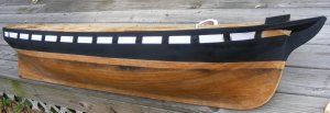
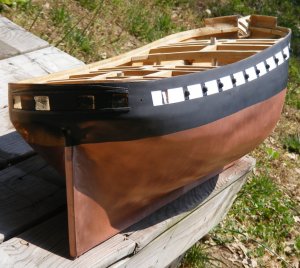
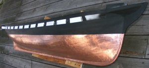
Getting some paint on her was quite the transformation. She certainly didn't look like a log any longer. I used some generic spray enamel paints and did just a quickie paint job. The bottom was Krylon metallic copper which I was going to weather a bit, but the more I thought, the more I wan't to copper the bottom.
35885358863588735888

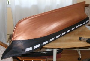
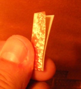
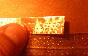
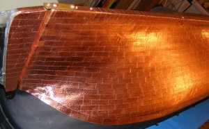
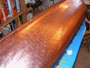
I found a place online that sold metal tapes for electrical use much cheaper than modeling suppliers charged. It's meant for outdoor use and is uncoated, It was also wider tape that's hard to find with modeling suppliers who don't deal in large scale stuff so much, if at all. It's peel-and-stick which seemed easier than trying to glue each piece. I bought three rolls figuring it would take about 2-1/2 to cover the bottom. As soon as I got it I put some on a block of wood and on a sheet of card and left it outside in the yard to "age." If you live in a country with copper coins, you've seen how copper ages. A ship's copper bottom does NOT turn green (except for sea grass) unless it's been pulled out of the water and sitting long enough to oxidize. I'm building the ship as she appeared when about 2 years old, and her copper still looked like copper in the portrait of her at Naples, not shiny and new, but not brown yet either. I figured to let the copper brown a bit naturally, then halt the process with a couple of coats of clear-coat spray.

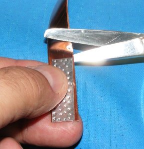
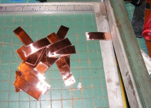
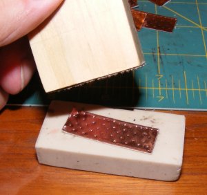
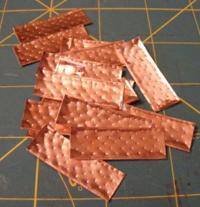
I made a pattern from a bit of sheet aluminum, including the dings for the nails. I soon had something of an assembly line making up the zillions of these plates
358933588935896358943589535890

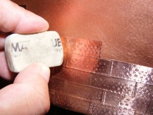
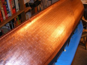
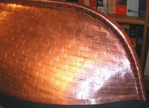
Copper on ships bottoms was nailed on with counter-sunk, flat-head, copper nails into holes pre-punched in the copper sheets. I don't know why suppliers that make "plates" for coppering a model insist that they show round headed rivet like bumps. All you should see are little circles with the slightest shoulder where each nail head is. That's the appearance I was going for here. When pressed onto the hull, the dent made with the pattern gets pushed out again and looks like a little circle.
3589135897358923589835899
 
Last edited:
It was tedious work, and tore up my finger tips working with all these little copper razors, but it really was something when it was done.
I did the starboard side, worked on making the tops for the lower masts, then coppered the port side. Then I dragged my copper-bottomed-pot down to the Naval Academy for show-and-tell in the museum workshop.
con20100623g.jpgcon20100725f.jpgcon20100801b.jpgcon20100801c.jpgcon20100812b.jpg

Here's an annoying little GIF (there's another kind?) of some of the copper going on...
con20100725.gif

And a video (caution, it may be a bit loud)
 
Last edited:
Hallo Jerry, the coppering is realy looking good.
I am looking forward to hear, how the Coppering react with water after some time sailing.....will the tape keep them at the hull, changing the color etc......???
Or will you protect the copper plates with a transparent paint?......
 
Back
Top