-

Win a Free Custom Engraved Brass Coin!!!
As a way to introduce our brass coins to the community, we will raffle off a free coin during the month of August. Follow link ABOVE for instructions for entering.
-

PRE-ORDER SHIPS IN SCALE TODAY!
The beloved Ships in Scale Magazine is back and charting a new course for 2026!
Discover new skills, new techniques, and new inspirations in every issue.
NOTE THAT OUR FIRST ISSUE WILL BE JAN/FEB 2026
You are using an out of date browser. It may not display this or other websites correctly.
You should upgrade or use an alternative browser.
You should upgrade or use an alternative browser.
Thank you!Rob,
Well done. I'm taking notes because I know some day I will do the Victory Cross-Section.
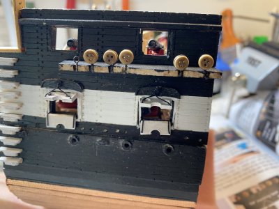
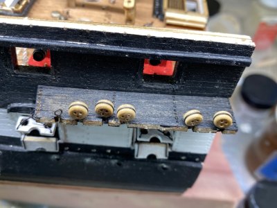
Now onto the channels and chain plates. The channels should have 6 slots cut into them for the 5 deadeyes and one eyebolt that are going to be attached to the chain plates. The picture on the instructions show it thus. In reality there are only 5 slots laser cut. You need to cut another slot inside the group of 3 slots. I did this with a small file which you can see below. Each channel was painted black and the chainplates darkened. previous build logs complained that only 10 chainplates were provided but 12 were needed. Model Expo must have heard because the provided 2 PE frets of 10 chain plates each.
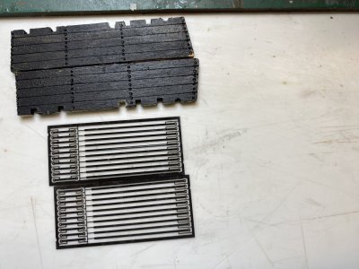
before you attach the channel to the ship make sure that the tab used to help hold the exterior wall segments together are cut away.
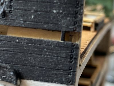
The channel is positioned so that the 4 slots are closest to the bow of the ship.
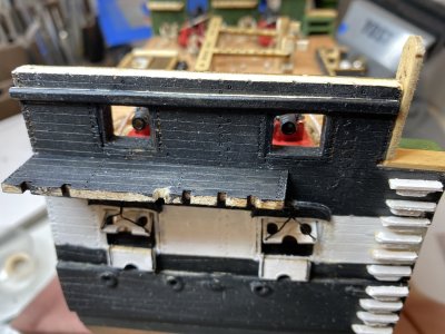

before you attach the channel to the ship make sure that the tab used to help hold the exterior wall segments together are cut away.

The channel is positioned so that the 4 slots are closest to the bow of the ship.

Last edited:
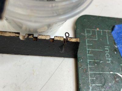
As per the instructions an eyebolt was bent into position and the "tail" was hammered flat. This was then glued into place on the channel using CA.
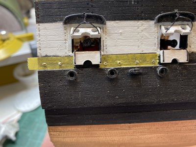
Now 1/4 inch masking tape was placed along the wales and using the dimensions provided areas were marked for holes to be drilled to hold the links.
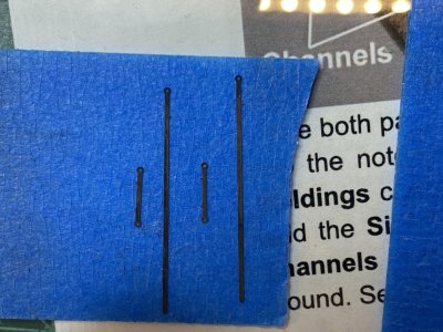
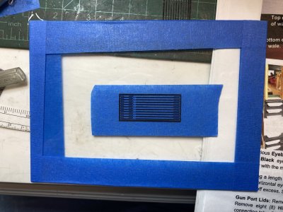
I wanted to see how the links and chain plate would fit. I thought I would show you how I cut PE (photo etch) pieces out of the supplied frets. If you try to cut these on a cutting board the pressure of the cut often distorts the piece. I have a small piece of glass (old picture frame glass). I taped the edges with masking tape and put a piece of masking tape in the middle of the frame. I cut the PE by pressing down with an Exacto blade. The masking tape gives enough "give" to help prevent the piece from flying off into the dimension of lost pieces, but does not distort the fret.
I took the link and chain plate and tried to fit them onto the ship. Once again the holes on the link and chain plate were too small to fit with any material other that the spinal needle stylets. I tried to drip them a bit larger but that just resulted in filling up the holes with metal. Does anyone have a suggestion to easily enlarge the holes? At this point I will just be using pieces of the stylet to get them in position.
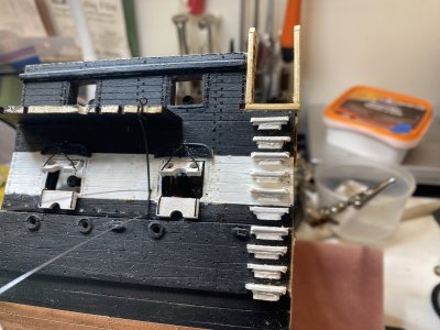

Now 1/4 inch masking tape was placed along the wales and using the dimensions provided areas were marked for holes to be drilled to hold the links.

I wanted to see how the links and chain plate would fit. I thought I would show you how I cut PE (photo etch) pieces out of the supplied frets. If you try to cut these on a cutting board the pressure of the cut often distorts the piece. I have a small piece of glass (old picture frame glass). I taped the edges with masking tape and put a piece of masking tape in the middle of the frame. I cut the PE by pressing down with an Exacto blade. The masking tape gives enough "give" to help prevent the piece from flying off into the dimension of lost pieces, but does not distort the fret.

I took the link and chain plate and tried to fit them onto the ship. Once again the holes on the link and chain plate were too small to fit with any material other that the spinal needle stylets. I tried to drip them a bit larger but that just resulted in filling up the holes with metal. Does anyone have a suggestion to easily enlarge the holes? At this point I will just be using pieces of the stylet to get them in position.

I made the deadeyes that fit on the channels. As suggested by the instructions I stropped them using the provided 27 gauge wire. The deadeyes provided are very nice. Much better than the blocks supplied. I took about 1.5" of the wire and made it into a arch that the deadeye would fit into.
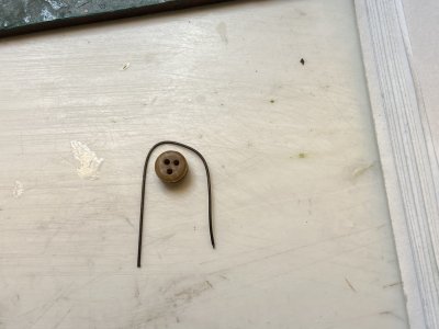
They were then wrapped by hand making sure that one of the holes of the deadeye faced the tail of the wiring.
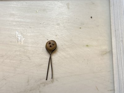
They were then twisted tightly with a pair of needle nose pliers making sure a hole was facing the tail.
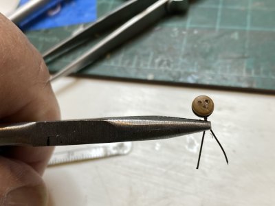
Then tail was then hammered flat.
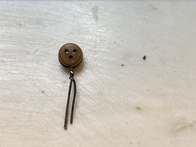
The dead eyes were then placed in the slots of the channel and the tail bent and using pliers pressed onto the back of the channel that had a drop of CA on it. Once the CA dried another layer was applied.
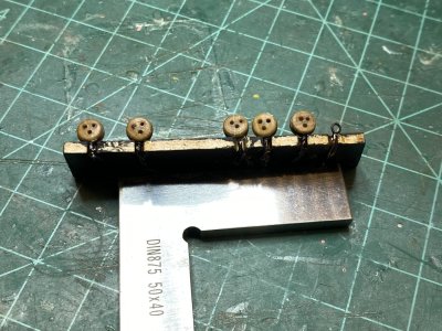

They were then wrapped by hand making sure that one of the holes of the deadeye faced the tail of the wiring.

They were then twisted tightly with a pair of needle nose pliers making sure a hole was facing the tail.

Then tail was then hammered flat.

The dead eyes were then placed in the slots of the channel and the tail bent and using pliers pressed onto the back of the channel that had a drop of CA on it. Once the CA dried another layer was applied.

Kurt Konrath
Kurt Konrath
If you have time and a small file, you might try adding the notches or teardrops to ease the curve of rope at each hole, some companies have these on the deadeyes they sell, others you have to add by hand, takes a minute per block, but makes them look better.
Thank you for the suggestion!If you have time and a small file, you might try adding the notches or teardrops to ease the curve of rope at each hole, some companies have these on the deadeyes they sell, others you have to add by hand, takes a minute per block, but makes them look better.
Rob
Kurt Konrath
Kurt Konrath
Of course you know the bottom deadeyes have "anti-gravity' tears going up the way the ropes do. Have fun, as someone showed how to improve simple kit units with this simple step before rigging.
Interesting these deadeyes do not appear to be made of wood. I tried with small files to file groves in them and they do not form groves easily. I believe they are made of some kind of very dense plastic.Of course you know the bottom deadeyes have "anti-gravity' tears going up the way the ropes do. Have fun, as someone showed how to improve simple kit units with this simple step before rigging.
Any attachments were cut or sanded away. Using the spinal needle stylets the bottom of the link was secured to the bottom hole previously drilled.
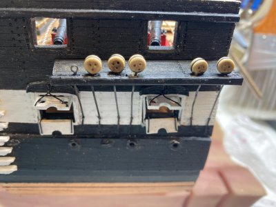
The area where the link and chainplate would connect was marked on the hull and a hole drilled. The chain plate was then attached to the link and hull and fitted to the channel. the excess chain plate was clipped away and after making sure everything fit the link and chain plate was glued into place. Small pieces of the stylet were cut out to insert into the linkage between the link and the chain plate for additional stability.
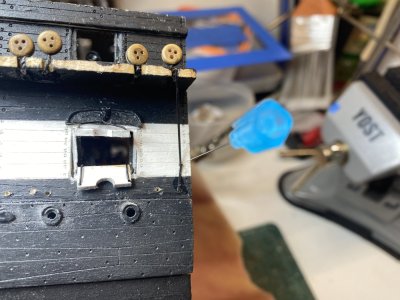
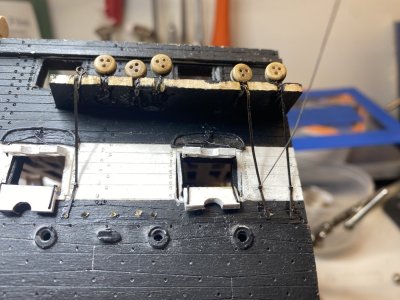
The area where the link and chainplate would connect was marked on the hull and a hole drilled. The chain plate was then attached to the link and hull and fitted to the channel. the excess chain plate was clipped away and after making sure everything fit the link and chain plate was glued into place. Small pieces of the stylet were cut out to insert into the linkage between the link and the chain plate for additional stability.


The main mast is made from a 7/16" dowel. The instructions say to cut the dowel to 16 3/8" long. My measurements off the plans make it 1/4" longer. So I split the difference and made it 16 1/2" long. Using a small plane and sandpaper, I tapered the mast from the level of the spar deck to a diameter of 3/6" at each end. It did not take long to do both. I made a small 7/32" projection to fit into the mast foot.
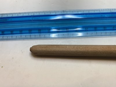
The mast slipped easily into the decks and mast foot.
The top 3 1/8" of the mast is to be made into a tapered square section. I drew 4 lines 90 degrees apart and used a plane, files and sandpaper to square off that end.
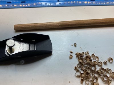
After that a 1/4" tenon was cut on the top of the mast, ruins a sharp chisel blade. It actually went a lot easier than I thought it would.
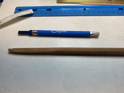

The mast slipped easily into the decks and mast foot.
The top 3 1/8" of the mast is to be made into a tapered square section. I drew 4 lines 90 degrees apart and used a plane, files and sandpaper to square off that end.

After that a 1/4" tenon was cut on the top of the mast, ruins a sharp chisel blade. It actually went a lot easier than I thought it would.

Last edited:
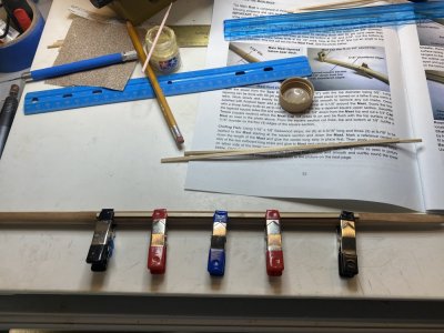
A "chafing fish" was then put onto the mast using 1/8 X 1/16" strip. 3 pieces were to be 8 7/8" long going from the top of the spar deck mast surround to the tapered square part. Measuring that I found the part to be about 1/16" too long.
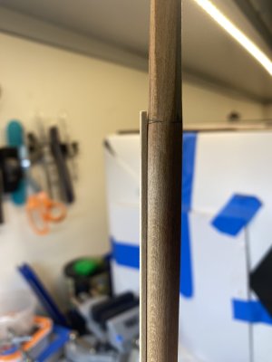
The strips were trimmed to get the length I wanted. One side on the flat side of the tapered square was called the front of the mast and a line was drawn from the middle of that square end to the foot of the mast. One of the longer pieces were then glued from the end of the tapered square down.
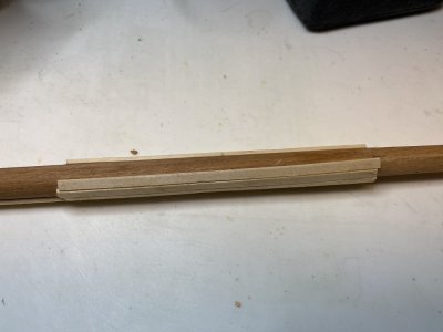
Adjacent strips were chamfered along one edge to fit closely to the other strip and glued in place.
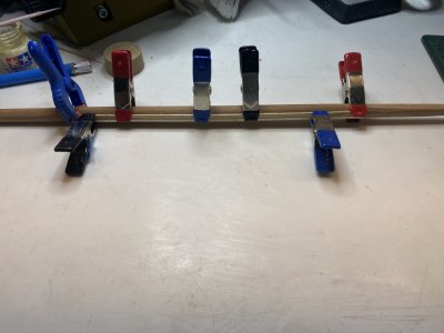

The strips were trimmed to get the length I wanted. One side on the flat side of the tapered square was called the front of the mast and a line was drawn from the middle of that square end to the foot of the mast. One of the longer pieces were then glued from the end of the tapered square down.

Adjacent strips were chamfered along one edge to fit closely to the other strip and glued in place.

Last edited:
The nine strips for the "chafing fish" (I have been unable to find this term in any nautical dictionary) were attached to the mast. You have to be aware that it only covers about 3/4 of the circumference. As far as I know this is what is wanted for this. I will use some wood filler and sand it smooth.

While I was waiting for the strips to dry on the mast I started working on the fighting platform that goes onto the mast. The two laser cut pieces were glued together making sure they registered exactly since there are many holes for eyebolts and deadeyes to work on. The frame that fits on is only 1/32" thick so handle it carefully.
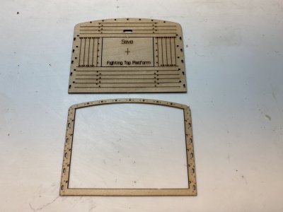
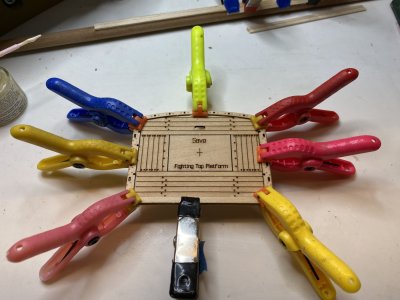
The upper crosspieces where then attached.
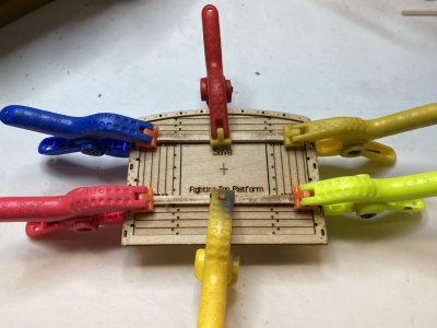


The upper crosspieces where then attached.

Last edited:
The support timbers were then placed using 1/16 X 1/16" strip. The Center mark in the center area that will be removed later made for a very convenient mark to align the support timbers.
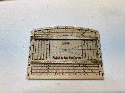
If I had thought about it a bit more I would have made the lines for the support timbers before the crosspieces went on. It would have made things a bit easier.
The timbers went on easily. Note the forward ones are notched to fit over the frame/ This was easy to accomplish using s chisel blade.
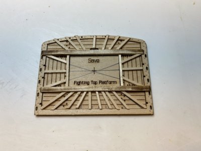

If I had thought about it a bit more I would have made the lines for the support timbers before the crosspieces went on. It would have made things a bit easier.
The timbers went on easily. Note the forward ones are notched to fit over the frame/ This was easy to accomplish using s chisel blade.

Last edited:
Kurt Konrath
Kurt Konrath
Were the fish to long, or did your compromise on mast length make it too short!A "chafing fish" was then put onto the mast using 1/8 X 1/16" strip. 3 pieces were to be 8 7/8" long going from the top of the spar deck mast surround to the tapered square part. Measuring that I found the part to be about 1/16" too long.
View attachment 527971
The strips were trimmed to get the length I wanted. One side on the flat side of the tapered square was called the front of the mast and a line was drawn from the middle of that square end to the foot of the mast. One of the long3er pieces were then glued from the end of the tapered square down.
View attachment 527972
Adjacent strips were chamfered along one edge to fit closely to the other strip and glued in place.
View attachment 527973
Kurt Konrath
Kurt Konrath
The fighting top is looking good, but I never understood why all the wood was on top, where sailors stood, versus underneath. I know there was a crosstree that it sat on, but all the edges of raw wood and mostly bare feet, seems like it would be hard to stand firm in a rough sea!
Do the plans say where the saved piece will be used later?
Do the plans say where the saved piece will be used later?


