- Joined
- Mar 1, 2022
- Messages
- 692
- Points
- 308

Beg your pardon, Allan. Due to my poor english I'm a bit confused about the meaning of "...to be be sided... etc."Thanks Allan! Most useful and appreciated. Regards, Alberto
 |
As a way to introduce our brass coins to the community, we will raffle off a free coin during the month of August. Follow link ABOVE for instructions for entering. |
 |
 |
The beloved Ships in Scale Magazine is back and charting a new course for 2026! Discover new skills, new techniques, and new inspirations in every issue. NOTE THAT OUR FIRST ISSUE WILL BE JAN/FEB 2026 |
 |

Beg your pardon, Allan. Due to my poor english I'm a bit confused about the meaning of "...to be be sided... etc."Thanks Allan! Most useful and appreciated. Regards, Alberto
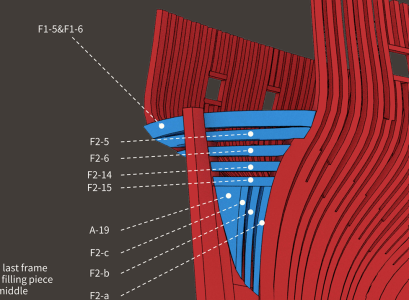
As you can see in this pic below, the wing transom is made up of 2 pieces. F1-5 and F1-6.View attachment 512455
The chocks squared to the sternpost (n. 1-10 in the picture above). Even the sole wing transom would work to me. Thanks in advance!
Kind Regards, Alberto


Looking good. Coming together really well Jeff. I shall be starting work on the stern deadwood and keel parts tomorrow, bearing in mind your comments about the misnumbering of the parts. Although a very minor issue and easily worked out, I've found this is a very common occurrence with these PoF kits. It's been no problem . . . yetSo, here is a few more pics of the ongoing build. These parts are for both the bow and the stern.
I have also glued the pieces of the keel together but no picture of that since it just looks like a stick.
You can see pieces of the keel at the top of the middle picture, if you really want to see them.
The flat portion of the keel measures about 72 cm (or a little over 28 inches if you prefer).
I'm trying to work out in my head how to make the kerfs in the bottom of the keel and make them look good.
View attachment 512290View attachment 512291View attachment 512292View attachment 512293
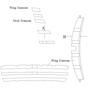
Your English is fine Alberto. If you look down on the transom you will see the moulded dimensions and if you look them from astern you will see the sided (thickness in this case) dimension. Same goes for frames. The in and out is the moulded dimension and the fore and aft is the sided dimension. This can be confusing, but if you look at the old contracts, they use these terms. The sketch below shows these, sided A and moulded B The example below is from a different ship but should make sense.Due to my poor english I'm a bit confused about the meaning of "...to be be sided... etc."

In the kit, it's not port and starboard sides. it is 2 pieces top and bottom to make one timber.This seems unusual. The wing, deck transoms and others were usually one piece, but some filler transoms were in two pieces on older vessels. Photo below shows an example from a 17th century model.
Allan
View attachment 512494

Thanks a lot, Allan. I got it! Much appreciated!Your English is fine Alberto. If you look down on the transom you will see the moulded dimensions and if you look them from astern you will see the sided (thickness in this case) dimension. Same goes for frames. The in and out is the moulded dimension and the fore and aft is the sided dimension. This can be confusing, but if you look at the old contracts, they use these terms. The sketch below shows these, sided A and moulded B The example below is from a different ship but should make sense.
Hope this helped
Allan
View attachment 512493
Thanks Jeff.In the kit, it's not port and starboard sides. it is 2 pieces top and bottom to make one timber.

So nice!A picture is worth....
View attachment 512524
Thank you.So nice!
Jeff,So, here is a few more pics of the ongoing build. These parts are for both the bow and the stern.
I have also glued the pieces of the keel together but no picture of that since it just looks like a stick.
You can see pieces of the keel at the top of the middle picture, if you really want to see them.
The flat portion of the keel measures about 72 cm (or a little over 28 inches if you prefer).
I'm trying to work out in my head how to make the kerfs in the bottom of the keel and make them look good.
View attachment 512290View attachment 512291View attachment 512292View attachment 512293
We are really 17th century Shipwright apprentices (not salaried) to Master Shipwright Allan. Deptford shipyard ?Your English is fine Alberto. If you look down on the transom you will see the moulded dimensions and if you look them from astern you will see the sided (thickness in this case) dimension. Same goes for frames. The in and out is the moulded dimension and the fore and aft is the sided dimension. This can be confusing, but if you look at the old contracts, they use these terms. The sketch below shows these, sided A and moulded B The example below is from a different ship but should make sense.
Hope this helped
Allan
View attachment 512493
Master Shipwright????? No way. Maybe in the second year of the normal seven year apprenticeship of those days.We are really 17th century Shipwright apprentices (not salaried) to Master Shipwright Allan.
Shipyard, yes, but not Deptford.Deptford shipyard ?
Hi AlexI just joined my false keel pieces with a plain scarph, rather than a nibbed scarph as shown in the instruction....easy, cannot even see the joint...

We were referring to the false keel. See my image I provided above.Hi Alex
Unlike the keel I don't think the false keel had a nibbed scarph. Could you post a pic?
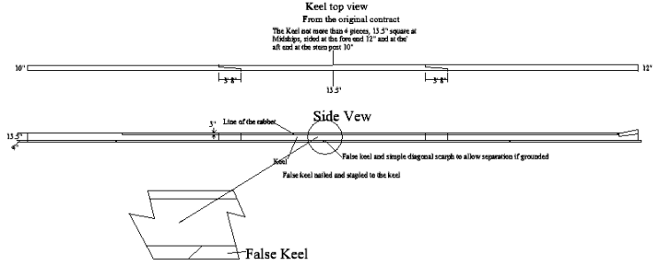
Below shows the common joinery for the keel and false keel for 18th century RN ships. Is this more like what the plans show? Note the direction of the plain scarph on the false keel to allow it to easily separate if the ship grounds.
Thanks
Allan
View attachment 512538
Hi AllanHi Alex
Unlike the keel I don't think the false keel had a nibbed scarph. Could you post a pic?
Below shows the common joinery for the keel and false keel for 18th century RN ships. Is this more like what the plans show? Note the direction of the plain scarph on the false keel to allow it to easily separate if the ship grounds.
Thanks
Allan
View attachment 512538
And would the staples be large enough to see at this scale?Hi Allan
The kit's plans show a ribbed scarp for the false keel. However, I used a plain diagonal scarph on my build, thinking that in case of grounding, it was desired for the false keel to take the brunt of the force and fall apart easily thus protecting the keel. A ribbed scarph would not come undone as easily as a plain diagonal scvarph.
A question for you: The false keel was stapled to the keel with copper staples. Do you know how many staples per length of keel ? I imagine they were placed from the side off the falls keel vertically to side of the keel. I have never seen these depicted in a model, or an illustration. Maybe I wasn't looking....
Alex R
Hi Allan
The kit's plans show a ribbed scarp for the false keel. However, I used a plain diagonal scarph on my build, thinking that in case of grounding, it was desired for the false keel to take the brunt of the force and fall apart easily thus protecting the keel. A ribbed scarph would not come undone as easily as a plain diagonal scvarph.
A question for you: The false keel was stapled to the keel with copper staples. Do you know how many staples per length of keel ? I imagine they were placed from the side off the falls keel vertically to side of the keel. I have never seen these depicted in a model, or an illustration. Maybe I wasn't looking....
Alex R
This is from The Fully Framed Model (Antscherl Vol 1, p 31): Very much like a modern-day staple in shape ( [ ), these were driven flush into the sides of the keel and false keel. Steel states that they were placed "about three feet apart." These staples had a flat cross section, about 1 1/2" wide and 8" long.And would the staples be large enough to see at this scale?
