So, about .7 mm x 4 mm in 1/48.This is from The Fully Framed Model (Antscherl Vol 1, p 31): Very much like a modern-day staple in shape ( [ ), these were driven flush into the sides of the keel and false keel. Steel states that they were placed "about three feet apart." These staples had a flat cross section, about 1 1/2" wide and 8" long.
They were made of copper.
-

Win a Free Custom Engraved Brass Coin!!!
As a way to introduce our brass coins to the community, we will raffle off a free coin during the month of August. Follow link ABOVE for instructions for entering.
-

PRE-ORDER SHIPS IN SCALE TODAY!
The beloved Ships in Scale Magazine is back and charting a new course for 2026!
Discover new skills, new techniques, and new inspirations in every issue.
NOTE THAT OUR FIRST ISSUE WILL BE JAN/FEB 2026
- Home
- Forums
- Ships of Scale Group Builds and Projects
- Modelship Dockyard PoF HMS Enterprize 1774 - 1/48
You are using an out of date browser. It may not display this or other websites correctly.
You should upgrade or use an alternative browser.
You should upgrade or use an alternative browser.
Paul,
Thank you... That would be a LOT of staples..mmmH. Maybe Flatten out 0.7mm copper wire, cut it into 4 mm lengths and glue each one...or not show them at all....
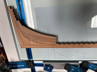
Today, continued work on the keel.
All I have to do to finish the keel is to put on the bow horseshoe and the stern iron pieces.
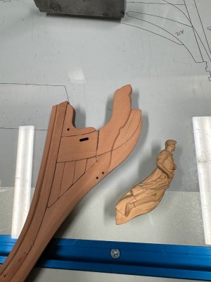
I carved out and thinned the knee of the head and dry-fitted the figurehead.
I'll start building the jig in the next day or two.

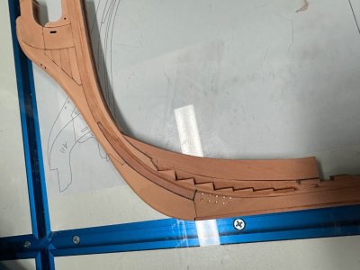
Alex R
Thank you... That would be a LOT of staples..mmmH. Maybe Flatten out 0.7mm copper wire, cut it into 4 mm lengths and glue each one...or not show them at all....
Today, continued work on the keel.
All I have to do to finish the keel is to put on the bow horseshoe and the stern iron pieces.
I carved out and thinned the knee of the head and dry-fitted the figurehead.
I'll start building the jig in the next day or two.


Alex R
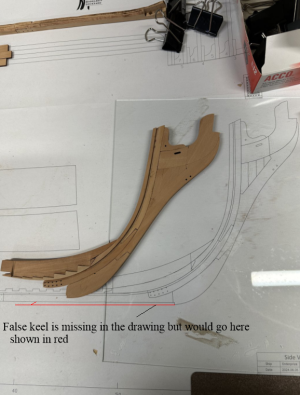
Hi Jeff, I think maybe we are talking about two different thingsWe were referring to the false keel. See my image I provided above.
Not a big thing, but wondered why the false keel pieces would have a complex scarph when it was not necessary or actually done.The kit's plans show a ribbed scarp for the false keel.
Alex's photo shows the false keel inplace as in the below pictures
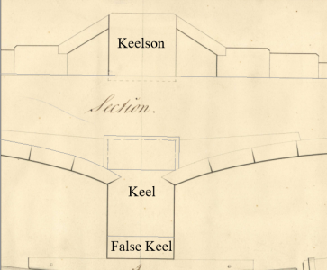
I added the names of the parts on the below drawing from circa 1799, Staples at this scale would be interesting to see. Has anyone seen these on any contemporary models?
Last edited:
- Joined
- Mar 1, 2022
- Messages
- 692
- Points
- 308

This scarph and its layout was intended to reduce the risk of false keel tearing off badly in case the ship run aground. I can't provide you with the source of my statement, but I swear I read it somewhere here on SOS. @AllanPK, the true living encyplopedia in this forum, may possibly confirm that. Cheers!Hi Jeff, I think maybe we are talking about two different things
Not a big thing, but wondered why the false keel pieces would have a complex scarph when it was not necessary or actually done.
Alex's photo shows the false keel inplace as in the below pictures
View attachment 512570
I added the names of the parts on the below drawing from circa 1799, Staples at this scale would be interesting to see. Has anyone seen these on any contemporary models?
View attachment 512572
- Joined
- Oct 17, 2020
- Messages
- 1,691
- Points
- 488

Hi Allan, for your information , the biscuits under the madiers are to be made to convey water into the bilge well .FrankHi Jeff, I think maybe we are talking about two different things
Not a big thing, but wondered why the false keel pieces would have a complex scarph when it was not necessary or actually done.
Alex's photo shows the false keel inplace as in the below pictures
View attachment 512570
I added the names of the parts on the below drawing from circa 1799, Staples at this scale would be interesting to see. Has anyone seen these on any contemporary models?
View attachment 512572
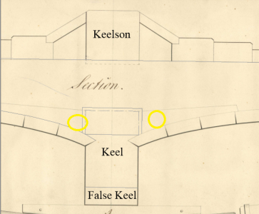
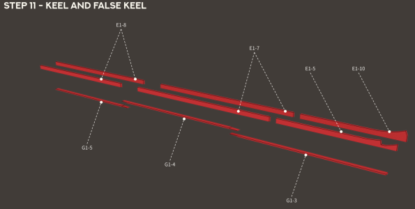
In this drawing I've attached, wouldn't parts G1-3 through G1-5 be considered the false keel?Hi Jeff, I think maybe we are talking about two different things
Not a big thing, but wondered why the false keel pieces would have a complex scarph when it was not necessary or actually done.
Alex's photo shows the false keel inplace as in the below pictures
View attachment 512570
I added the names of the parts on the below drawing from circa 1799, Staples at this scale would be interesting to see. Has anyone seen these on any contemporary models?
View attachment 512572
That was the detail I included in my post #37. And that is what I had questions about.
This scarph and its layout was intended to reduce the risk of false keel tearing off badly in case the ship run aground.
In this drawing I've attached, wouldn't parts G1-3 through G1-5 be considered the false keel?
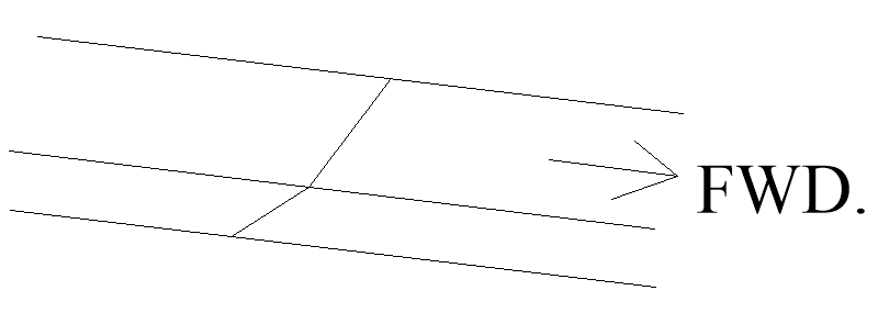
Yes they are sacrificial pieces to tear away if hitting the bottom. The scarph is designed so if grounding, the piece that hits will tear off without tearing away the pieces abaft. The scarphs were not like G1-3 to G1-4 or G1-4 to G1-5 in the drawing above, but rather, simple angled scarphs.
Allan
After running some tests I chose to not install them. Everything I tried looked out of scale and unrefined.Paul,
Thank you... That would be a LOT of staples..mmmH. Maybe Flatten out 0.7mm copper wire, cut it into 4 mm lengths and glue each one...or not show them at all....
Thank you! That is exactly what I wanted.Yes they are sacrificial pieces to tear away if hitting the bottom. The scarph is designed so if grounding, the piece that hits will tear off without tearing away the pieces abaft. The scarphs were not like G1-3 to G1-4 or G1-4 to G1-5 in the drawing above, but rather, simple angled scarphs.
Allan
View attachment 512582
I never thought about the angle. I would not be surprised if it varied from shipyard to shipyard though. At our scales, I doubt anyone will notice  I did look in a few books but found no contemporary details on this. An interesting point is that there were usually two false keels to protect the keel and reduce leeway on English ships built after about 1800 (Peter Goodwin, The Construction and Fitting of the English Man of War page 8)
Allan
Allan
- Joined
- Sep 10, 2024
- Messages
- 1,022
- Points
- 393

Thank you! That is exactly what I wanted.Is the angle in that drawing accurate? It looks like about 45 deg.
From WoodenBoat.com:
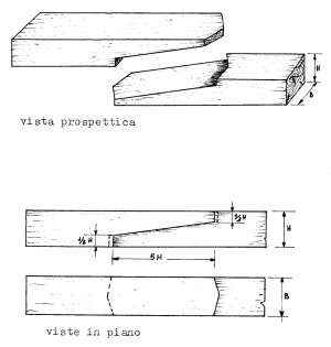
Scarfs are defined by the length of their slopes in relation to the thickness of the pieces being joined together; this relationship is described as a simple ratio—for example, a 4:1 scarf in a 1"-thick piece would have a slope length of 4", measured parallel to the timber’s surface. Traditionally, scarf ratios have been driven by the location of the scarf: 4:1 for planks, 6:1 (possibly 8:1) for keels, and 12:1 for spars. The old Lloyd’s of London rules state that plank scarfs should not have a length-to-thickness ratio less than 4:1, adjacent planks should not have scarfs within 1.2m of each other (about 4'), and a minimum of three complete planks should separate scarfs in the same transverse plane. In addition, keel scarfs should have a ratio no less than 6:1, and the keel and hog scarfs should be spaced by at least 1.5m (about 5'), while being clear of engine bedlogs and maststeps. In those historical instances, it can be deduced that an increased scarf ratio leads to greater strength but that scarfs still represent weak spots that should be spaced out and not subjected to high localized loads. Richard Birmingham, in his book Boat Building Techniques, states that the efficiency of scarfs ranges from 65 percent of the strength of solid timber for a 4:1 ratio and up to 95 percent for a 20:1 ratio. The source of these values is not clear, nor is their accuracy when utilizing various glues and wood species.
Good stuff, Russ! The thought that occurs to me, however, is that the scarf on the false keel is not structural; the thing is a tear-away...
The modeled false keel timber is quite thin so I made the joint about 45 degrees (visually) on the Kingfisher. I also made it out an a different species of wood to add a visual talking point.
I'll crawl back under my rock now and leave you Enterprise folks to your work...for the life of me I can't imagine why you guys should care what I think .
.
The modeled false keel timber is quite thin so I made the joint about 45 degrees (visually) on the Kingfisher. I also made it out an a different species of wood to add a visual talking point.
I'll crawl back under my rock now and leave you Enterprise folks to your work...for the life of me I can't imagine why you guys should care what I think
 .
.- Joined
- Oct 17, 2020
- Messages
- 1,691
- Points
- 488

Hi Allan, for your information , the false keel does not provide for palletizing.Frank
- Joined
- Sep 10, 2024
- Messages
- 1,022
- Points
- 393

I can't imagine why you guys should care what I think
Because you're the Doc! That's why!
- Joined
- Oct 17, 2020
- Messages
- 1,691
- Points
- 488

Hi Allan, they are image found in the Web.FrankGrazie Francesco, but I am not sure what you mean by palletizing. I realize it is a translation thing.
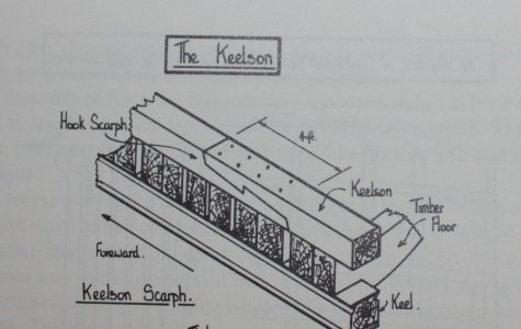
Where is your attached drawing from? It looks a similar to a scarf on the keelson.
Thanks again
Allan
From Goodwin page 28
View attachment 512596
Hi Allen. The Bluenose had it, but they called it a shoe. Made it also under my BN:Has anyone seen these on any contemporary models?

Attaching on the keel with treenails was ‘Artistic License’ and ‘Free Interpretation’ (AL-FI). Easy to replace a part when damaged.
As Paul quoted:
Love the very interesting build-logs of this Enterprizes!I'll crawl back under my rock now and leave you Enterprise folks to your work...
Regards, Peter
Last edited:
Thanks Peter, but I guess I was not very clear.The Bluenose had it, but they called it a shoe. Made it under mine:
Allan
It was my interpretation of ‘contemporary’+’model’.Thanks Peter, but I guess I was not very clear.I was referring to staples being shown on warship models made in England in the 18th century that had a false keel held under the keel. Sorry for the confusion, my fault.
Allan
Regards, Peter
Last edited:


